B22 + GRLV PSU + toroidy transformer 100VA + Fofelix line filter

2 B22 fully populated populated boards
1 fully populated Golden reference power supply configured for 28V (the picture still missing some parts but all will be assembled before shipping.
1 toroidal transformer audio grade from toroidy.
240V-25V 100VA dual secondaries.
1 line filter with Comovo choke from coilcraft.

Selling this as a kit for a 2 channel headphone amp, to fund other projects.

Price is 250€ with shipping in Europe and PayPal taxes included.

IMG_7811.jpegIMG_7810.jpegIMG_7813.jpegIMG_7809.jpeg

Force cancelling subwoofer with Dayton Audio EPIQUE E180HE-44 & T.Rack DSP 4x4 Mini AMP

I would like to share my experimentation and realization of an active SUB based on the force cancelling principals, also called dual opposing driver configuration, based on an “exotic” setup:

The Sub:

For the sub I used 2 speakers from Dayton Audio : EPIQUE E180HE-44 200W – 2 x 4 Ohm 84dB 25Hz. They have a dual coil, and an impressive Xmax of 14 mm for such small speakers. In a sealed box, the volume for the 2 speakers is only 16 Liters, so quite small, for a big sound !
The box finalized:

1714481039764.png


The AMP:

To drive the speakers, I used a very interesting and rather cheap Amp with integrated DSP: the T.Rack DSP 4x4 Mini AMP, not used in a usual way I would say.

I used in particular the DSP filters section in order to:
  • Cut high frequencies >100 Hz
  • Cut Low frequencies < 25 Hz
  • Compensate the loss of efficiency of the sub bellow 60 Hz in a closed box, by a regular increase of the gain.
1714481067485.png


For the power amp section, I also selected the T.Rack Mini Amp because it has 4 outputs of 60 Watts each, which matches the 4 coils of the 2 sub speakers !

Some will argue that it would be simpler to use a DSP and an amp of 200 W. Indeed , but for the price of the T Rack, I didn’t find such good combination.


The overall picture of the full system:

1714481090246.png

FS. Soekris dac1101 R-2R USB DAC

For sale Soekris dac1101 R-2R USB DAC
Asking price: 275EUR + shipping
Shipping: original box, preferring shipping to EU countries

Some measurements I've done on the unit can be found here

Reason for sale is that I have a Soekris dam1021 based DAC build as well and some other DAC-s, so just have too many toys.

Attachments

  • dac1101_front.jpg
    dac1101_front.jpg
    154.2 KB · Views: 407
  • dac1101_back.jpg
    dac1101_back.jpg
    98.4 KB · Views: 388

Update for Elektor Crescendo Power Amplifier 1982

I have lived with this 180 W amplifier for almost two decades. It has been proven to be good sounding and reliable over the years, even though I must admit a little tricky sometimes. In the posts in the www.diyaudio.com I am glad too see that the Crescendo has good reputation, and many have built it and likes it a lot. The Crescendo is still very competitive I think, and should be a contender to the Hall of Fame of diy-amplifiers, if there is one!

My guess is that almost everyone who built this amplifier has or had some problem with high frequency oscillations and perhaps some hum induced from the power supply. High frequency oscillations can be hard to get rid of. There have been some tweaks published in the Elektor I have tried, beside some that I have collected from postings on the Internet.

My amplifier had a lot of high frequency oscillations, and the RC-chain on the output went up in smoke. But the solution was easy; a small capacitor across the bias resistor solved it! I think it should been there in the first place. It is common practice in many costructions.

So, here is a listing of proven solutions to kill or reduce HF oscillations:
  • 47nF in parallel with the bias resistor P1. This killed all mine HF osc.
  • Using non-inductive source resistors R27-R30 is recommended by Elektor and have worked for others.
  • Put 1 nF between n-channel source resistors R27 and R28 is also recommended by Elektor.
  • Move the RC-chain R32 C16 from PCB to the speaker chassi posts can kill some HF osc. This is a solution used in various builds for this reason.
Suggestions for improvements of stability and performance:
  • Replace cascade transistors T8 and T10 BF469/470 with MJE350/340. This may improve sound quality. Or not.
  • Active DC regulation for lower DC offset. Could also improve sound quality.
  • Resistive collector load for the voltage amplifier (it sees a varying impedance in the gate of the mos fet's) may improve over all stability. This is used in many constructions.
  • Different feedback paths for LF and HF signal could improve stability. This is used in other constructions.

I still have some problems with hum, and I have rewired a lot a tried many other things. Nothing helps. Stabilizing the input section didn't. To compact housing perhaps? Left and right channel does not hum equally either, and it is very irritating!

On the other hand, one of the channels have a defective mos fet, but still works...

Anyway, I think this amplifier deserves another decade using some of the tweaks. I was a bit disappointed with the new Crescendo ME, I can't use it to upgrade the original Crescendo, and there are problems with high frequency oscillations in that one too!

I will be happy to receive comments and help to update the reference columns with links to diyAudio forums.

Can I still press down the frequency bump between 2.5k - 4.5k ?

Hi experts, I purchased Homepod horn tweeter from ebay and trying to play with it.
The original output frequency tested in yellow waveline highest.

I tried used 1st order crossover 4.7uf cap (green) 3.3uf (pink) and 2.2uf, (lowest yellow line)

I also tried 2nd and 3rd order crossover, the wave doesnt have much difference or improvement compare to 1st order.

So I guess I am settled with 1st order crossover method.

My question is there a way to press down the bump +5db in between 2.5k-4.5k frequency.

Is there any method to add components? Series or parallel (Caps, resistor or inductor) to make the bump more flat?

All constructive advice are welcome.

Thank you.

Attachments

  • IMG_4695.jpeg
    IMG_4695.jpeg
    756.5 KB · Views: 91
  • IMG_4671.jpeg
    IMG_4671.jpeg
    359 KB · Views: 84

For Sale Finished DIYINHK double 3.3V/5V/7V PSU, 4x LT3045, 0.56 μV noise

Finished double PSU by DIYINHK, with four LT3045 regulators and ultra-low noise of only 0.56 μV. The LT3045 is one of the best regulators that can be had today.

New unfinished $60, bought from DIYINHK on January 11, 2021. Asking price €45 excluding shipping from The Netherlands.

The PSUs are configured for 5V output. 3.3V or 7V is easily selectable per PSU using jumpers.

Maximum current per PSU is 1A or they can be paralleled for 2A. Nominal current is 0.5A.
There's room on the PCB for two extra LT3045 when a higher current is required.

Both PSUs are equipped with an original Murata EMI filter.

Capacitors are Panasonic EEUFC 5600μF and WIMA MKS.

As good as new.

tempImageB0Cypn.gif


tempImageWQo0zE.gif

All open baffle

Anyone heard these Italian crazy looking all open baffle speakers? How can they produce enough low bass?

Attachments

  • 77589-dccaa17f5ab79c4e47c5d152d82fc8a4.jpg
    77589-dccaa17f5ab79c4e47c5d152d82fc8a4.jpg
    95.4 KB · Views: 786
  • 77583-4b370a316e738ea14a47a54d85258eb1.jpg
    77583-4b370a316e738ea14a47a54d85258eb1.jpg
    57.5 KB · Views: 744
  • 77581-d1b6f5ab0bad960f34d8a8bddf1c96f6.jpg
    77581-d1b6f5ab0bad960f34d8a8bddf1c96f6.jpg
    125.4 KB · Views: 767
  • IO-naked-hifi-news-munich-may-2023-feat-1024x576.jpg
    IO-naked-hifi-news-munich-may-2023-feat-1024x576.jpg
    59.9 KB · Views: 815
  • IO-naked-hifi-news-munich-may-2023-3.jpg
    IO-naked-hifi-news-munich-may-2023-3.jpg
    47.4 KB · Views: 905
  • 77584-268d2cece186274946b3f55f104b0d9f.jpg
    77584-268d2cece186274946b3f55f104b0d9f.jpg
    39.4 KB · Views: 661
  • 77585-8c3c83ad5bd04c33b27988144f3a04b5.jpg
    77585-8c3c83ad5bd04c33b27988144f3a04b5.jpg
    41.9 KB · Views: 732

Bias servos

A couple of us usual crackpots have been in discussion on the I&A forum trying to guide (yeah, right) a newbie-ish who was thinking about building a “big” amplifier for bass guitar using sweep tubes. Something about the size of my big 6550 monoblocks. In principle its quite possible, and pretty sure I could make it work as a demo. I’ve built a 135 watter around a quad of 26DQ5’s and it works perfectly. The only trouble I had with it was a vintage tube in the phase splitter with h-k leakage. Once corrected I had zero trouble. BUT some of us have bigger plans on the horizon. Bigger tubes, more of them, and therefore more opportunities for problems. The biggest of which is probably keeping the bias balanced. I don’t want to have to rely on precarious adjustment over time. These big sweeps aren’t necessarily matched, and probably drift over time.

I was thinking of an auto bias which would allow the cathode currents to increase under drive (unlike many approaches), but keep them in balance during the bias-up procedure and while in operation. The tubes would be individually fixed biased (since I know this works with random sweeps), and work in pairs. The idea would be to be able to have multiple pairs running simultaneously, however. Each with their own bias control. Id have to figure out the gain structure, and where the dominant pole needs to be (pretty low). I had something simplified auto-biasing a pair of un-matched type TIP transistors on the bench years ago, with large emitter resistors which somewhat limited the open loop gain, but it worked. Deliberately upsetting one side by injecting base current resulted in an increase in the other to match, until it ran out of headroom. And the error voltage would follow. I’m sort of out of actually building anything for the moment due to recent injury, and just looking back at this because I planned to use something like this on The Big One, and The Big One has come up yet again. Might not go anywhere - but I figured this needs its own thread if I want to explore it. Ive got several pairs (dozens) of “disposable” 20 watt class sweep tubes to play with, when I finally get to put this to hardware.

Attachments

  • 80E0F5A3-FF8D-407C-8236-383DCCC40DBE.jpeg
    80E0F5A3-FF8D-407C-8236-383DCCC40DBE.jpeg
    62 KB · Views: 346

ICEpower 50ASX2 Problem

I have an audio amplifier (which doesn't work) and I'd like to get it working because it's good stuff (Fender Rumble 150 Bass Amplifier Head) 😛

It just doesn't turn on. From what I can see the power supply (ICEpower 50ASX2) doesn't have any active output... but it's something more complex than the ones I've been trying to repair and learn, this one has more components :🙂

If anyone can give me some help, its possible to obtain the full schematic for this power supply? I found some information available but its only:

Amp Schematic
Power Supply Manual
Power Supply Datasheet


I've been doing some measurements and unfortunately the fuses (which are about 3) are all fine, the 2 giant capacitors (primary side) have a voltage of ~150V each

On the secondary side, I don't have any voltage, even on the Enable Pin that should be +5V (according to the manual) has 0V.

There is one component that is an NTC 5.0 and has a resistance of ~5R, which makes me believe that it's fine too.

All the elect. capacitors from the board, i measured them (with the multimeter in the capacitor mode) and the values, even being in the circuit (I didn't remove them), seems to be ok, and they seem to be of good brand and quality..

The IC SG3525 wont starts, it only has ~1.3v at Vcc pin, From what I see pin 15 is connected to a circuit that has a PNP Transistor (BCP53), and this PNP has Base and Emitter with ~15v input. But Collector Output is only ~1.3V:


http://youtu.be/VXpCVsWPq4M

Any idea?

Lanzar Optidrive 2150

I am repairing this amp and having issues on power supply.
Fets are removed a few resisters were replaved along with 4n25 and lm358.
All 4401 and 4403 drivers were replaced.
i have no drive for pin 14 on sg3525.

voltages on 3525
1: 0.920
2: 1.022
3: 0.015
4: 0.209
5: 2.086
6: 3.780
7: 2.12
8: 4.82
9: 4.89
10: 0.062
11: 2.593
12: 0.006
13: 3.615
14: 0.042
15: 13.46
16: 5.10

The scope signal on pin 11 is attached.

Attachments

  • 20240513_125549.jpg
    20240513_125549.jpg
    397.3 KB · Views: 72
  • 20240513_125549.jpg
    20240513_125549.jpg
    397.3 KB · Views: 61

Varistor Identification Help

Hi All,

Looking to confirm the specs/code on a leaded disc varistor. I’ve been able to figure the following:

S = leaded
10 = size (10mm)
K = Tolerance +/- 10%
275 = Max VAC (275v)

Not sure what the last line of digits represent, best I can tell it’s a date code?

This what I need to replace:
IMG_5329.jpeg


Here is the replacement I ordered:
IMG_5327.jpeg


Are they the same rating? Can’t find any reference to the last line anywhere or on the TDK spec sheets. (Again, assuming it’s a date/batch code..?)

Appreciate any help!!

Thanks,

Linkwitz transform on RS225?

I run RS225 in approx 25 litres. I did port them for added LF extension but I do prefer sealed. I was thinking about going back to sealed and adding a second RS225. Will halve the excursion.

But then got to thinking about doing an LT on them. RS225 in 25litres Sims as FC = 69hz and q = 0.68 for 1 woofer and 0.86 for X2 RS225. Haven't measured but I think it was about there.

I plugged this in an LT spreadsheet. The target Q=1 helps with the F6/F10. I think I would aim for a Q of 0.6 or so normally sealed. Or atleast I like the sound of that. Does this add much GD?
Have kept it quite modest for now as don't want the gain to be too high. Probably will run them on a JLE 3255 but maybe needs more power. Small ish UK living room so SPL required isn't massive.

The LT obviously asks a lot of the power demands and excursion capabilities. If I add a given LT to one woofer, what happens if I add a second woofer? The original Fsc raises. Does the 2nd driver help in the excursion? Does it make the power demands worse?

Thanks

Attachments

  • Screenshot_2024-05-17-07-40-34-06_87869c5c71fa0655e350912352595c23.jpg
    Screenshot_2024-05-17-07-40-34-06_87869c5c71fa0655e350912352595c23.jpg
    253.8 KB · Views: 131

QUAD 405 V2 Clones - Suggestions or Experience?

I am starting to setup my QUAD 405 V2 clones (pictured). Does anyone have the pictured boards and can offer advice or suggestions?


From my searches and reading I gather that there are a couple of main modifications to consider:

  • Replacing the TL071 with the OPA134
  • Replacing the green 2W 560 Ohm resistors with larger resistors and spacing them away from the PCB.

In addition to the above I was thinking of a couple other possible modifications:

  • I see pictures online of 2SC2922 based clones so I am considering using some of my genuine 2SC6145. (The closest I have.) Any warnings/suggestions? I am using +/- 40V supplies and 4 Ohm speakers.
  • The TL071 operational amplifier is powered from 3.3k Ohm resistors and 15V Zener diodes which are bypassed by 0.1uF film capacitors. I am thinking of adding 10uF Panasonic electrolytics or 10uF Monolithic ceramic capacitors under the 0.1uF. Does anyone have any suggestions? My 40V supplies might be a bit high to try replacing the 3.3k Ohm and Zener diodes with LM7815/LM7915 with their 35V absolute maximum rating. Perhaps with 3.3k Ohm and the 10uF the PSRR of the operational amplifier is more than sufficient?


Later I might give my capacitance multiplier another try and use it with this amplifier after replacing the TIP142/147 again.

Attachments

  • QUAD 405 v2 Front.jpg
    QUAD 405 v2 Front.jpg
    1 MB · Views: 1,436
  • QUAD 405 v2 Back.jpg
    QUAD 405 v2 Back.jpg
    1 MB · Views: 988

QUAD 405 clone

Hi, I recently bought a 405 amp with 34 pre-amp. One channel of the amp was faulty (both fuses blow at turn on). With the 405 came two Ebay clone boards. They are similar to the ones I've seen on Ebay except that they have a heatsink fitted and the output transistors are of the can type. Anyway... I decided to keep the 405 as quad intended and sent the amp module off for repair, meanwhile whilst I'm waiting the clone boards kept crying out to be tried.. so one +/-50v supply later (and with only one amp connected, just to be on the safe side) I turn on. All seemd fine until I connected an input. Then much distortion and hum and then came the smoke (not a lot and I can't see the damage). I have since tried the other channel and all is well. The first channel however remains loud and distorted but not smoking. I'm certain that all wiring etc was ok, the only two things I can think that I might have done wrong are; 1, overloading the input on the first attempt and 2, not running a separate 0v to the heatsink. Any ideas what I've done to my project??

Suggestions on improving acoustics in my audio cave (with pictures!)

Hi - I am in a rental house, but expect to be here for at least a few more years. As in, I don't want to spend huge money or things that will require a lot of holes in the wall (though some are fine...I can patch and paint).

I am about to ditch the 14 year old (really!) Sharp 70" TV for a 85" Sony which will be mounted, and the gear will be taken off the floor for its dignity and easier use.

Room is 18 feet long, 14 feet wide, 8 foot ceilings. Semi-submerged room, so about 50% of the walls are concrete, as is the floor. Fairly thick carpeting, and standard sheet rock ceiling (the images make it look bad, it is just standard but thick stucco-like texture)

When I moved in, obviously an empty room...and it sounded TERRIBLE. I spent a few hundred dollars and hung curtains (as you can see) which was TRANSFORMATIONAL and made the room sound pretty dang good. If I clap in the room, very well dampened...is has the acoustics of a movie theater more or less.

I feel I have mostly tamed the excessive highs. Bass is good (there is a big REL hiding in the corner, and it will shake the entire house).

Where I seem to have a little issue is some mid-bass resonance...think a few hundred hertz. I also would have no issue continuing to tame the highs a bit more.

Maybe I am leading the witness, but I keep thinking the ceiling could do with some acoustic paneling.
--Can't do anything to the floor, but it has thick carpeting, so that helps
--I do have a queen size comforter hung behind the curtain on the right-side wall (the biggest piece), and could certainly do more of that in the rear. The left side wall has a window, so I can do some but not all
--Not much I can do with the front wall, but it is fairly 'busy' with stuff so hopefully that helps
--If that back corner is a concern (where the black safe is), I could certainly put something there.

Suggestions for the ceiling...if anything at all? I would have no issue installing some lightweight panels (drilling, not gluing).

Thoughts, suggestions? Thanks!!!


Two Different Full Range Driver Wiring Help

Based on my search, I understand there may be some combing issues with using two full range drivers in the same design. I'm currently in the experiment and learn phase of speaker design. My current project is to make a small tower speaker with one front facing full range driver (the Dayton audio ps95) and one upward facing full range (Dayton audio ce65w) into an omnidirectional cone.

The drivers are both 8 ohm and I have an amp that will power down to 4 ohm. I was thinking it would be as simple as wiring the drivers in parallel, however, now I'm worried about power mismatching. My next thought was to use a double binding post and wire each driver to is own post, but I can't find any research on that.

I'm asking for wiring guidance and thoughts about my current project.

Thank you.

Schematic wanted for passive Crossover Unit of PMC's MB2/MB2s

Some attachments under
https://www.diyaudio.com/community/threads/diy-pmc-mb2-clone.310018/
and
https://www.diyaudio.com/community/threads/pmc-mb2s-clone.218042/
are unfortunately externally hosted and not upload here - thus no longer available.
Probably also the circuit diagrams of the associated crossover networks.

Maybe one of the member can upload this - thank you very much.

P.S.: according the attached images and those under
http://szymonfaber.pl/?p=1351
the parts for the crossover network unit mainly low-cost bi-polar elcaps and no air-coil inductors

Attachments

  • 15-1024x768.jpg
    15-1024x768.jpg
    184.4 KB · Views: 105
  • 16.jpg
    16.jpg
    151.3 KB · Views: 90
  • bb5(2).jpg
    bb5(2).jpg
    38.3 KB · Views: 77
  • images.jpg
    images.jpg
    9.4 KB · Views: 72
  • maxresdefault.jpg
    maxresdefault.jpg
    71.6 KB · Views: 74
  • IMG_0010.thumb.JPG.9b9efdec5bd1ec19b1ea533b22997c9a.jpg
    IMG_0010.thumb.JPG.9b9efdec5bd1ec19b1ea533b22997c9a.jpg
    194.1 KB · Views: 81

DIY-Danny & The Bad Cabs : Have Mic Will Trouble :)

Some interesting measurements on Cab vibrations further down his vid :

Login to view embedded media
Danny sellz tonz of Hi-Rez foam (not cheap!) , probably there are now more speakers upgraded with his stuff than unstuffed ones 🙂

Yes a Bad Cab can ruin your speaker completely no matter how expensive drivers your are using!

We need more research on how to build a trouble-free cabinet well worth the money!

Thick wallz will fix any cab problemz?

Well be prepared for 2inch thick chipboard TANX 🙂

Login to view embedded media

No brand polypropylene caps

hello,

I want to replace some old aluminium caps in several altec models cabinets (mainly axial 8.2uF) with polypropylene.

I contacted some electronic parts resellers and mainly I found no brand caps. Then I contacted "hifi" resellers, I was told to choose between no brand or golden price caps !

So I'm not even sure I actually have polypropylene capacitors and obviously no information about their structure 🙁

I think I'm going down on dubillier capacitors... Any advices or tips ?

For Sale Balanced Wayne’s Preamp with headphone outputs

I built this as an experiment and I loved it so much I’m building myself a dual mono version in a larger chassis.

  • 3 balanced inputs and one balanced output
  • Pin 1 is attached to audio ground so you can use xlr adapters for single ended inputs and outputs (attaching pin 1 to the chassis adds hum to the single ended inputs and headphone jack)
  • RK27 Alps 4 gang pot
  • Grayhill Selector switch
  • balanced headphone output
  • Single ended headphone output
  • VRDN PSU set up for wall wart
  • AC-AC Triad Wall Wart

Attachments

  • IMG_0970.jpeg
    IMG_0970.jpeg
    507.5 KB · Views: 177
  • IMG_0972.jpeg
    IMG_0972.jpeg
    466.8 KB · Views: 185
  • IMG_0995.jpeg
    IMG_0995.jpeg
    426.7 KB · Views: 184

Adcom GFA-5300 repair and restoration: DC offset issue

Hi Everyone,

A few weeks ago I rescued a broken, neglected, and abused GFA-5300. I now have the amp working, but can't get the DC offset adjusted to spec, and am hoping for some help on next steps.

To get the amp to this point I did the following:
  • remounted a dislodged transformer (the amp had been dropped)
  • removed years of dust and crap
  • changed caps (factory Lelons were bloated and leaking, with some hanging on by a single leg)
  • scrubbed and reflowed boards (the drop caused some severely cracked joints)
  • gently tightened transistor mounts
  • new thermal grease on the thermostat and bias transistor

Plus some bonus stuff:
  • changed trim pots to Bournes
  • changed input cap to Panasonic polypropylene
  • changed signal path resistors to metal film
  • cleaned up wiring
  • added IEC + earth loop breaker from Hoppes Brain

With those tasks complete, the following good things happen:
  • amp powers on
  • PS voltages are correct
  • bias adjusts correctly
  • plays music!

Unfortunately I can't get the DC offset adjusted correctly. I'm measuring with the amp warmed up, no load, and the inputs shorted. Instead of no more than +/-10mv (per the service manual), I'm getting 60mv on the right channel and 110mv on the left with the trim pots fully adjusted (DC values go higher if I turn the trim pots the other direction).

From what I've read in other threads, the IRFD210 LTP transistors could be suspect, in which case I'd have to source matched pairs. Is there something else I can try?

Thanks in advance

Attachments

My "semi" OB Project

Hello, this is my first OB project.
For the moment I have preferred to use a sealed box for the low frequency driver.
I don't have a dedicated room for the HiFi system, so I can't separate the boxes from the back wall as much as would be advisable, even so, I wanted to try something different from what I had previously built, and an open baffle caught my attention. .
The system is the following:
Beyma TPL150 for high frequencies from 1300Hz.
FaitalPro 10PR320 as a medium frequency driver from 180 to 1300Hz.
B&C 15PS100 from 32 to 180Hz.

The active system is filtered and equalized with a Minidsp 4x10.
I'm still in an adjustment period, but I like it...😆

I have carried out the entire carpentry and painting process in my garage, it has been a process of many months, but it has been worth it from my point of view.
I hope you like it.
Greetings.

Attachments

  • _DSC1825 1.jpg
    _DSC1825 1.jpg
    359.4 KB · Views: 223
  • _DSC1816.jpg
    _DSC1816.jpg
    369.7 KB · Views: 216
  • _DSC1824.jpg
    _DSC1824.jpg
    297.2 KB · Views: 212
  • _DSC1823.jpg
    _DSC1823.jpg
    316.3 KB · Views: 204
  • _DSC1830.jpg
    _DSC1830.jpg
    288 KB · Views: 213

Problems associated with a capacitive load

The speaker crowd have been discussing the merits of avoiding a load like this, and wondering why so many have done this blindly and apparently not had a problem.

What problems may happen and how would the uninitiated tell? What impedance threshold/frequency range should be considered risky? Are some amplifier types more susceptible?

h2.png

Purifi, Various drivers and parts, Linaeum, Sony Electrostatic - UK

Various parts and spares for sale

  • Purifi PTT6.5 bass driver (x1)
  • Purifi PTT6.5PR-NF1-01 (x1)
  • Purifi crossover
  • Single speaker (for above)
  • Various full range, mid, bass, drivers from 1" to 6"
  • NXT, BMR drivers
  • Various tweeters
  • Seas 27TBCD/GB-DXT H1499-06 tweeter (PMC, ATC, Harbeth etc)
  • Optimus/Genexxa (Linaeum) dipole ribbon tweeters/speakers x6
  • Pair of Sony SA-S1 electrostatic tweeters with PSU driver boards
  • Aktimate (Creek/Epos) Mini (x4) Micro (x2) active speakers working for spares repair
  • Various amp boards, crossovers
  • BOSE BrightSign HD-972, EMTEC and Dvico media players, ReQuest N Series various HDD and drives
  • AudioEngine D2 wireless DAC receiver
  • Harbeth DPM1 (HHB Circle 5) Monitors
  • Various cables

Collection from OX10, Oxford, UK. Could post

Open to offers, PX etc

System for underground club Thailand, Bangkok

Hi guys, I'm building a new place in Thailand, Bangkok. This is an old bank building with several floors, the dance floor will be located on the top floor measuring 140 square meters with a ceiling height of about 3 meters, in which I will need to make sound insulation, in the future, with the possibility of access to the roof. With capacity around 300 people.

The musical direction will be more techno, hard techno, sometimes break beat, old school sounds, perhaps other EDM genres, more focused on the European scene. We will bring artists from different countries and show local people who cannot afford to visit Europe the music scene. It’s sad, but in Bangkok there are practically no good underground clubs, with quality sound, good venue and those that existed have closed, but there are many bands and people with good taste in music.

I've been choosing a sound system for our club for a few weeks and can't decide which one is best for me because I don't have much experience with it. I would also like to allocate a budget for a sound system of 30-50k usd, and considering that in Thailand there is a 40% tax, it is difficult to find.

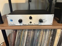
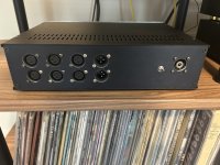
At the local market we got a Void Acoustics and my experience about the Void, high-quality sound, but something was missing, you could hear all the conversations of people on the dance floor, and the bass also made you feel a little bad, as if you wanted to vomit. Plus prices for a suitable setup are about 80k usd

Funktion-One - To achieve high-quality sound, you need to be able to tune this sound, I don’t think I’ll be able to find such a person in Thailand who can do it and on a local market i think there is no Funktion-One

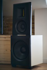
L-Acoustics - rented this sound for my event, liked the sound
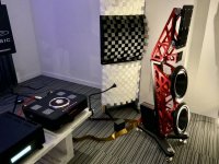
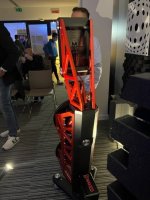
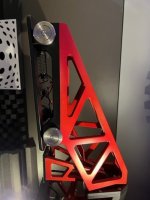
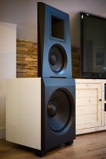
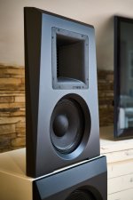
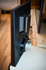
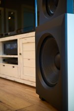
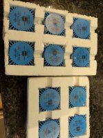
 Photo 1 Photo 2 (Photos from our event in Bangkok, underground basement)

I've heard that D&B and RCF also sound good

Turbosound - I read that Turbosound is more suitable for live performances

What I like about Funktion-One and Void Acoustics is their design, I like the massive sound that creates a positive impression on people. Perhaps there are some other brands with interesting designs?

I would also like to add that this is my first project to open a club, before that we only organized events in different locations and clubs, sometimes in completely empty ones, and rented sound and all other staff

What i need?

  • A good monitoring for a DJ
  • Quality sound system for the dance floor, the bass of which people will feel on their body in a budget around 30-50k
  • Easy to install and manage
  • Not difficult to maintain
I also have a couple of questions:

  1. I really like the look of the Funktion-One Skeletal, is it possible to install them for monitoring for a DJ if the entire sound system in the club is from another brand?
  2. What to do with subwoofers for a DJ in a small club, is it necessary to install separate subwoofers? Or how to make the DJ also feel the bass from the music he plays?
I am open to ideas an recommendations, if you have questions please ask them.

Any assistance / feedback / thoughts / memes / opinions are appreciated!

Thank you very much for reading and I hope to see you in Thailand on our dance floor!

  • Locked
JBL 075 to FaitalPRO HF10AK 16ohm

I have a pair of three way JBL Hartsfields with the 075 tweeter. I find that the 075 beams and can be fatiguing. Several sites recommend the FaitalPRO HF10AK 16ohm as a good replacement. My quest for the DUI experts it this, on paper the specs between the compression drivers seem identical. Can I just drop in the FaitalPRO with zero changes to the cross over?

Thanks!

Ham radio license study

Hello everyone. Was hoping someone might help me out here.

Yesterday I was introduced to some very small and portable ham radio transceivers. I'm interested in low power (QRP), wire attennas, and portability such as the Icom-IC705.

My question pertains to study prep. I've already found courses online but can someone suggest a good study book or other avenue that gets right to the chase. I've been over at ABE Books and it seems like the study guide questions are updated over time (like the USCG). Is this true so some books are outdated? Can I go straight to a General License and skip the Technician?

Thanks. Rob.

Monolith HTP-1 + Wilmslow custom design speaker + custom FIR crossover F/W

Sorry if I am posting an inapproprate place. This package includes:

  • A pair of crossover-free, 3-way speakers
  • A multi-channel processor/preamp with a digital crossover capability, with the crossover values already set for the speakers
  • Add your own favorite amps to the respective drivers.

It is priced at $5500, a fraction of a passive speaker pair with comparable driver configurations (ATC SCM50) for both the DSP crossover/surround processor AND the speakers. Local sale only. Ready for you to audition.

1. Speakers
  • Wilmslow custom-built 3-way floorstanders with bass reflex enclosure and front port (www.wilmslowaudio.co.uk)
  • ATC SM75-150 3" textile dome midrange + Scanspeak D2905/9500 1.1" textile dome + Volt B2500.1 10" pulp cone woofer
  • All 3 driver vendors are considered one of the best in the respective market. Their drivers are used in ATC, ProAc, PMC, Revel, etc.
  • Comparable driver configurations can be found in ATC SCM50 priced at $15999.99.
  • 3 pairs of gold-plated binding posts WITHOUT a passive crossover.
  • Direct connection between drivers and amplifiers enables very efficient operation, power and cost wise, and utmost definition in bass.
  • Mix/match your favorite power amplifiers to the 3 frequency bands/drivers with utmost flexibility
  • Detailed, transparent and neutral sound
  • Similar to Wilmslow Encore design, but no passive crossover and with ATC midrange instead of Volt's
  • Small bottom cavity for weight filling (currently some pebbles in it)
  • Bought in 2005, but rarely used in 2008-2010 and 2012-2020 due to my long commute to work
  • Overall cost over $5000 back in 2005.

2. Monolith HTP-1 16-Channel Surround Processor with Custom Crossover Added (https://www.monoprice.com/product?p_id=37887)
  • Best bang for the buck 16-channel surround processor with top-of-the-line AKM DACs, TI C66x floating-point DSP, and balanced outputs
  • Works as a surround processor + linear-phase DSP crossover for front left/center/right channels (see the note below)
  • Software Features: ATMOS, DTS:X, Dirac Live Room Correction, Auro-3D, Roon, BM, and all other standard features on HT pre/pros
  • Universal sound system controller supporting CD/DVD/BD audio, files on HDD, and streaming services
  • Can build a high-end movie/music surround system around this processor+speaker combo
  • Currently 9 channels are used for bass/mid/treble of front left, right center speakers.
  • 7 channels are available for left/right surrounds, front top, subwoofer, etc.
  • Bought in Dec'2020
  • Bundled with XLR->RCA adaptor cables for use with power amplifiers with RCA inputs only.
  • MSRP: $3999.99(without the custom crossover capability)
  • Custom crossover F/W
- Linear-phase FIR filtering with electric time alignment
- Special design for perfect reconstruction design
- Out-of-band suppresion over 110dB with 100+dB/oct. slope
- Crossover frequencies for front left/right/center channels fixed at 380Hz/3.8kHz, specific for ATC SCM75-150


IMG_8997.jpg
IMG_8995.jpg
IMG_8994.jpg
IMG_8998.jpg
IMG_8999.jpg
IMG_9002.jpg
IMG_9001.jpg
IMG_9004.jpg
IMG_9005.jpg
IMG_9006.jpg
IMG_9008.jpg
IMG_9007.jpg
IMG_9009.jpg

Arcam 8R amplifier non direct sound distorted

I have an Arcam 8r amp. It sounds ok when I have the direct button on for the speakers but when I click it off so I can use, bass, treble and balance it is all distorted.

What should I suspect of gone wrong please ?

I have 2 more so I can swap parts but if you can lead me to the right direction where to start.

Distortion is on both channels and I kind of hear the audio moving from left to right if o use the balance control.

Attachments

  • image.jpg
    image.jpg
    446.7 KB · Views: 73
  • image.jpg
    image.jpg
    609.2 KB · Views: 74
  • image.jpg
    image.jpg
    271.6 KB · Views: 64

Parasound D/AC 1000 output level

Hi all,

I received a "new" Parasound D/AC 1000 Dac based on PCM63 Dac chips, after comparing it to my other Dacs and CD players (AD1862 Diyinhk, Orelle DA188, Philips CD151, Yamaha CDX-630E) it feels like it's output level is much higher than all the others so I measured it's output level using a multimeter (Vac RMS) while playing 1khz 0db test tone and the multimeter shows 3.1 Vac out put while all my other devices measured around 2Vac (as they should).
I opened it's cover and it seems like that Parasound "over built" it in comparison to other Dacs that I have/had.
I have the Parasound Dac1000 schematics and I would like to know please how can I lower the output level to (standard) 2Vac output to match my other sources level.
There is a little difference in the Dac1000 that I have and the Dac1000 schematics, in the schematics the I out is connected to an AD744 opamp and in my Dac it's connected to AD841, and in my Dac there are no C304/C404, in the schematics there are 5534 opamps that are missing in my Dac but there are AD817 opamps.

Any help will be appreciated.
Thanks

Attachments

Need Help! YAMAHA CA-610 Main Filter Caps

i recently serviced my CA-X1 (ca-610) i replaced all transistors and recapped, upgrade preamp IC to OPA604, all parts from digikey and mouser, everythings fine but now i noticed that the VU meter lamp goes dim when theres a heavy bass i looked back to schematic then saw the lamp are directly powered by separate winding from the transformer, so then i concluded that when theres heavy bass reserved power from the filter caps (Nichicon 6800uF) was not enough so it pulls more juice from transformer therfore robbing the lamp thats why its getting dim, now i want to replace main filter caps but i dont have 10000uF caps but oddly enough i do have 2 13000uf caps im planning to install it then use a dim bulb as an inrush current limiter then bypassing it by a switch when the caps already charge, is 13000uf too much? im from philippines and i dont want to order 10bucks worth of caps and have 15 bucks of shipping fee..

Hello from european free party scene

Hello! My name is Alex, i leave in Brussels (Belgium). I run a sound system in France composed by Horn1850 & ES18bph (diy) & turbosound floodlight on top powerded by some FFA & Lab gruppen amp. Here in Belgium i ve compact stack of NCA audio powered by sanway & old qsc amp.

I m a huge fan of british & USA handcraft. I m really curious about "new" technology you use arround the world as Danley boundary coupled sub for example.
Most of my knowledge come from our national pride forum called "HORN PLAN" created by marc.O (MHB,MTH,MTL...). You definetly should go there and fine our very poor english speaking section 🙂

As there is only one international language: Music, evryone who are active on what we call "free party" can feel free to contact me.
I ve to apologise for my very very little english...
Sorry I m french 🙂

I m already impressed by the level of certain subjects &answer here, i would like to say a BIG THX to all contributors of this amazing forum.

Meratronik v640 vintage high impedance multimeter

Hello.
Anyone interested in an old polish multimeter?
It is in working condition and all manuals and service manuals are original.
It was state of the art high impedance at the time, with its high input impedance and accuracy.
It's battery compartment holds 12!!! AA batteries🙂 I put cables on for calibration.
It's a funny instrument, notice the build quality and the use of high quality 10 turn trimmers.
Its hard to put a prize on such instrument, if interested make an offer.
Ps all manuals are in English..

Attachments

  • 20240526_121436.jpg
    20240526_121436.jpg
    352.8 KB · Views: 114
  • 20240526_121450.jpg
    20240526_121450.jpg
    297.1 KB · Views: 124
  • 20240526_121521.jpg
    20240526_121521.jpg
    344.9 KB · Views: 126
  • 20240526_121544.jpg
    20240526_121544.jpg
    345.4 KB · Views: 126
  • 20240526_121745.jpg
    20240526_121745.jpg
    376.8 KB · Views: 124
  • 20240526_121612.jpg
    20240526_121612.jpg
    318 KB · Views: 124

Fault detectives, my logic and hypothesis to help with

Hello everyone,

I have had quite a few problems with my old ARC SP8 pre amp. ALL of these have been fixed with your combined help, so THANK YOU for your creative, smart, and knowledgable support.

Now the system has been sounding fabulous and I had got the levels of noise and hum to a very low level you could barely hear even at the speaker position.

BUT last night both speakers were accompanying the normal background low level noise with a (guess 100Hz) zizz, in both channels, and one that increased with the volume. The noise was independent of source, and was gone, not surprisingly, on mute. I had changed nothing in the preamp for quite a while, and it had been fault free for 18 months or more I would guess.

I swapped out all the valves including the power supply ones, and the zizz remained.

I did a very quick check on voltages around the valves and power supply and they all seemed as usual, I should repeat more carefully.

Music plays as normal, accompanied by zizzz

I don't own a proper oscilloscope but I have done some testing cheating with REW software recording before.

So my thought are as below:

  1. Zizzz 100Hz is likely from power supply
  2. if it is in both channels and independent of input it is more likely power supply
  3. I should start looking at capacitors first (in the power supply)
I could just swap the small caps in the power supply and hope for the best?

I have already changes a few and also when sorting a problem with the phono stage so there are not that many left.

Any thoughts welcome 🙂

Nakamichi AV1 repair

Hello all
I hope this is the right place to look for a repair service (commercial recommendations or a hobbyist) in Kent, UK. Please mods move or delete it if not.

I have one of these AV processors with an AVP1 amp but the other day it clicked off and is dead, no light on the standby switch. I checked the plug fuse and IEC socket fuse and both are fine so I suspect a power supply problem. I looked inside and nothing is obviously fried but that's as far as my diagnosis ability goes at present.

If someone local is willing to have a look I'd happily pay for their time or make a donation to their chosen charity, or if anyone can recommend a repairer in north Kent I'd be really grateful.

I know these units are cheap when they turn up but I hate throwing things away.

Thanks

Steve

Help for a 90 liters sealed subwofers

Hello, I ask for help here. I am currently happy with the sound of my pair sub diy subs. I used a 90 liter sealed box with a Hypex FA 501 500w 4 ohm module and a Scan-Speak Discovery 30W/4558T00 Subwoofer. However to get a long response below 50hz at high volume, scanspeak suffers and is close to its physical limit. I would like information on other 12” speakers that will fit into a 90 liters sealed box, preferably 4ohm capable of going down to 30hz comfortably. I listen to all the options although I prefer not to exceed 500 eur per unit. The crossover frequency used can vary between 80 and 40 hz to reinforce a 10” wofer from my loudspeakers. If there is already a topic like this, I apologize and accept the link.

BR
Toni
  • Like
Reactions: Subuckethead

Help with vintage pre-driver TO039 transistor replacements

Hi everyone. I have a Panasonic quad receiver with one channel blown. I've placed an order for the outputs replacements (originally 2SD217), substituted by MJ21194G, but there's a couple pre-drivers (TO039, gold plated leads) I can't find replacements for.

These are:
  1. 2SC696A (NPN, 0.75watts, 100Vcb, 60Vce, 35 MHz)
  2. 2SA546A (PNP, 0.75watts, 90Vcb, 80Vce, 50MHz)
The alltransistors website replacement search yields nothing for me, but a list of obsolete devices.

20240526_025924.jpg


Appreciate any help.
TIA, Tom

Change A 6L6 400 volt amp to EL34 tubes?

Ive started building with a 400 volt PT 6L6GC PP amplifier for a guitar and I was thinking about changing the power tubes to EL34 tubes and keeping The 6L6 tube rectifier A 5U4GB ?, My question is this; Is it going to be enough power for the tube swap ? . And Should I get rid of the rectifier tube ? . My donar is a 1960 Whirlizer 501273 organ Amplifier. 501426 PT and a 500882 OT . And For The Pre Amp section I was going to copy The Original Sunn Model T. I'm building a pretty thick Aluminum chassis for it right now. I have it made already but it still has to be Tig welded together. I'm trying to get a hand sensitive deal going with this thing. Just Looking for a few ideas before I start assembling it and I actually start cutting into the new chassis. I have already tested the transformers and everything looks good with both of them. The negative bias is A little bit weird it's using 1/2 of A 12AX7 tube. It took me a little while looking at it to figure that out. I'm New on here. Hi to everyone !

Rockford T1000.5

Hi I have a Rockford T1000.5. I has no output, it powers up but makes a buzzing noise and all the clip lights are flashing. I checked all the fets and no issues. I found a 1uf capacitor with a hole blown in it. I removed it from the circuit and I’m waiting for replacement to arrive. I checked the square wave on the ps fet and it start off fine for two seconds then it turns to the monstrosity in the photos. Im thinking there is an issue with the drive IC. Thoughts?

Attachments

  • IMG_1481.jpeg
    IMG_1481.jpeg
    760.5 KB · Views: 77
  • IMG_1480.jpeg
    IMG_1480.jpeg
    773.1 KB · Views: 74
  • IMG_1477.jpeg
    IMG_1477.jpeg
    458.3 KB · Views: 72
  • IMG_1472.jpeg
    IMG_1472.jpeg
    381.5 KB · Views: 69

POTENTIAL FAKE PCM56P -SAME SERIAL NUMBER?

Hello guys, hope you guys doing well.
i recently purchased a simple board from china, it came with PCM56P with same serial numbers, idk how Burr-Brown printed their batches but for me they look like potential fakes or china Used rebadged for cleaner look... it comes from the company BRZHIFI. here i send a pic since i couldn't find much info on this chips.

My question is, what are your thoughts, fakes, or if you have experience, where could i find real ones?
Thank you.

20240525_154915.jpg

Plans to try to revive Dynaudio C1 Platinum after system is devastated by flood

Guys, I suffered seriously with the flood at the end of April here in Brazil, my audio system was devastated by the waters and a lot of mud.

My technician managed to recover the electronics, now I'm trying to decide what to do with the speakers, the main ones are the Front ones.

The wood of the boxes opened, I didn't notice it swelling, the sides warped and the plate also suffered some damage but is essentially intact.

I have the option of sending everything to a person qualified for this type of repair, then he can decide whether it's worth repairing the wood or making a new cabinet, but he's on the other side of the country and I honestly don't have much confidence in him, I met him through a recommendation.

My question is, wouldn't it be worth reassembling them here? Try to untwist what was bent and see how it will play?

Crossovers, speaker and tweeter are intact, my technician checked everything.

Below are some images and video of what the wood of the speaker looks like.

Here is the video of the woods:

Login to view embedded media

Attachments

  • IMG_1659.jpeg
    IMG_1659.jpeg
    274.9 KB · Views: 102
  • IMG_1655.jpeg
    IMG_1655.jpeg
    322.7 KB · Views: 107
  • IMG_1654.jpeg
    IMG_1654.jpeg
    434.3 KB · Views: 115
  • IMG_1619.jpeg
    IMG_1619.jpeg
    908.1 KB · Views: 105
  • IMG_1618.jpeg
    IMG_1618.jpeg
    913.9 KB · Views: 118

Ambient noise floor due to insects

No outdoor ground plane measurements this month, not in my region of North America... It is cicada season https://en.wikipedia.org/wiki/Periodical_cicadas, and 10 million of these loud little buggers per acre makes for some loud ambient background. This afternoon, I measured 86 dBA continuous in my back yard. It is an octave wide band going from 4k to 8k... very annoying. The only way to escape it is to drive several hundred miles...

So I am wondering about other parts of the world... what sort of natural phenomenon creates high ambient noise levels in South America, Europe, regions of Asia, Australia, Africa, etc... j.

Building custom tube amp from scratch

Howdy! I'm new to the diyAudio forum, and I wanted some advice on building myself a general-purpose audio amplifier. I intend to use it with microphones, guitars, radios, etc.
The tubes I plan to use with this are the 12BA6 pentode as a driver, and the 35C5 pentode as a power output tube. I was going to pull a transformer from some old power supply to use as the output transformer. Any tips?


Snapshot_20240525_3 2.JPG


Snapshot_20240525 2.JPG


Snapshot_20240525_2 2.JPG


Snapshot_20240525_1 2.JPG

Power Transformer Primary CT Confusion

Hey there,

I have a question about center tapped primaries on used, old-style PT's.

The transfrormer in question has a black start, black/yellow ct, and a black/red end.

For 120v mains, should I use the black and black/yellow, or black and black/red?
Could I hook up a signal generator to the secondary and gleen something from the primary that way?

When I first bought it, I thought it had 2 primary winding you could put in parallel since there is a white lead, but it turns out that the white wire is the bias tap on the secondary 😵.

6AU4GTA heater voltage problem

Long story short:

I'm struggling a bit with the power supply for my 808 SE amp. The first power transformer I tried (AnTek toroid) both vibrated and produced a too low HT so I replaced it with an old EI transformer from a 1940's cinema amp. My mains voltage is 230-235V and the transformer has taps for 220 and 245V. The 220V tap results in the right heater voltage for the 4x 6AU4GTA rectifiers but the HT gets a bit on the high side while the 245V tap gives a more comfortable HT (and less mechanical noise) but only 5,8-5,9V to the rectifier heaters.
How important is this in the real world? The datasheet mentions 6,3V +-10%, that would be 5,67V for a minimun.

Central Heating

I have replaced an old programmer with a newer model.
From programmer (downstairs in pantry) to junction box (upstairs under floorboards) is a cable, 3+E.
Cable is:
Earth (bare)
Neutral
2 x switched live.

For the new programmer to work correctly I need one more switched live.
It would be a major headache to run a new cable.

Is there anything I can do using existing cable?
Example:
Take Earth from another under floor cable to free up a core (Earth core is bare so probably dangerous - it wouldn't be double insulated, only the outer grey sleeve).
Take a Neutral from another under floor cable to free up a core (is it safe to have live & neutral feeds in different cables?)

TL using a B200, Phillips dome and T27

About 40 years ago I built a transmission line speaker using the b200, a Philips dome for a midrange and a t27 tweeter. The design was a kit from a place called Gladstone Electronics, in Toronto, Canada. I loved them. The speakers and the information are long gone. I have been scanning the internet to try and find out about the kit. I am considering trying to make them again. The system was based on a UK magazine that had the diy instructions . Any help appreciated!

LM3886 vs Marantz PM6006

Hello. Silly question. I have a hobby of building some audio circuits. Thinking about building an amp with LM3886 and Rod Elliott P88 preamp.
Could it compete in sound quality and technical specifications with my Marantz PM6006?.
Of course leaving aside the Marantz's digital input options. Just comparing the sound quality.
Can someone tell me what Damping Factor value of the LM3886?
Greetings

Anyone tried this mid driver?

Came across this new mid driver from B & C, the DCM 420. Specs look very good & the price is not too bad.

I found this while I was about to order a pair of DCM 50's, which are for my build of a pair of Belle Klipsch's. I've used the DCM 50 before in a similar build & really liked the sound of them, but see that the 420's are a fair bit less expensive, so wondering if anyone has ever heard them.

For Sale Mundorf Silver Gold caps

Used but in good condition.I buy this some years ago by HiFi Collective where I buy almost all my stuff.All contacts are ok and are minimum 40mm long.Plese look on the pictures.For more info or offer plese contact me.
The buyer will become :
2 x 3,0 uf silver gold
2 x 0.82 uf silver gold
So all 4 caps for 150 euro including shipping inside EU or best offer.

Attachments

  • 20240502_223108.jpg
    20240502_223108.jpg
    1.1 MB · Views: 149
  • 20240502_223113.jpg
    20240502_223113.jpg
    1 MB · Views: 154

More Beveridge News

I have been having an ongoing saga with my Beveridge 2sw-1&2 ( the "2" having the tone switch on the input). I have had much conversation with a good member here @cvanc and he has been a good mentor.

I have had these for just over a year and they sit for weeks or months as I get inspired or not. When initially rebuilt (see my other threads) the dc voltages were all within reason. However, I soon discovered that both amps suffered from what was to be oscillation manifested by white type hash noise on the program material and sometimes wildly going off and driving operating current up and blowing fuses.

Over that time , lots of hair pulling, ferrite beads wire routing and the like proved to have no effect. I am pretty competent around tube electronics but I have a healthy respect for these as trials take longer as safety is paramount for me.

In the end I have zeroed in on the power transformers in both these units as being faulty - perhaps modulating and beating through the different windings and causing the oscillation. Both units came to me in operable condition with blown apart tubes in one and popped caps and rectifiers in the other. These ran away at some point.

I had new transformers wound with a bit of experimentation to arrive at the final design. One for both heater supplies and preamp board 60v and one for the high voltage. I am going to do further experimentation but right now the new transformers totally clean up the oscillation.

The yellow trace is input and purple and pink traces are at the +3200 and mid point --- see before and after.

Other news is that I picked up a packet of old Beveridge correspondence files that would of been to a dealer from the factory in the 1976 - 1979 timeframe. Lots of interesting back and forth in the letters contained in this file along with griping and thoughts on a review from
J Gordon Holt of Stereophile magazine. In that packet was what looked like an original blue print schematic and the 2x positive for the preamp board PCB.

In my quest to isolate the source of oscillations I managed to track down a quantity of original spec Toshiba PNP S1376 driver transistors directly from Japan that were part of the original boards back in the day. I can confirm that the substitute Central Semiconductor CEN-U57 works as well - its available from Mouser and Digikey for the moment and has original pin out ECB as well.

A few more experiments to follow in this maddening journey.

Attachments

  • Like
Reactions: cab

The future?

Soon maybe one can put all DIY amplifiers and speakers into good use 🙂

My question to ChatGPT:
Would it be possible to process music recordings with AI in order to separate for example vocals, drums and other instruments into separate channels?

ChatGPT:
Yes, it is indeed possible to use artificial intelligence (AI) techniques to process music recordings and separate different elements such as vocals, drums, and other instruments into separate channels. This process is known as source separation or audio source separation.
There are several AI-based algorithms and techniques that can be used for this purpose, including:
  1. Deep learning-based methods: Deep learning models such as convolutional neural networks (CNNs) and recurrent neural networks (RNNs) can be trained on large datasets of mixed music recordings and their corresponding isolated tracks to learn how to separate different sources.
  2. Non-negative matrix factorization (NMF): NMF is a technique commonly used for audio source separation. It factorizes a mixed spectrogram into the product of two non-negative matrices, each representing the spectrogram of a separate source.
  3. Independent component analysis (ICA): ICA is another popular method for audio source separation. It aims to find a linear transformation of the observed audio signals such that the resulting signals are statistically independent.
  4. End-to-end deep learning models: Recently, end-to-end deep learning models have been developed that can directly separate mixed audio signals into their constituent sources without explicitly decomposing the signals into spectrograms or other intermediate representations.
These techniques have been successfully applied to various audio source separation tasks, including separating vocals from music accompaniment, isolating individual instruments from ensemble recordings, and separating drums from other instruments in mixed tracks.
However, it's worth noting that audio source separation is a challenging task, and the quality of the separation results can vary depending on factors such as the complexity of the audio signal, the quality of the recordings, and the specific algorithm or model used for separation.

Upgrade JBL GTI800 - add magnets and change spiders

Hi all.
I have such drivers.
I decided to run them as midbass, 65-250 Hz.
And from this point of view, improve.
I'm not the first owner. The first one repaired, changed the caps (these are decorative parts) and spiders (but this is important). Perhaps the spiders are original or close to them. I did not send the drivers for measurements.
But I decided to improve them.
I know of a great many experiments with additional neodymium, which is either placed on repulsion to the driver magnet, disk, or attached around the main magnet. In all cases we have a decrease in Q factor and an increase in sensitivity. Increased sensitivity is always a plus, better sound.
The second modification is replacing the spider with a more rigid one. Because I only need midbass from the drivers. I know about the successful experience of the Rainbow company, in their line of vanadium, pro and slts, there were two types of woofers - one classic, they played up to like 53Hz, the second were kick woofer - and played 80-180 Hz or 80-220Hz, depending on what is written where . The only structural differences between them were in the puck, the spider was stiffer, and in the parameters - the kick-woofers had a higher Q factor.
I searched for information on Google for several days. Including many old topics I found here on the forum.
An additional magnet gives an increase of up to 3 dB; if used around the main magnet, neodymium gave up to 10 dB, but the effect is more pronounced the weaker the main magnet of the driver. The 800s have a large magnet. So is it worth the effort?
If the experiment is successful, I am going to extend the idea to mid-frequency drivers and woofers.
Does anyone have positive experience with this, and in general, what are your thoughts on this? I will be grateful.
  • Like
Reactions: GM

Best way to attach cones with foam around screw holes?

Hey all
I’m nearly done with my 2 way speaker with x2 faitalpro 8fe200 and a hf100 CD with sth100 horn!
I’m decided on wood screws to screw the cones into the box, but I’m not sure if I should use silicone sealant with the hard foam around the outer circumference of my woofers, or just screw them in/ use blue tack? I’m assuming I should use it on my metal horn.
Photo attached of said foam🙂
Thanks in advance!
image.jpg

KEC Transistor Data Sheets

I've seen KEC brand transistors in new equipment but am unable to find data sheets on them.

I'm currently looking at the Sherwood 4109 receiver and the darlington output devices are:
2SD1510
2SB2510

The 2SD1510 shows up as a Panasonic darlington but it is in the wrong package and is clearly not the part.

Here is the web site for the company:
KEC

Thought to look under darlington on their own page and I think that I found them under KTD1510:
http://www2.kec.co.kr/data/databook/pdf/KTD/Eng/KTD1510.pdf

and KTB2510:
http://www2.kec.co.kr/data/databook/pdf/KTB/Eng/KTB2510.pdf

Look to be copies of Sanken parts.
Seems I answered my own question but I'll post this anyway in case anyone else is looking.
  • Like
Reactions: miguelnoda

Seeking Quiet Class D Amp for High Sensitivity Horn Drivers

Is there a concensus on what is currently "the best" class D amplifier boards? Specifically "best" for low noise. And availability from reputable sources would be a big plus for me!

I built some active speakers featuring pro audio coaxial drivers, and the horns are extremely sensitive, which means noisy. The horns are rated at 106dB, and they currently have a massive pad on them to cut the noise to a tolerable level. But it is still there.

So I would like to build a class D amp that is extremely quiet. At a minimum I'd like to build a 2 channel 30+ watt amp in a 1RU form factor with balanced inputs.

I would be interested in buying a ready made unit, but I haven't found one. I really do want the 1RU form factor and balanced inputs. And I want as much of a guarantee as possible that the amp will be genuinely quiet, suitable for high sensitivity drivers.

Depending on cost and availability, I may want to make it a 4 way amp, with 2x 30watt + 2x ~100 watts. (My mids are 98dB sensitivity, so they are also a bit noisy and require a pad to tame them...)

My current amp is a multichannel emptiva xpa gen 3 (class H).
  • Like
Reactions: head_unit

Finalising speaker design, Crossovers, Time alignment, Hypex FA253

Hi All,

I've just finished designing and assembling a 3 way sealed active floor standing speaker using
12″ SB34NRXL75-8
6½″ SATORI MW16TX-4
SATORI TW29BN-8 Beryllium Tweeter

It's running off a Hypex FA253, so crossovers and dsp etc all done through there.
It's my first time properly using Rew and the first time using the Hypex amps.

I'm at the point where i have preliminary crossovers done, all 4th order LR to get me started.

I've been trying to work out how to use Rew properly to do time alignment of the drivers.
I know I need to use the timing reference options, but the loopback etc just confuses me.

I bought a UMC202HD & EMM-6 mic, so i have the dual channel input/output and the XLR mic.
I'm not sure how to wire it up proper to look at driver timing alignment.

Has anyone got the same/similar gear that can offer some guidance?

Thanks heaps!

UAC-1 FIFO USB audio interface

It's a usb audio interface use UAC1 way , different from normally synchronous or asynchronous ,It‘s use synchronous mode and a big FIFO .

The UAC1 interface has two OSC (22.5792 and 24.576MHZ)for audio ,and a NDK 10MHZ OCXO for MCU work (STM32H7B0).

There are RCA SPDIF output ,HDMI(I2S over HDMI)output , four SMA output DATA/LRCLK/BCK/MCLK .

Because of UAC1 mode,it only supports 44.1/48/88.2/96KHZ PCM,but much more better than many UAC2 machine ,I use it to listen apple music ,is very suitable.


6.jpg


3.jpg


5.jpg


7.jpg


4.jpg


2.jpg


1.jpg
Projects by fanatics, for fanatics
Get answers and advice for everyone wanting to learn the art of audio.
Join the Community
507,719
Members
7,885,685
Messages

Filter

Forum Statistics

Threads
406,114
Messages
7,885,685
Members
507,719
Latest member
LiamJersey