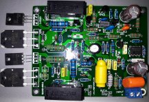
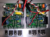
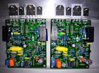
I am starting to setup my QUAD 405 V2 clones (pictured). Does anyone have the pictured boards and can offer advice or suggestions?
From my searches and reading I gather that there are a couple of main modifications to consider:
In addition to the above I was thinking of a couple other possible modifications:
Later I might give my capacitance multiplier another try and use it with this amplifier after replacing the TIP142/147 again.
From my searches and reading I gather that there are a couple of main modifications to consider:
- Replacing the TL071 with the OPA134
- Replacing the green 2W 560 Ohm resistors with larger resistors and spacing them away from the PCB.
In addition to the above I was thinking of a couple other possible modifications:
- I see pictures online of 2SC2922 based clones so I am considering using some of my genuine 2SC6145. (The closest I have.) Any warnings/suggestions? I am using +/- 40V supplies and 4 Ohm speakers.
- The TL071 operational amplifier is powered from 3.3k Ohm resistors and 15V Zener diodes which are bypassed by 0.1uF film capacitors. I am thinking of adding 10uF Panasonic electrolytics or 10uF Monolithic ceramic capacitors under the 0.1uF. Does anyone have any suggestions? My 40V supplies might be a bit high to try replacing the 3.3k Ohm and Zener diodes with LM7815/LM7915 with their 35V absolute maximum rating. Perhaps with 3.3k Ohm and the 10uF the PSRR of the operational amplifier is more than sufficient?
Later I might give my capacitance multiplier another try and use it with this amplifier after replacing the TIP142/147 again.
Attachments
So far I have listened to the stock configuration for several hours and then added the additional bypass capacitors for the operational amplifier supplies. Both configurations sound very nice. This amplifier definitely has a different characteristic for low to mid volume passages and solo instruments. It definitely has a nice Class A characteristic evident on solo instruments and vocals, for example.
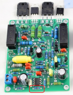
I have noticed that the gain is rather high and after reading the Quad 405-2 upgrades page (which also mentions the OPA134) I see that this Quad 405-2 clone uses the original 330k and 22k resistors for the gain. Thus the input sensitivity is rather high. Currently gain is x15 and I am planning to reduce it to x4.6, see Quad 405-2 upgrades
I plan to add a 1/4W 150k 1% metal film resistor to the underside of the 330k resistor (circled in red in the attached photo) to bring the parallel value to roughly 100k. Has anyone performed this gain (reduction) modification to this particular Quad 405-2 clone (LJM)? If so, successful or any warnings before I proceed?
Attachments
Last edited:
I have partially completed the gain modification with the operational amplifier feedback resistor modified to 100k (150k in parallel with the stock 330k) and the capacitor in series with it modified to 147nF (by placing 100nF in parallel to the stock 47nF, on the back).
I still need to finish the gain modification with a 33uF electrolytic which I will need to order. I could temporarily use 10uF in parallel with 22uF but to be neater I will wait to get 33uF.
I still need to finish the gain modification with a 33uF electrolytic which I will need to order. I could temporarily use 10uF in parallel with 22uF but to be neater I will wait to get 33uF.
Attachments
I found 22uF UES and 10uF Silmic left over from modifying the DAC inside an AVR-3805 so I went ahead and finished the gain modification. The 22uF UES is on the top of the board and the 10uF is under the board. A little unusual combination but it did not involve waiting to order 33uF.
I know many of the QUAD405 related posts are in 2007 era threads but I am hoping some of the QUAD405 fans are still around to comment and make suggestions.
When I get around to ordering operational amplifiers I will likely try the OPA134 in place of the TL071. However I was wondering if anyone has ever tried a Ti NE5534 or Fairchild RC5534 successfully in a QUAD405 (Mk 2 or V2)? Does the potential output offset issue essentially rule this out?
Attachments

Last edited:
I've used NE5534 in real Quad 405s. You get a bit more DC offset, but how much is too much is up to you. Nothing that alarmed me, maybe 10mV. You also get a dying squeal unless you bypass its rails wih a large electro, say 220uF.
A real 405 runs on 50V rails, not 40V. You are only getting 54 watts out of a 90 watt amplifier.
A real 405 runs on 50V rails, not 40V. You are only getting 54 watts out of a 90 watt amplifier.
ejp; said:I've used NE5534 in real Quad 405s. You get a bit more DC offset, but how much is too much is up to you. Nothing that alarmed me, maybe 10mV. You also get a dying squeal unless you bypass its rails wih a large electro, say 220uF.
Thank you for the reply. I have 47uF Panasonic "M" series bypasses under the board as shown in the photos earlier in the thread. I can bump those up to 220uF if you recommend. Is that how you bypassed yours?
ejp; said:A real 405 runs on 50V rails, not 40V. You are only getting 54 watts out of a 90 watt amplifier.
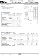
So my speakers are 4 Ohms and the clone uses D1047 outputs. I wonder if those "K" D1047 quite possibly are not really KEC D1047 but instead are clones. (Clones of clones of the Sanyo D1047?) Anyways, I did not think 50V was safe for 4 Ohm speakers with a single pair of D1047. I have attached the beginning of the KTD1047 datasheet to explain some of my caution. It is not one of the bigger output devices and it is targeted more towards 60W amplifiers. Do you think 50V is the best supply voltage even if I have 4 Ohm speakers?
I have a transformer that would give me 53V however I wonder if I need to bump up the SOA of the output transistors first. I have genuine Sanken 2SC6145 (160W devices) but I have not tried that yet. I am cautious because I don't want to create stability problems with this somewhat less straightforward design.
I wonder if anyone out there has successfully used genuine Sanken outputs on this design? (Without stability issues.)
Attachments

Last edited:
I use MJ15003 in 405s.
With this clone I might need to use something like NJW3281G, 2SC6145, TTC5200 or 2SC5200 before pushing the rail voltages higher. I just don't know if that is going to create stability problems. Those are all faster devices.
You want the drivers faster than the power transistors in this design.
The drivers in my clone are KTA1659A which are specified as 100MHz Ft. So that is faster than all of NJW3281G, 2SC6145, TTC5200 or 2SC5200 (even the 60MHz 2SC6145).
However I don't know if that means 2SC6145 would be stable. Perhaps TTC5200 is a reasonably safe choice? 2SC6145 would be nice (if stable) since it might be more robust for 4 Ohm loads.
Attachments
Why might you need to used anything other than MJ15003?
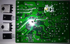
These clones do not use TO-3 metal cased transistors. Instead they use TO-3P (plastic) transistors as shown in the attached image.
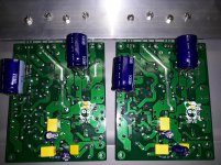
The LJM clone of the original QUAD405 (Mk 1 or V1) is available with either TO-3 or TO-3P boards. The LJM clone of the QUAD405-2 (Mk2 or V2) is TO-3P only.
In general TO-3P works well for me since I am using recycled AV receivers as sources of chassis, transformers and heatsinks.
Attachments
I've used NE5534 in real Quad 405s. You get a bit more DC offset, but how much is too much is up to you. Nothing that alarmed me, maybe 10mV. You also get a dying squeal unless you bypass its rails wih a large electro, say 220uF.
Sockets are now installed and the Ti NE5534 appear to be perfectly happy and stable with 47uF Panasonic "M" series soldered on the bottom of the board along with 0.47uF PP film capacitors for bypassing. These were assembled boards with no sockets for the operational amplifiers so removing the Ti TL071 was a little tough but eventually I removed them without damaging the boards.
I think the gain (reduction) mod improved the amplifier by making it easier for the TL071. The NE5534 version sounds very good. I am getting about 21 mV offset on both channels but I think that is "ok".
Attachments
Gain reduction improved the amplifier by providing more NFB around the opamp. 'Making it easier for the TL071' doesn't really mean anything. It still does the same thing as before: it just has less nett input to work with.
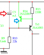
I read on Keith Snook's QUAD405 page about improving the current source by removing C5 and adding a second PNP (see the two arrows in the first attached photo).
I was wondering if that would be better, worse or basically equivalent to leaving C5 and improving the current source by replacing R14 with a red LED and then adjusting the value of R15 (see the two arrows in the second attached photo).
Which would be the best approach? Which would make the better current source?
Attachments

Hi @kozard, just ordered a kit like yours. I am really interested to hear how this famous topology is sounding. I have Dynaudio 4 ohm speakers and only 35V DC per rail. Looking fwd to arrive and hear it. I would like to fit more powerful transistors or maybe to parallel another 2 of them on the old ones. Will see....
I found that the OPA228 works well in this kit. Just that and the gain reductions works very well. (Solder bypasses directly to the opamp socket pins and the ground plane if you change the opamp. Something like 0.1uF film plus 10uF to 47uF electrolytic.)
[It does sound good stock also.]
[It does sound good stock also.]
I've done the 'second PNP' style current source on my genuine 405-2 boards to good effect, it eliminated any audible mains hum, and as a bonus no longer relies on the electrolytic C5 for rejection. I think I used 180R for R15 to stay closer to the ~4mA source current.I read on Keith Snook's QUAD405 page about improving the current source by removing C5 and adding a second PNP (see the two arrows in the first attached photo).
I was wondering if that would be better, worse or basically equivalent to leaving C5 and improving the current source by replacing R14 with a red LED and then adjusting the value of R15 (see the two arrows in the second attached photo).
Which would be the best approach? Which would make the better current source?
Your LED suggestion will drop the emitter voltage of TR1 such that its E-C headroom will be squeezed due to the fixed voltage at TR3-base.
One addition I made to this was to leave some resistance in the R14 position (extra PNP emitter-collector), as without it the power-off behaviour gave a speaker thump, whereas with it the characteristic was similar to before. I can dig out the simulations I used to show the comparison of the curent source bahaviour in each case.
Other than the gain reduction and OPA134 replacement that you propose, I also replaced TR3 and TR4 with MPSA92 higher voltage devices, which then meant R23 could be removed and C11 replaced with a link.
- Home
- Amplifiers
- Solid State
- QUAD 405 V2 Clones - Suggestions or Experience?