The added op-amp bypass caps are connected to the op-amp socket V+ and V- pins and then the larger copper pattern which is the input ground.
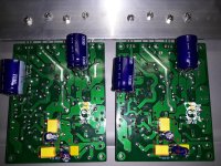
I think a picture is best to clearly explain. The red boxes enclose the added op-amp supply bypass capacitors. The red G is the larger copper pattern which is the input ground.
I used 47uF and 0.47uF because I had them. I don't necessarily know if 10uF or 22uF (etc) is really any better or worse. But 10uF to 47uF should be much better than nothing at all.
The other two components (the resistor and capacitor which are not boxed) are added for the gain modification.
In this picture you can also see the two large added main power supply bypass capacitors.
Attachments

So there are several different things going on:
1. The simpler issue is replacing existing capacitors with better ones that are on-hand. If it is a 100nF or 0.1uF bypass on a supply then I would use a good quality 100nF or 0.1uF polypropylene as a replacement. WIMA is considered a very good choice. I often don't have any extras left around so sometimes I have used lesser but still polypro models.
2. The op-amp has zener supplies but no bypass capacitors. So I added 47uF Panasonic M and 0.47uF polypro capacitors as bypasses. Pana FM are even better and WIMA would be great too. If one has the money and this is a priority hobby then it is sometimes nice to pick the best components. 10uF and 0.1uF might be perfectly ok too.
3. The gain change where I modified the resistors and scaled the capacitor in the signal path. For this I would refer you to the sites dedicated to the 405 modifications for explanation and details.
I tend not to use ceramic capacitors due to piezo electric effects, voltage coefficients, etc. Polypro is much better and affordable.
Also my board arrived with the lesser quality yellow film caps but the better driver transistors. I suspect your orange film capacitors are better than the yellow caps. Perhaps different vintage boards or clones of clones?
Thanks! The clone boards have an obvious difference from any other quad boards I have tried, in that they have a ‘ GND ‘ connector at the centre of the board. Do I connect this to the mains earth?
I believe LJM (designer of this clone) intended the Vcc and GND tabs to be connected back to his LJM power supply board which contained both the power supply and the speaker protection relays.
As for safety aspects and proper grounding there are good tutorials available and it is not a subject for quick answers.
I would suggest that you research those amplifier grounding and safety tutorials and follow a known good example. It is worth doing this carefully.
I also strongly suggest that you use a quality power supply board and quality speaker protection board.
Thanks! You are decoupling the opamp by soldering a cap, one on opamp V+ and another cap on V-, and the other end of the caps goes to the input ground.The added op-amp bypass caps are connected to the op-amp socket V+ and V- pins and then the larger copper pattern which is the input ground.
I noticed the third pin down, on the right hand side of the opamp, which is labelled as +IN, this also seems to go to the input ground ? So could I solder caps across the opamps, one cap to V+ , the other cap to V-, then the two remaining cap leads opamp +IN to get the decoupling
Thanks ! I noticed on different hardware, manufacturers connect a cap across the V+ and V-
Is this an inferior way of decoupling
Is this an inferior way of decoupling
I use two capacitors. Here is one explanation:
https://electronics.stackexchange.com/questions/187806/do-op-amps-need-one-bypass-capacitor-or-two
https://electronics.stackexchange.com/questions/187806/do-op-amps-need-one-bypass-capacitor-or-two
If the output load is primarily to ground, then two capacitors. If it's to either supply, then one capacitor will suffice.
The purpose of bypass capacitors is to provide a low-impedance close to the chip (bypassing any series inductance to the supply rails). Since most op-amps do not have a ground pin the internal circuitry does not care about the ground level, however when you apply a load to ground the current path is from the positive or negative supply, through the circuitry on the chip, out the output and through the load to ground. A capacitor from the positive and negative supplies will make sure that loop is physically small and thus low inductance.
Thanks! Just wanted to pick your brain about removing the current limiting circuit mentioned earlierIt is the negative side (not the positive side) of the input which connects to that signal ground.
Just connect the capacitors to that island of copper I labeled as "G" (input ground) and then the +/- pins on the op-amp socket.
The current of the 405-2 is supposed to be limted to 8 amps, what would removing the current limiter raise it to, and would it affect the bass only.
8 amps does not sound too bad, would having more current be a good thing, would it have a positive impact on the sound quality
What impedance speakers are you driving? What output power are you typically driving the speakers to? (Have you ever taken a look at the output voltage either with a scope or even just a rough rms measurement with a meter?)
Do you have information the sensitivity of the speakers and how far away they are from you?
Do you have information the sensitivity of the speakers and how far away they are from you?
The speaker are 8 ohms impedance, Power output to speakers is 10-20 watts per channel. Speaker sensitivty is 89db/1 watt/ 1 meter, and speakers are placed 10 feet away from me,
So very quickly with 8 Ohms speakers and 10 or 20 watts you are at quite a bit less than 8 amps. Strickly from a current limit perspective you should not be activating the current limiter. Are your values measured values? Peak or average? Have you measured the SPL at your listening position with 10-20 watts?
I have read that some remove the current limiters because of concern that it affects the sound. I have not removed the limiters and I don't know what impact that has on the sound either perceived or measured. I will let someone else (who has tested with and without limiters) share their measurements and impressions of what removing the limiter does on a QUAD405-2. I am curious also about what the hypothesis is (regarding the circuit function) and what measurement and listening reveals.
I have read that some remove the current limiters because of concern that it affects the sound. I have not removed the limiters and I don't know what impact that has on the sound either perceived or measured. I will let someone else (who has tested with and without limiters) share their measurements and impressions of what removing the limiter does on a QUAD405-2. I am curious also about what the hypothesis is (regarding the circuit function) and what measurement and listening reveals.
Power output of a Quad 405 is over 90W/ch. ‘10-20’ is just vague. At 20W into 8 ohms you have 1.58 amps.Power output to speakers is 10-20 watts per channel.
Thanks! I have read on a few of the other forums that quad's implementation of the current limiting circuit does degrade sound quality, but cannot find any before and after testimonals of how the sound actually changed
Well it would cause clipping if triggered, but you’d have to be running at near full output to get that, and yes it is indeed curious that nobody ever says what it sounds like. If you have a 405-1 do the Ludwig mod with the 36V Zener. If you have a 405-2 just leave it alone, or remove the network to see whether you can hear a difference.
check out this thread:
https://www.diyaudio.com/community/threads/quad-current-dumping-class-a-output-power.406673/
https://www.diyaudio.com/community/threads/quad-current-dumping-class-a-output-power.406673/
- Home
- Amplifiers
- Solid State
- QUAD 405 V2 Clones - Suggestions or Experience?