Hi Everyone,
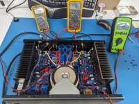
A few weeks ago I rescued a broken, neglected, and abused GFA-5300. I now have the amp working, but can't get the DC offset adjusted to spec, and am hoping for some help on next steps.
To get the amp to this point I did the following:
Plus some bonus stuff:
With those tasks complete, the following good things happen:
Unfortunately I can't get the DC offset adjusted correctly. I'm measuring with the amp warmed up, no load, and the inputs shorted. Instead of no more than +/-10mv (per the service manual), I'm getting 60mv on the right channel and 110mv on the left with the trim pots fully adjusted (DC values go higher if I turn the trim pots the other direction).
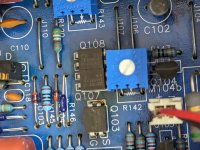
From what I've read in other threads, the IRFD210 LTP transistors could be suspect, in which case I'd have to source matched pairs. Is there something else I can try?
Thanks in advance
A few weeks ago I rescued a broken, neglected, and abused GFA-5300. I now have the amp working, but can't get the DC offset adjusted to spec, and am hoping for some help on next steps.
To get the amp to this point I did the following:
- remounted a dislodged transformer (the amp had been dropped)
- removed years of dust and crap
- changed caps (factory Lelons were bloated and leaking, with some hanging on by a single leg)
- scrubbed and reflowed boards (the drop caused some severely cracked joints)
- gently tightened transistor mounts
- new thermal grease on the thermostat and bias transistor
Plus some bonus stuff:
- changed trim pots to Bournes
- changed input cap to Panasonic polypropylene
- changed signal path resistors to metal film
- cleaned up wiring
- added IEC + earth loop breaker from Hoppes Brain
With those tasks complete, the following good things happen:
- amp powers on
- PS voltages are correct
- bias adjusts correctly
- plays music!
Unfortunately I can't get the DC offset adjusted correctly. I'm measuring with the amp warmed up, no load, and the inputs shorted. Instead of no more than +/-10mv (per the service manual), I'm getting 60mv on the right channel and 110mv on the left with the trim pots fully adjusted (DC values go higher if I turn the trim pots the other direction).
From what I've read in other threads, the IRFD210 LTP transistors could be suspect, in which case I'd have to source matched pairs. Is there something else I can try?
Thanks in advance
Attachments
For no cost, you could swap the input pairs between channels, and see if the lower offset follows the transistors.
They can degrade over time, and with hot swapping.
Or maybe C107/108 are leaky, if you haven't already replaced them.
They can degrade over time, and with hot swapping.
Or maybe C107/108 are leaky, if you haven't already replaced them.
Mosfet transistors do drift with respect to their Vgs. I would set the pots to their midpoint. Then measure Vgs of all 4 transistors. Then swap to get pairs that have the closest Vgs match. It just might get you there!
Or just live with it, while it's a bunch of offset, it's not enough to mess with your speakers or cause the amp to misbehave in other ways.
I see the parts are available in DIP package by DigiKey for 99 cents. Buy a bunch to match and use extension wires to retrofit if necessary.
Or just live with it, while it's a bunch of offset, it's not enough to mess with your speakers or cause the amp to misbehave in other ways.
I see the parts are available in DIP package by DigiKey for 99 cents. Buy a bunch to match and use extension wires to retrofit if necessary.
Measure voltage across R023 and R123. Any voltage present is leakage through the adjacent caps and will add offset error at the output, (multplied by R120/R121).
If you are able to set bias current, output FETs are not an issue.
If you are able to set bias current, output FETs are not an issue.
Thank you for the suggestions. Since the IRFD210 pairs are mounted end to end, I'm thinking I can install some 8 pin DIP sockets that I have on hand to make it easy to swap them out. I'll try rayma's suggestion to see if I can mix the pairs up to get a better match, and if not, order a few and try matching some new ones. I see that Q103 is also a IRFD210; is there any reason why I shouldn't socket it as well, then through it in the mix while I'm measuring the other two pairs?
Attachments
Yeah I suspect the input LTP mosfets. They really cook! Get yourself a DIP-16 heatsink and epoxy it across the tops of both. (JB Weld) That will dissipate the heat as well as keep them thermally tracking.
Matching mosfets is pretty easy, easier than bipolars. Nelson Pass has the method, you can build this on a breadboard.
https://www.passdiy.com/project/articles/matching-devices
Matching mosfets is pretty easy, easier than bipolars. Nelson Pass has the method, you can build this on a breadboard.
https://www.passdiy.com/project/articles/matching-devices
Thanks Phloodpants, I saw your suggestion about the heatsink in a another thread and added a couple to a mouser order yesterday. Papa's matching instructions are exactly what I'll need. Would you hazzard a guess as to how many IRFD210's I will need to order and sort through to get two nicely matched pairs?
It's been a while, but I seem to remember them being pretty tight. If you order 20 I think you can get within 3%.
I feel compelled to point out that you can make a few DC measurements in situ and get good insight to what's going on with the offset issue.
To review basics, remember to regard the PA as an opamp: if you have 0 offset error in the input pair and negligible voltage drops in the bias resistors, you're pretty much guaranteed to have 0 offset at the amplifier output. To restate the obvious, when you match input transistors, you're trying for 0 offset voltage error between the gates when the FETs have equal channel currents.
In this amp, you can measure the input voltage of Q007 at cathode of D003; ideally, it will be 0mV, especially given a shorted input. Similarly, measure feedback voltage of the gate of Q008 at the cathode of D004. The difference between these two measurements is the input voltage offset error. Now connect your meter between the cathodes of D003 and D004. If all is well, the offset error will be displayed directly on the meter. Now you should be able to assess input offset error as you adjust R042. Ideally, R042 should trim input offset to 0, but it may not. (Note that you can measure input tail current by measuring voltage across R030. Nominally half this current should flow through R006//R042.)
With input offset trimmed to 0, any amp output offset is likely due to leakage currents flowing through R020 (maybe via leakage through C007). At some point, you should also remove the input short and check for any leakage, revealed at D003 cathode.
Good luck!
Last edited:

Thank you for the excellent guidance BSST. I will get to work this week and report back once I've learned more.
- Home
- Amplifiers
- Solid State
- Adcom GFA-5300 repair and restoration: DC offset issue