Instruments Amp Y4 trio

938A8F85-84CC-4CC5-9BCE-0D9D6C742B48.jpeg


Hi all, trying to assemble a music system that a tri of year 4 primary schoolers may plug various instruments into for practice. This needs to double up as a bass amp for my daughter for her electric bass classes at school. She is used to the little sub plugged into our mixing desk at home and like me she hates the weak uninspiring sounds that the usual suspects in the music shop make in the sub $1500 mark. Our usual listening and playing stuff is West Indian including dub

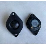
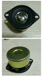
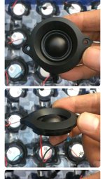
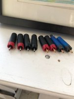
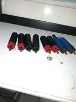
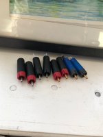
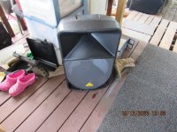
For $35 I found a group of four Logitech 2.1 systems that included the one that was the same z623 model sub we use. Issue was that this one didn’t have the satellites in lot. The left satellite contains the controls and plugs into a DB15. The right satellite plugs into a dedicated rca. Rear panel also has rca and 3.5mm inputs. The missing satellite has another 3.5mm input as well as headphone out, bass level knob, volume knob

In that lot there were satellites from LG as well ones for the other smaller three subs

I have a little USB/battery powered mixer with Bluetooth, instrument in and aux in

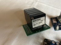
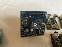
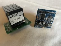
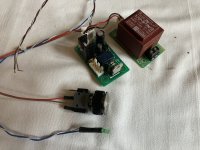
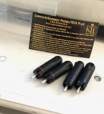
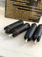
Also have two Kemo M040n black box preamps, 18 volts of battery, 18v dc wart, 9v dc wart, pots and passives for passive tone controls, passives to build four sets of the MPF102 jfet pres from another thread

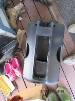
Add to the list some knobs, wheels, mdf, marine ply, upholstery fabric, carpet, retractable handle from bag

Hoping to fit the sub and a pair or two of satellites into another new box and something the gyals may plug things like electric bass, upright bass pickup, mic, electric guitar, electronic drum set, tablet and like. Basic controls to find basic sounds

First challenge is to decode the DB15 pinout. I know that the pins for discrete input for the sub section and standby from the net searches. Plugged into this pin with the little mixer and bass guitar sounds sweet but the loudness is absent. Swapping the satellites from the home system and plugging the mixer into that returns the loudness

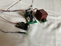
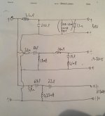
Now I am going to try to cascade (is this the right word, please advise) one Kemo into passive bass and treble tone circuit assembled from net schematics. That will be followed by another Kemo. Both Kemo will have 10k pots on the input lead. I’ll plug the bass into this and hook it to the sub direct pin and see if I can get acceptable volume and tone control

Hoping this works, then I’ll have the starting of a bass amp that my kid may find inspiring and satisfying to play

Next thing to attempt is finding the direct ins for main speakers amps in that DB15. For this I will need to make or buy a three instrument channel plus stereo mixer and 2.1 filter

As a side I have been curious about the MPF102 jfet. I have some and the parts needed to build some internet schematics. First attempt at building from random schematics as well as trying to learn about circuits like these pres ans mixers

Hope to find some assistance here if I get stuck. Thanks and regards

Randy

One DVC woofer with two full range drivers in stereo?

Hello all
I am thinking about making a sound bar type unit using three drivers only but still getting a stereo sound overall

I have a 10" driver with dual voice coils each 4R and a pair of 3" full range drivers that work happily when run in an active 2.1 setup. I would like to use these drivers with only a 2 channel amp and using a passive crossover on each voice coil of the woofer to run a full range

I have a two channel power amp board with a built-in mains power supply and has aux power outputs for preamps as well as fans. Insterested in making a custom tone control to control level matching between the drivers over using another amp to run them in 2.1

Most of the bass should come from the woofer so the passive crossover should be around 500hz

Is this kind of setup possible?

Opinions please 🙂

Precision Power PCX 4400 Amplifier; Powers Up but no sound

Hello,
I am new to this forum and apologize if I am in the wrong section.
I need help. As the title reads, I have a ppi amp that powers up, appears to be spotless inside, nothing looks burned or smells fried. I got it this way. I know it isn’t anything on my side because I swapped it for my other amp that is identical and works in that vehicle, this one just has no sound.
I am an HVAC Technician but this is beyond my skill.
Any easy fix would be awesome or if you know someone that could fix it for me, I wouldn’t mind paying. I prefer old school amps.
Thanks,
Scott Murphy

AP7311 - The mysterious IC

Recently i cam across the AP7311 is used in my 5.1 home theater system from true sound waltz. This is has inputs from aux/dvd etc and output goes to power amplifier. Clock and data lines going to sp3306 mcu. This AP7311 has 28 pins. This IC seems to be prologic decoder with audio analog input selection and digital volume controller. Can anybody help me in identifying this IC exactly what it is. Will be thankful if somebody share its datasheet as well.

rate my first 3 way crossover design

Hey guys!

I have finally gathered confidence to design my first own crossover from the little knowledge i gained. would you please help me maybe improve on the design or give me some suggestions. I have tried to crossover the speakers at 200 and 2000Hz.
These are the drivers that i am using!
Tweeter: https://www.soundimports.eu/de/monacor-dt-100.html
Mid Driver: https://www.soundimports.eu/de/scan-speak-18w-8545-01.html
Bass Driver: https://www.soundimports.eu/de/scan-speak-25w-8565-00.html

Thank you very much in advance. keep in mind that this is my first crossover.
Crossover 1.png

For Sale TKD 4CP2500 10K & VCU Muses volume controls. AMB E24 power switch

All items are in perfect condition and working order. Prices include postage to UK, overseas please enquire

TKD 4CP2500 Balanced 4 channel pot mounted on PCB, hardly used - SOLD

Academy Audio VCU MUSES all in one volume control, single ended very lightly used - SOLD

AMB E24 power switch driver kit, includes momentary power switch and power supply SOLD

Attachments

  • IMG_0380.JPG
    IMG_0380.JPG
    358.4 KB · Views: 136
  • IMG_0381.JPG
    IMG_0381.JPG
    354.2 KB · Views: 129
  • IMG_0382.JPG
    IMG_0382.JPG
    423.1 KB · Views: 129
  • IMG_0386.JPG
    IMG_0386.JPG
    618.5 KB · Views: 115
  • IMG_0387.JPG
    IMG_0387.JPG
    791.6 KB · Views: 132

The legendary K-Horn using altec 511B and 808-8a

(please move this thread to the new Horns forum when possible 🙂 )

It's a K-horn, which is short for Korner horn or Klipsch Horn depending on who you ask. The original was designed and produced by Paul Klipsch around 1946 and the rest, as they say, is history. https://www.klipsch.ca/blog/klipsch-down-low-horn-speakers

The design was licensed by the British company Vitavox and 20+years ago plans derived from the Vitavox version found their way to Ontario where various models were produced (and I know of an enthusiast who's still active and who helped build the boxes that now sit in my basement).

They are capable of good imaging so one need not be afraid of corner-situated speakers: https://www.diyaudio.com/community/threads/corner-horn-imaging-faq.248444/

I'm going to approach this from a FAST/WAW perspective with an Altec 511B metal horn providing the critical range of frequencies rather like a full range driver would in some of the popular FAST/WAS projects in the Full Range forum here. The driver on my 511B horn is the Altec 808-8a CD.

The box defines the woofer horn, so the only part left to play with will be the X-over and here there are many opinions.

FYI - I had originally turned down the opportunity to re-store these speakers after realizing it was boxes only with no drivers or metal horn and they are darn heavy but I was told that they sounded very good. Stereophile has this to say about the modern version "No one with a taste for realistic playback, and especially no one with a taste for low-power amps and high-sensitivity speakers, should miss a chance to hear these." https://www.stereophile.com/content/klipsch-klipschorn-ak6-loudspeaker

Attachments

  • 808a-cut away dwg.png
    808a-cut away dwg.png
    721.1 KB · Views: 1,162
  • Like
Reactions: JRKO

Audio Research D70 "POP!" on shutdown

Hello!
I've recently 'repaired' an ARC D70. It was victim to a catastrophic failure, with the filter caps shorted with signs of arcing, a bias cap bulging and a blown 6550 tube. After replacing all the electrolytic's, a couple tubes (and re-biasing, of course) and some burnt out resistors, it sounds amazing!
The only trouble is that it makes a short zappy 'hum' on startup while it warms up (faulty thermister perhaps?), and every time you turn it off, there is a loud thump/pop in the speakers. I would assume since this beast has very complex (at least for me) power supply design, that this might not be normal operation- especially the shut down pop.
I'm running an attenuator from my source to the inputs, so no preamp to blame.

Any suggestions?
Schematic attached.

Attachments

EL84 PP Output Transformer Recommendations?

I'm looking for recommendations for ouput transformers for an EL84 push-pull amplifier.

  • The schematic calls for 8k and I need 8 ohm output, with a 4 ohm output being nice to have but not strictly needed.
  • Solid bass performance required to 20Hz. Poor/lightweight bass performance is not acceptable.
  • Rated 15 watts (or more) I suppose.
  • Ultra-linear is not needed.
  • I cannot use toroidals. They need to be a traditional transformer with end bells and wire leads.
  • I do want a very good transformer, but I don't want to spend a million dollars on a pair either. I know there are some very expensive names out there.
I am looking for a solid performer that will not be light on the bass. A lot of transformers are available from China, but you never know what you are going to get, and most are only rated down to 30Hz which usually means closer to 50 or 60Hz in reality.

What high quality OPTs are currently available? Most links that I find no longer work or the product is no longer available.

Balance resistor ratings/size for tube PSU

Put simply, I have filtering caps run in series that need appropriate balance resistors. The set up is this:
  • Two sets of two 270uF, 420V(max) caps connected in parallel.
  • Those two sets are connected in series
  • In effect, I have 270uF rated for 840V
  • Using the following formula:
    ratedR.png
  • and with the values:
    • n = 2
    • Vrated = 420V
    • Vbus = 497V
    • Imax_D_leak = 3 x sqrt(270uF x 420V) = ~0.001A (assumes no leakage in one set and maximum leakage in the other)
  • I get an Rbalance of 343K
Here's the thing, I see a lot of schematics that have somewhat similar configs. They typically use either 100K or 220K ohm resistors (Merlin's PSU book recommends 50/C, which gives a conservative 95K). Few give ratings, and they range from 1/4W all the way up to 5W.

IMHO, the nearest common value for optimal balance resistors would be 1/2W, 330K ohm. Unless I calculated wrong, or am missing something?

Budget car tweeter high pass

I have read information for some time now, including topics on this forum. But I haven't found an answer yet. I want to use a set of 4 ohm tweeters in my car, high passing at 3500hz with at least 12db. I have looked at a Linkwitz Reilly crossover design and I got values of 5,69uF and 0,36mH. Here's the thing though. It's a budget build and the inductors I have found and are not said to be of mediocre quality (vented core copper for example) cost a lot of money. If need be for good quality sound then I will pay the money. But I was wondering if anyone has any knowledge how I could do this cheaper without much quality loss? I'm hoping not having to spend 30 to 40 dollars on a set of 2nd order high pass filters.

My curved 180 degree tweeter second try :)

Trying something different, trying to figure out if this sort of thing is useful to make.. or ditch the whole idea. might try some things before i ditch it completely. i am thinking of making a higher one and using 2 coils for mid and 1 that reaches to 18khz.... making vertical dispersion as good as this one... maybe... interesting. while having much more surface area for mids !

here is a small video Login to view embedded media

Telefunken M15 and M15A Handbook, Operations and Service Manuals in English

Hello everyone!
I'm looking for the English versions of the Telefunken M15 and M15A Handbook, Operations and Service Manuals.
Actually, I'm looking for any documentation for the Telefunken M15 and M15A in English, even brochures.

I have a Telefunken M15A in working condition that needs to be serviced and calibrated. I have scanned PDFs of the Handbooks and some other documents in German but it's very difficult to translate and understand what you're supposed to do, especially because the manuals are not as straight-forward as Studer manuals.

@tmuikku I read a post on the groupdiy forum that you have these manuals scanned and asked that anyone else that needed the manuals should reach out to you on diyaudio. If you still have the manuals and don't mind sharing them, can you please send them to me?
I'm, posting this publicly so that other people can find this info more easily. Ultimately, if you don't mind, I would like to publish all documents and manuals somewhere where they will always remain publicly available for everyone, possibly on GitHub in a public repository.

I believe that one of the reasons why Studer machines are more popular than Telefukens is the better written and easily publically available documantation about them. Also, my current impression is that the Studer groups and forums have more people that want to help eachother out. I would like to change that and find a way to help other people with Telefunken machines.

Yamaha CR-820 receiver issue

Hey DIYers',

I've got a CR-820 which has a problem upon cold start-up - after the protection relay engages, the first 5 seconds of using the volume knob produces loud static noises. I need to wait a while to reproduce the issue, hence cold start-up only.

I have a feeling it's a capacitor - DC voltage on the pot would explain the noise, cap charge and discharge time would explain why the problem fades and then doesn't return until the amp is cold again.

Am I on the right track? Any tips on where to starting looking would be appreciated!

http://akdatabase.org/AKview/albums/userpics/10007/Yamaha CR-820 Service Manual.pdf

Is it feasible? A Turntable that instantly converts analog to digital with error correction for wow and flutter.

Background

With a halfway decent sound system, I started looking for new music to listen to. "New" meaning music I have no heard before, and that would mean a trip to the 1970s over again, where the music I like originated. As part of my journey, I came across, or to be more accurate, searched for and found Bostons song and "More Than A Feeling" and their also album "Third Stage" on my streaming provider. Interest in the band led me to watching an interview with Tom Sholz, who basically founded the band, and created that guitar sound that we all know and love. He said something intriguing: that he could never get the CD recordings to sound as he wanted them to sound.

https://www.diyaudio.com/community/...l-insights-as-a-producer.398525/#post-7331773

He said he found it difficult to mix for the CD format, and he was able to come up with a final recording that 'did not annoy him too much' as I recall he said.

If there really a problem with the CD format, then I should think of buying some other format. Maybe vinyl. Vinyl had that clarity, but it never impressed me with its bass output. The cassette tapes I have are now beyond restoration, at least to the level of quality I can now hear on the mp3s and CD recordings.Playing a CD or two, I could hear a somewhat metallic ring to the sound (I am able to detect the difference between some Digital amplifiers and Analog amplifiers over You Tube, so the effect is real)

Listening to the dreaded Crosley turntable reviews over YouTube again, I was able to hear a clarity that was pleasing: I knew of course better turntables connected to better systems would sound much better, and I was intrigued. I have ordered my first turntable and a record to test it with as well, it is, shall we say, a turntable that is not really recommended by anyone here. Think Crosley and you are not far from the truth. My journey has begun, it seems, hopefully not a false step.

From watching reviews of the lowest end of the turntable market (There was one reviewer who purchased a turntable for $10, it sounded ok but let's leave it at that), I was directed by YouTube to the very highest end of the market, it seems, the OMA turntable:

Login to view embedded media
I was listening to an incredible story. From the thousands of hours of research, to the cast iron casing, only 1 in 10 is acceptable, a powerful direct drive motor, and a dedicated motor controller, I could not believe the amount of money and effort that had gone into this design.

Was there a better way?

A Possible Solution

The main problem that seem to plague the turntable are variations in speed of the turntable and vibrations. You can add surface noise to that as well.
One approach is to maintain the speed of the turntable no matter what. The other is to try to correct for these variations. Immediately there is a problem, as OMA has pointed out, the variation in speed changes the character of the music itself.

Is it possible, and I know it is possible, I should ask how successful is it to use a method used with CD players and digital music, to convert the signal into digital format, and then store this signal in blocks of data for processing and correction, and then output that data to the amplifier at exactly the correct speed? The corrections will have to incorporate the following.

1. Corrections for wow and flutter using a turntable speed sensor as input
2. Corrections for surface noise from a 'surface noise library' that matches the surface noise pattern

Apparently there are some related patents:

https://patents.google.com/patent/US3983316

https://patents.google.com/patent/US3873764

Has this ever been attempted? If not, anyone on this forum may develop this further, I only ask that the idea be acknowledged, that it came from me in this post.

Sony CDP 228 does not recognize CD

Hello all,

I have a Sony CDP 228 ESD with a problem in the CD reader.
Was bought en ebay a month ago and worked well while.Now CD is not recognized.
The loader tray works well, but the disc does not rotate, the laser head moves several times trying to focus, but the disc only rotates a quarter of a turn or less, and it goes like at intervals
I had read about pickup laser KSS151A,check corrient laser.
I have been able to measure the current of the laser while it tries to focus the disk for several seconds,then goes off. Its current is 54.06 mA, (the laser sticker indicates 51.3 mA)
Based on this, the laser appears to be within its life span (less than 10 mA increase)


But the first question that arises in my mind.
Could it be the CD spinning motor or could it be the laser ? How to rule out spining motor or laser head to begin?

Thanks in advance and regards

Yamaha NS1000 crossover Tweaks

This thread is started as a continuation of a previous one regarding the effects demonstrated by changing the capacitors in the yamaha 1000's crossover.

I have now very crudely removed the crossovers and made them external and I have changed every capacitor with modern day non-electrolytics ensuring exact capacitance is copied.

The results were stunning! Now I thought the Yams were superb speakers with the speed and transparency of my stacked quads. However! With the above changes this is what I get with minimal burn in time mind! The volume output goes up significantly ???about 30% for the same volume position.

Increased detail and air around the musicians. For example in terms of detail, well known studio tracks now clearly demonstrate stunningly the background studio noises. In term of music,cymbals have more shimmer and decay. The complex harmonies that make up a piano note are more audibly felt. Voices gain body and tonal WARMTH. The midrange becomes less recessed and far more prominent. The realism is in fact enhanced further than before, and trust me in stock state the Yams are one of the best i have come across.
Bass is clearer deeper and more detailed.

Separation of complex multi instrument tracks are suddenly clearer and more easily followed.

During the conversions I initially did only one speaker first. I was then able to compare a mono track between the tweaked and stock speakers. It was IMMEDIATELY apparent by jumping from one speaker to the other that the tweaked version was clearer warmer and had noticeably deeper bass.

Now I can only conclude one of three things

1) the original caps may have been knackered
2)externalising the crossover takes away those magnetic and sound pressure fields that may affect them
3)the original caps were of a crap quality.

Then what if I built silver inductors? or changed the caps to ultra expensive audionote copper? Or upgraded the internal cabling to one of the well respected manufacturers e.g audio note ansp??

Exciting or what.

My previous speaker experiences in chronological order are
quad esl57 stacked
spendor bc1
avantgarde duo
audio physic avanti
harbeth 30 and 40
rogers ls3.5a
etc etc

the speakers are being used with the following set up

pink triangle dacapo and transport
jadis jps2 pre
audio note 300b silver signature monoblocks
audio note silver cabling throughout

Which tweeter are good

My old tweeter were 2 inch 4ohms Kenwood

I am replacing them with new one I have sorted some tweeter can someone suggest which is should I go with.

Attached pics below.

Thanks

Attachments

  • Screenshot_20231216_103647_com.ebay.mobile_edit_3297282589599.jpg
    Screenshot_20231216_103647_com.ebay.mobile_edit_3297282589599.jpg
    169.6 KB · Views: 114
  • Screenshot_20231216_103728_com.ebay.mobile_edit_3290914501579.jpg
    Screenshot_20231216_103728_com.ebay.mobile_edit_3290914501579.jpg
    286.8 KB · Views: 106
  • Screenshot_20231216_103857_com.ebay.mobile_edit_3282418119289.jpg
    Screenshot_20231216_103857_com.ebay.mobile_edit_3282418119289.jpg
    298.2 KB · Views: 110

Full Range Speaker Size in Open Baffle

Most full range speakers are 8 in and larger. I'm planning to build an open baffle speaker with an included woofer. I'd like to use the Visaton B100 4 inch as the full range speaker. I was looking at the Visaton B200 8 inch first and noticed how much better the polar dispersion is in the B100. It seems to me that a four inch speaker would be faster and better localization too; but at a reduced volume.
Why not?
I'm planning to crossover to the woofer at 100-200 Hz to relieve the 4 inch of bass duty. Shouldn't that get me to a 90db output level? I don't need a lot of volume preferring smaller ensemble music -- and I have a JBL horn system in another room.
So right now I'm planning to build the Visaton No Box speaker about 25% smaller in height and width but not depth. I think I'd also offset the 4" somewhat to the outer edges of the pair. I'd use an electronic crossover and separate class D amplification for the woofers- Eminence Alpha 12a's.
Am I missing anything here???
Thanks for any help

noboxbb.jpg
noboxdimension.gif

Two pairs of Lat-FETs to play with

I was recently inspired by a thread here with a NAD lat-fet conversion, and did some reading on lat-fets/amps, and now I bought two pairs of Exicon ECX10N/P20 lateral fet's to play with, and the idea right now is to put them in a Pioneer amp I have on the shelf:
1701279210074.png


Thoughts/comments? Any reason this amp is not a good candidate?
Plan is to remove emitter resistors, add larger heat sinks, possibly rework bias spreader, and compensation could be a challenge..

Musical Fidelity A300 coupling capacitors

I've been bypassing the inferior sounding pre-amp section of this integrated by utilizing the pre out jacks as a power amp input. The DAC I have connected has it's volume controlled line out capacitively coupled, so I removed the bipolar cap C55 from the pre and jumpered across C3 at the power amp input. The sound quality improved in all areas aside from a quite noticeable low frequency attenuation from about 80hz down.

Space limitations prevent polypropylene caps from being installed, and I've read that PET or MUSE bipolar caps would offer little sonic improvement over the stock electrolytics. Any insight as to what might be causing this? There is no DC potential on the input.
Preamp.PNG
Power Amp.PNG

I ***** up

For starters I have an Audiopipe APDLO-16001D which is a dealer line series amp that can only be bought at brick and mortar stores of which there are only 3 of on the east Coast two in Florida and one in Connecticut. I live in NC right in the middle of them. I got lucky and bought it new in box from a guy local to me for $80 (so cheap I felt bad and tried to offer him $100 😂) as of right now replacing it is out of the question (with any amp at the moment for cost reasons) because of cost and distance, I am handy with electrical circuits and soldering so I would like to attempt to repair it myself with either new parts or parts salvageable from other amplifiers/electronics. So burnt up 3 of what Im pretty sure are mossfets, and one of the capacitors, that I can visibly see atleast. I called Audiopipe tech support and found out that it was likely from connecting the subwoofer with the amp already powered up. Something I had never had an issue with before or heard of. But I guess there's always something to learn. Also a few weeks back I could hear something loose inside the amp when I was moving it to its new location when I removed the cover it was a white ceramic box that was supposed to be attached to a post on the board labeled RX1 it had the same one opposite side of the board labeled RX2 still attached and the amp had been and was still playing fine with it disconnected so I removed it, put the cover back on and continued playing the amp with no problems until yesterday when I made the mistake that ended the amp. He told me I could email tech support for a schematic (not knowing what I'm looking at is 90% of the problem at hand, parts availability and money is the other 10%). So a schematic(if anyone happens to have one as Audiopipe has not yet replied) and parts list, potential electronics to find usable parts in and a second set of eyes that know what they are looking at and any other parts that may have damage that can't be seen along with any suggestions as far as what setting as far as volts/ohms/amps etc. and where/what to test with my multimeter for further diagnosis, would be super helpful. Attached are photos of what damage is visible along with an old Memphis 16-ST1000D that I could get some resistors and other common parts from if possible/needed.

TIA

Attachments

  • 17019001880145391061629270623677.jpg
    17019001880145391061629270623677.jpg
    313.8 KB · Views: 233
  • IMG_20231206_165458541_HDR.jpg
    IMG_20231206_165458541_HDR.jpg
    293.2 KB · Views: 248
  • IMG_20231206_165527388_HDR.jpg
    IMG_20231206_165527388_HDR.jpg
    281.1 KB · Views: 245
  • IMG_20231206_165517492_HDR.jpg
    IMG_20231206_165517492_HDR.jpg
    294.3 KB · Views: 244
  • IMG_20231206_165547355_HDR.jpg
    IMG_20231206_165547355_HDR.jpg
    282 KB · Views: 230
  • IMG_20231206_165553372_HDR.jpg
    IMG_20231206_165553372_HDR.jpg
    301.3 KB · Views: 237

For Sale or TRADE Two different Mofo Monoblocks and a Pass Front End

I did some experimenting with the 19V Mofo versions of these amps and enjoyed them for the last 6 months. I saved some boards to try out some 24V versions in the future but need to sell these to fund other projects. I also have a Pass Front end to sell with one of the Mofo pairs.

- First amp is mono blocks in a single chassis with Wima caps, matte silver painted faceplate, Peruvian walnut bottom, and heatsinks cut to size and mounted together. 19V Dell Power supplies included. I used Hammond 193T chokes. - SOLD!

- Second is a pair built on separate Peruvian Walnut Wood planks. Only difference are the boards, the heatsinks are a tad bigger and run a few degrees cooler, and the caps are Solen. Asking $250 and help to ship

- The Front End I built into a Hammond chassis. It has an Alps Blue RK27 10k pot, silver Mil spec wire, Mark Johnson's SMPS filter, Nichicon BP caps on the input and Wima caps on the output. Powering it is a 48V Meanwell SMPS and it is set at 20db to run the Mofos - SOLD!

I am also open to trades for DIYAudio parts, boards, kits, etc to experiment with.
  • Like
Reactions: 6L6

For Sale NIB Eichman KLE Copper Harmony RCA plugs+ 8 used Bullet Plugs

Sold sold sold….Here's four brand new KLE (Eichmann) Copper Harmony Phono/RCA plugs

Plus 8 of the older style Bullet plugs made by Eichmann. Two of the bullet are missing the little set screws. (See Photos.)

Free CONUS (continental United States) shipping. No international shipping. Not even Canada. Too much hassle.

$40.

I can take a Zelle payment or a personal check. Sorry, but I no longer take paypal.

Please know that I've been selling audio stuff online for ~20 years under the username Kolledog with perfect, 100%-positive feedback on all the sites. Never ripped off anyone. Have sold a few things on this site too.

Happy, merry.

Thanks.

Attachments

  • IMG_6191.jpeg
    IMG_6191.jpeg
    427.7 KB · Views: 105
  • IMG_6192.jpeg
    IMG_6192.jpeg
    367.4 KB · Views: 92
  • IMG_6184.jpeg
    IMG_6184.jpeg
    247.7 KB · Views: 88
  • IMG_6185.jpeg
    IMG_6185.jpeg
    255.5 KB · Views: 89
  • IMG_6186.jpeg
    IMG_6186.jpeg
    258.2 KB · Views: 86
  • IMG_6187.jpeg
    IMG_6187.jpeg
    219.2 KB · Views: 100
  • IMG_6188.jpeg
    IMG_6188.jpeg
    235 KB · Views: 81
  • IMG_6189.jpeg
    IMG_6189.jpeg
    292 KB · Views: 81
  • IMG_6190.jpeg
    IMG_6190.jpeg
    208.5 KB · Views: 88

3 way crossover with active crossing for bass / sub

Hi, I have used full analoge crossover for my 3 way floor standing speaker, vented not ported ( SP6600, Seas Excel W18EX and Seas Excel W26 ).

In the lately I have crossed between bass and mid / high with a Accuphase 2 way active fiter ( filter for mid / top is analog ).

Now I thinking of using only a 1 way active lowpass filter for the bass, and use the hole pasive for mid crossing down. And mid / top is as now.
Maybe I tell it complicated ( :
I have picture of the hole passive filter, all the bass parts goes away when using 1 way filter for bass. But I have to put back the 68uF serie cap and the 1.8mH paralel inductor ( did not use them when crossing with Accuphase ). The reason for doing this is that we ( friend and me ) have listen to some speakers and hear that the mid / top is gaining (play more freely and more detail / airy top from have passive crossover, compare to semiconductors ( opamp ).

1: Crossed at 200Hz before, testing 110Hz ( between 6.5" and 10" ), some advice here, pros / cons for where to cross?
2: The two parts that I have to put back (68uF and 1.8mH, have to change the value when change crossoverpoint ). What is that filter called, CL filter ?
3: Could I used a RC filter insted to cross the mid from low Hz, or maybe the cap and inductor is there for a special reason? I know the parts filtering upwards, the 1.8mH serie inductor is for rolloff uppwards and the paralell 10uF cap and 0.1mH inductor is a surge circut to take hand of the around 7000Hz breakup from the Excel 6.5" cone.

Puhhh!! Hope you understand the questions.

Frank

Attachments

  • IMG_0901.jpg
    IMG_0901.jpg
    243.8 KB · Views: 177
  • IMG_2079.jpg
    IMG_2079.jpg
    594.6 KB · Views: 162

Rockola PA AMP

Hello folks,
here is a re-design of pcb of Rockola PA amp.
let me know your comments.. let me also know replacements of trannies.

I have tried to make it more convenient to build.
I am posting input circuit... output stage is coming up...
I will try to link the design, here or next post..
regards
prasi

Attachments

  • ROCKOLA PA AMP.png
    ROCKOLA PA AMP.png
    251.3 KB · Views: 1,749
  • ROCKOLA PA AMP-SCH.png
    ROCKOLA PA AMP-SCH.png
    57 KB · Views: 1,295
  • amp_expandible.pdf
    amp_expandible.pdf
    1 MB · Views: 505

E-choke performance testing

I’ve recently been testing a basic e-choke for its frequency attenuation performance, as that aspect is somewhat lacking from what I can identify on-line. Testing has allowed a better insight into part selection and also general e-choke operation.

The test jig and e-choke circuit I used is attached below. A two channel PicoScope 4224A and FRA4 gain-phase software are used to measure the e-choke attenuation from ‘input’ to ‘output’, with a simple 1 ohm resistor load. The waveform generator output of the Picoscope is buffered/boosted by the venerable LM12 power opamp, which achieves a flat large-signal amplitude out to 100kHz, and -20dB out at 400kHz. The signal generator and FRA4 software allows a dc voltage offset to be included with the ac signal, which can then apply a practical DC voltage across the e-choke DUT, along with substantial AC voltage to allow gain-phase measurement across the e-choke, given that e-choke applications for say valve amps require an e-choke providing circa 100mAdc. The e-choke dc current is normally determined by the application amp's operation, but for the purposes of this test the e-choke dc current is set by applying a dc voltage from the buffer to the input of the e-choke.

The low frequency operation of an e-choke is explained in a few on-line references. In summary, the resistor divider R1:R2 sets the idle Vds voltage of the fet for a given e-choke dc current. This is done by applying a Vgs-on voltage consistent with the dc voltage drop across R3 and the specific Vgs-on characteristic of the FET used. For example, with an input voltage of 10Vdc, and Idc=100mA through R3=20 ohm, the Vgs-on=3V as R1:R2 sets Vgs-on + Idc.20 = 5V. In a class A amp application with a constant current draw, the idle voltage drop across the e-choke will vary somewhat as the FET Vgs-on voltage characteristic is temperature dependent, but would otherwise be constant.

An input ripple voltage causes Vds to vary similarly by way of C1 keeping Vgs pseudo-constant with a characteristic that emulates an inductance (effective impedance of the e-choke increases with frequency by way of C1 impedance falling with frequency). Vds negative swing is limited when Vds approaches FET on-voltage (~0V), so a symmetrical swing of Vds is about twice the idle Vds voltage – which then relates to the maximum incoming ripple voltage that the e-choke can linearly attenuate.

With respect to frequency response of attenuation, the impedance of C1 approaches zero above ball-park 1kHz, and so gain (attenuation rate) then changes from -20dB/decade back to unity. Above nominal 1kHz the effective capacitance across the FET (drain-source) starts to become significant such that FET impedance becomes capacitive and dominant, and the e-choke gain increases at +20dB/decade back towards unity. This frequency response is equivalent to that of a common iron-cored choke where choke impedance rises with frequency but then reaches a peak at the choke self-resonance frequency, and then falls as the shunt capacitance of the choke winding then dominates.

Of interest with the test measurements was the influence of FET capacitance. With an IRF840, the maximum e-choke attenuation reaches about -90dB at 1kHz before the impact of FET capacitance then starts to dominate, and at higher frequency represents a drain-source capacitance of about 2.9nF. The IRF840 has a datasheet Coss of about 2nF at Vds=1V, so it seems like the FET gate resistor and/or a Miller effect may be at play.

Changing to a MTD1N80 FET, with a significantly lower datasheet Coss of 320pF at 1V, did push out the frequency to above 10kHz where e-choke attenuation starts to fall, and the response represents a drain-source capacitance of about 510pF. Increasing R4 certainly showed a dominating influence.

This is all food for thought perhaps, although I don't think many have used e-chokes, and fewer have likely checked their performance.

Ciao, Tim
PS. excuse the error in LM12 gain, and the phase axis numbering in the middle plot.

Attachments

  • E-choke test schematic.GIF
    E-choke test schematic.GIF
    19.6 KB · Views: 228
  • Choke 2u2 11Vdc 85mAdc 2.5Vac 1R.png
    Choke 2u2 11Vdc 85mAdc 2.5Vac 1R.png
    22.2 KB · Views: 189
  • Choke 2u2 11Vdc 50mAdc 2Vac 2ndFet.png
    Choke 2u2 11Vdc 50mAdc 2Vac 2ndFet.png
    17.9 KB · Views: 190

Looking to replace the volume control on my tube preaml

Hello all. I'm not a builder so apologies for only asking for help.

I want to replace the volume control on my lab12 Pre1. I'm doing this because
a) I can't find a preamp I like better (I've tried a variety of integrated in the $20k range and I always come back to my lab12) and so I want to hot rod this one as far as I can and;
b) I need balance control due to hearing issues, the volume control doesn't seem to land in my favorite listening volume when using the remote.

So I'm looking for top tier sound quality, balanced, with remote, and ideally an digital screen so I can see the volume, but that's least important.

I would say cost is no object but understandably I would rather keep it under $1000.

I do not know how to tell if one is technically compatible.

I won't be doing the work of installing myself.

I don't mind hacking up the case or building a separate one. That side of things I'm good at.

Thanks so much to anyone who can provide suggestions.

A question about Sonus Faber Grand Piano Domus speakers

I own a pair of Sonus Faber Grand Piano Domus speakers and have a question: knowing that the two bass woofers in each speaker work in parallel, does the crossover send exactly the same frequency range for the two woofers or they work with different frequency ranges?

In the second case, what's the frequency range sent to the first/up woofer?

Thanks in advance.

The Fever Bile eBay 6J1 preamp everyone loves (Smart people pls help!)

Im trying to get a little 6j1 tube preamp (the fever/bile one, lol) i built from an ebay kit to sound right through an (I think) 22k ohm input impedance (generic class D, tpa3255). The output impedance of the tube preamp is 5k ohm =/- so far as i can determine with research. It has rising output impedance toward the low end of the frequency spectrum but quite low near the high end. And as far as im aware, the rule of thumb goes, it wants to see no less then 50k input.

My obviously wrong logic (as well as several youtube videos and forum guides) would dictate i should be experiencing very rolled of low-end running it into an impedance that's too low. And i can fix that by changing the included coupling capacitors from 1uf 50v ceramic to 1-2uf 50v film caps.

Well when i plug the preamp into the power amp, the opposite is my problem, all i get is low end. Id guess its rolling the high end off no higher then 5khz. Went ahead and did the coupling capacitor mod anyway, and as the problem would dictate, it made the issue got worse. At that point i assumed there was some components functioning improperly so i ordered the kit again, exact same issue.

For the hell of it i plugged the preamp out of my little kit tube headphone amplifier into the power amp. Exact same issue, but plugging in the headphone output sounds great. I do not have this issue with my DAC, my tube phono preamp, or any other line level source of audio i have.

To add to the confusion, they all sound just fine plugged into the 3.5mm aux input on the back of the phono preamp (Fosi x4), but fosi is not being cooperative on telling me what the input impedance of the preamp when used as a buffer only so i can actually understand anything i'm observing, i don't have enough info on my own. very much a beginner, and for whatever reason google has been all but neutered. Obviously it's going to be very high, it's a buffer. But no clue the actual value.

What am i missing? I'm definitely missing something obvious here, i've been searching off and on all day and cant figure out how to fix my issue. Should i drop the value of the coupling capacitors and see how that sounds? Im just learning as far as this circuitry goes and i dont want to damage anything.

Schematic of the amp in picture. And i am aware of the output resistor to ground error in it as well. I was able to remove the hum with a modification to the filter cap circuits, and into my fosi buffer and the yamaha s801 in the den, it sound phenomenal. So i'm pretty motivated to get the thing right for my bedroom/desktop power amp. The fosi x4 handles tubey imaging duties in the den just fine already.

download.png

TPA 3110 Connection Help

Hello I have a question how to connect to the tpa 3110 xh-a232 amplifier using the bluetooth module, I already have this module connected, I mean how to connect the 12 volt battery to this design, with a connector for charging and how to make the current from the battery flow to the bluetooth module and also to the amplifier. Will I need an overcharge protection module or something else? A diagram of how to handle it all would be enough for me.

1702756680545.png
the amplifier I'm writing about
1702756773061.png
Bluetooth module I'm writing about

QUAD ESL-988 popping

After over 12 years of perfect service, one speaker suddenly began popping loudly with approx 0,5 s intervals, sometimes a little faster or slower, sometimes buzzing, too.
The pop sounds a a bit like a relay klicking, too, but there isn't any relays in there afaik. It is likely the lower bass panel.
Anyway, I try to avoid opening them. If there any chance by letting the pop on for until whatever has crept in between the diaphragms burn out? I have put them on the side to hope smth moves in there and also hit them gently. No change.

Adding optical input to Weilang DAC7

Hi.
I have a Weilang Dac7 with USB and coaxial input. It only has a "dummy" optical connector. It seems like it was an optional feature and I did not explicitely ask for it when I bought it 10 years ago. Or maybe they "forgot" to set it up? 😀
I guess this is not an easy task but in case it was not so, could I wire the connector to make it work? It has a WM8805 spdif transceiver and I was reading this is then doable.
I gather I need the proper voltages from the PCB and I see there are +/- 3.3V. Where should I get the signal from? It already has got a switch to choose between USB and spdif input.
I think I found the schematics on the web but I do not know whether it is allowed uploading it here.
Thank you!

For Sale Iron Pre SE - Fully assembled board (with optional transformer)

SOLD

Hello,

I had the opportunity to build both Iron Pre SE and BAL. I have put my BAL to work and decided to sell the Iron Pre SE.

For sale is the fully assembled and tested PCB, ALPS potentiometer, and twister input selection board, optionally the power transformer with cover.

Asking $220 for the board and $30 for the transformer with the cover + shipping (Flat rate USPS priority). Prefer selling with the US due to the shipping costs, etc.

Regards,
Subbu

Denon POA-2800 Protection Mode

Hi All (First Thread). I am not very fluent with electronics but I am hoping for some guidance troubleshooting my amplifier. It was working before I opened it up to replace an RCA input jack. I did that and blew out considerable dust with compressed air. Now it stays in protection mode. I have a multimeter and downloaded the PDF for the amp. Where should I start?

QUAD ESL-63 panel that rattles

I'm reaching out to anyone on this forum that has Quad ESL-63's that might be located within a couple of hours to me in Hagerstown, Md. I recently discovered a rattling or buzzing sound coming from one of the panels. At first I only noticed the rattle on bass notes (stand up bass or synthesizer) but now it seems to be constant on any music played. The other panel has no issues whatsoever. I contacted Kent at Electrostatic Solutions, he said using a heat gun might solve the problem. I'm no expert with a heat gun, have any of you 63 owners had a similar issue as far as the buzzing or rattling? Has anyone here used the heatgun and if yes could I bring the panel to you to do the repair? I really don't want to experiment and possibly do damage to the panel. I checked Fedex shipping rates and it is almost $400 one way. I'm trying to avoid sending all the way to Kansas City. Any help would be greatly appreciated.

Thanks Blair

The Edgar Show Horn

Hi All,

I am after some advice on suitable replacement drivers for this particular bass horn. Edgar used a ECM 12 L unit which, as far as I am aware, has been discontinued.

The specs can be found in the PDF in the Articles section here:

Download Section

Fs-55
VAS (Cu. Ft)-3.3
QES-0.25
EFF (db)-98
ST (Sq. in.)-36
FHM-440

Edgar also explains why this particular driver seemed to suit the Show horn well.

I am intrigued by this driver-

AE Speakers --- Superb Quality, Unforgettable Performance, Definitely.

Any thoughts on the aespeakers, Lambada 12" offering for this application also most welcome.

Just wondering if anyone else has any experience on this particular design and maybe able to offer advice on the matter, maybe something from B&C has been successfully implemented?

Best wishes,

Simon.

DAC noisy (McIntosh)

Hi all,

I have a mcintosh caraudio dac
Its a bit noisy when playing music. Its a strange noise that seems to play along with the music.

So far i've opened the unit checked the supply voltage and checked the pin lay-out of the dac chip which are 2 times Burr Brown pcm1704. I have checked the supply voltage on the Pins but cannot seem to find the issue.

Im not a full blown electician, i just know a bit of the basics.

Anybody that can help out here?

Attachments

  • 20231028_144521.jpg
    20231028_144521.jpg
    436.8 KB · Views: 110

Memphis Belle 16-ST1300D

Hello,

Any schematics for this amplifier?

Amp produces rail +/- 50 Vdc (current limited bench power supply).

~800 mVdc across all speaker terminals.

Relay clicks, output, albeit noisey, on the class D sub channel.

No output on any of the 4 class A/B channels.

The only thing visible I can find is a burnt resistor R797 that I cannot make out the bands, but it reads 31k in circuit, (see pic).

One leg R797 goes to C726 0.1 uF ceramic disk capacitor that goes to ground.

The other leg R797 goes to C728 0.1 uF that goes to ground. The other way off the same leg of R797 terminates on the top layer of the board and I assuming goes somewhere else, although I have not been able to find what other component it connects to.

Attachments

  • Input.jpg
    Input.jpg
    753 KB · Views: 143
  • Middle.jpg
    Middle.jpg
    696.5 KB · Views: 117
  • Power Supply.jpg
    Power Supply.jpg
    772.8 KB · Views: 139
  • R797.jpg
    R797.jpg
    400.2 KB · Views: 129

"Over the Top" SINGLE 2-way loudspeaker Prototype with $1,250 in Deluxe parts

Use as a Center Channel, Cannibalize for Parts, or Build Another!

This SINGLE prototype has served its purpose, and is ready to relocate to a new home. Here's the parts list:

Eton Fountek Ptype Costs.png


Here's a YT (FWIW & YMMV): Login to view embedded media
The front panel is Richlite Birch Plywood Stratum. The light-colored "Edge Protection" wood fillets at the longitudinal corners of the cabinet shell are Extreme Tiger Flame Maple Luthier-Quality highly figured wood that costs about $100 the board foot. The shell itself is .75 MDF. The Precision Flared Port is stuffed with cocktail stirrer straws. The prototype will be shipped in a sturdy soft-sided beverage cooler inside a cardboard box. That beverage cooler cost about $30 and I will throw it in at no charge. BTW, the original Fountek tweeter got beaten up a bit, so I swapped it out for one that had no hours on it. I can provide the crossover schematic and parts list, and contact information for Corwin, if you want to build another to have a pair. BTW, the crossover is asymmetrical, 2nd-order Linkwitz-Riley crossing over to 3rd-order Butterworth @3kHz. Because of that, the tweeter has to be wired up in opposite phase: crossover tweeter leg positive wire to ribbon tweeter negative terminal--that is not a mistake.

I think that $250 plus actual cost of shipping is a fair price, but I will entertain reasonable offers. PLEASE realize that there is only one loudspeaker being offered because I make prototypes one at a time. I am letting this one go because I am a lot happier with the Beyma TPL-75 AMT tweeter and the Purifi 5.25 woofer, with passive radiators. I am hoping we can move the crossover point down to 1800Hz... .

Thanks for reading,

john

Edit Dec. 21: Asking price lowered to $250.

Attachments

  • J Marks Eton Fountek Build.JPG
    J Marks Eton Fountek Build.JPG
    538.4 KB · Views: 80
  • IMG_9073.JPG
    IMG_9073.JPG
    345.7 KB · Views: 70
  • IMG_0061.JPG
    IMG_0061.JPG
    654.7 KB · Views: 82

New project: Bliesma T34B in WG, 18WE, 32W

Just to share very nice results of T34B plus 7" custom waveguide combination. Today I measured horizontal responses 0-90deg. I could not wish better results. Measurement was done in 2way cabinet with rounded edges to smooth out the responses as much as possible, mic distance 70cm, and gatting 4ms. My mic is calibrated to 25kHz.
This combo is planned for large 3way project with 18WE as midrange and 32W/4878T00 in sealed cabinet. Fully active, alldriven by OctoDAC with implemented miniSharc and 3 stereo power amps BV PA300SSE.

Attachments

  • 20210109_151211.jpg
    20210109_151211.jpg
    209.9 KB · Views: 3,587
  • 20210109_151220.jpg
    20210109_151220.jpg
    145.7 KB · Views: 3,212
  • T34B H 0-90.png
    T34B H 0-90.png
    117.6 KB · Views: 2,858
  • RB model.png
    RB model.png
    212.6 KB · Views: 2,892
  • Like
Reactions: stoneeh

Eimac 100TH SE

few months ago i was to ETF european triode festival in France
VinylSavor: ETF 2018 in France
and the shootout was win by Gilles we discover the wonderfull sound of power grid transmitting dht triode 100TH
i just fall in love!
these triodes need 24H heather a year to be safe
the best of thems are eimac wings plate tantalum platinium thorium etc
http://www.tubecollectors.org/eimac/archives/150t.pdf
the proto amp i build sound fantastic input stage 6SN7 and CF choke loaded driver parallel 6BX7 direct coupled to 100TH grid
enjoy

Attachments

  • 100th.jpg
    100th.jpg
    778.1 KB · Views: 1,671
  • 100_0580p.jpg
    100_0580p.jpg
    213.8 KB · Views: 1,100
  • 100_0590p.jpg
    100_0590p.jpg
    126 KB · Views: 1,054
  • 100_0578p.jpg
    100_0578p.jpg
    245.3 KB · Views: 1,071
  • 100_0579p.jpg
    100_0579p.jpg
    224.8 KB · Views: 1,152
  • 100_0587p.jpg
    100_0587p.jpg
    197.1 KB · Views: 1,309
  • scrathch.png
    scrathch.png
    23.4 KB · Views: 2,163
  • Like
Reactions: TR00

I've just been given

An empty Behringer plastic speaker box.
I'm just wondering what I can do with it?
I do have a couple of 15" midrange drivers in the shed
Is it worth getting a cheap compression driver to do the top octaves.
Just a play project so I don't want to spend too much money, Or for that matter any money at all if I have something in the shed.
It will be passive what-ever I do

Attachments

  • IMG_2832.JPG
    IMG_2832.JPG
    105.9 KB · Views: 114
  • IMG_2834.JPG
    IMG_2834.JPG
    67.4 KB · Views: 117

PP with Rod Coleman CCS heater regulators

I have picked up an old idea that Slagle once came up with. If I remember it correctly, Rod kindly helped me with the servo. I have now "updated" it with DHT driver and "free lunch" anode voltage for the driver through a CT LL1667 anode choke.
Question is how to feed the PP heaters with Rod´s regulator?
For some reason it sims better with parallell heaters,
SE style FFT footprint. Below simmed at 5W giving ca 0,7% THD.

1702419033861.png

1702419125972.png

Attachments

Accidentally connect wrong power polarity

I accidentally connect wrong power polarity on my Soundstream DTA-1 automotive D/A converter. I connected +12V to its ground terminal and connected ground to its +12V terminal. After that it could be turned on, the LED indicator lighted up, but there’s no sound. Moreover, there’s no smoke, spark or any sign of short circuit, only no sound coming out from audio output channels. Please help what should be inspected.

Attachments

  • IMG_7523.jpeg
    IMG_7523.jpeg
    76 KB · Views: 106
  • IMG_7524.jpeg
    IMG_7524.jpeg
    269.1 KB · Views: 99

For Sale Panasonic DP-UB9000P1K 4K Ultra HD Blu-ray player

All original accessories and packaging included. Selling this Panasonic DP-UB9000 4K UHD Blu-ray player in excellent condition. You know its amazing. Excellent condition. Been in closed rack with fans.

The Ultimate Picture and Sound Quality. This reference-class Ultra HD Blu-ray player uses our unique chroma and HDR processing technologies to reproduce images with cinema-level quality at home. This combined with a structure and components that pursue the highest possible audio quality, to bring you beautiful picture and sound.

It's in perfect working condition and most everyone knows its features and build quality. It is a great player, but I am finding that I use it so little due to having gone the Media Server route.
Price: $680 (Price also available in euro)
Payment method: Bank Transfer, PayPal F&F
Delivery: All World

Will be shipped securely.
Please PM me if you are interested.
Contact me here or by email: cledanielr@gmail.com
Thanks

Panasonic DP-UB9000P1K 4K 23003.jpg

For Sale Rega Elicit-R Integrated Amplifier

Selling my Rega Elicit-R Integrated Amplifier in excellent condition. A stunning stereo amplifier that delivers a masterclass in detail retrieval and timing. I am the first owner. I have all the original packaging, Includes double boxed shipping anywhere, so no problems to ship. Excellent condition and excellent build quality. Everything works as it should be. It has the option of using input 1 as a quality mm phono stage for your vinyl listening pleasure or you can press a button and use it for any source like a cd player or external phono amp. The Elicit-R will deliver the best possible audio performance whilst remaining simple to use and easy to setup.
Price: $800 (Price also available in euro)
Payment method: Bank Transfer, PayPal F&F
Delivery: All World

Will be shipped securely.
Please PM me if you are interested.
Contact me here or by email: cledanielr@gmail.com
Thanks

Rega Elicit-R 23006.jpg

Gerber file for sale !!! audio projects

on my patreon site , you can see and shop more file gerber for audio project. (amplifier , preamplifier , tube , solid state ..etc)
all pcb wos design to me..
the shop is constantly expanding ... I have to insert about 200 printed circuits designs (clones and famous projects)
https://www.patreon.com/pcbaudio/shop

audioinn-s700.png

Attachments

  • audioinn-s700.png
    audioinn-s700.png
    69.9 KB · Views: 109

Bride of Zen output problem

Hi, I cant find solution myself, so...

Bride of Zen build, almost all parts like original, except power supply transistor is bd239. Volume pot is 5Kohm, pot wiring is checked (output + in pot wiper). Tried different transformers, voltages were ~60V but also tried over and under voltages. Bias set 30ma. All parts stays pretty cool, under 40 degrees celcius.

Symptom is that at very low volume sound is little too much bass heavy. If volume is rised, then bass will become muffled and treble dives.

I have tried without 10uf output capacitor, same problem.

----

Power amp is Mofo build and it works with diy opamp preamp with 10db gain. BOZ can't get nowhere near.

-Jarno

Building a massively parallel op amp power amplifier

Ever since I came across Douglas Self's quirky and playful NE5532 parallel op amp amplifier (also see this thread and this one), I've felt the itch to build such a massively parallel ‘OpAmplifier’. However, in the emitter follower output stage of the amplifier instead of the NE5532 I'd like use the slightly better performing LME49720 op amp. I have a few questions that hopefully some people on this forum can help me figure out. I’ll also use this thread to post progress updates.

An overview of the schematic so far has been attached to this post as a PDF:
View attachment 20171020 Schematic.pdf

The DAC I’m using has a balanced analog output, so the amp will be outfitted with a balanced input along these lines:
20171020 Balanced input into instrumentation amplifier.png
From left to right, there’s some EMC RF filtering action, followed by non-polarized DC blocking capacitors and an instrumentation amplifier. The DAC that I’m using has an output level of 2Vrms. So, after the instrumentation amplifier, which is configured here with a gain of 2, the ground-referenced signal going into the output stage is 8Vrms max. With my speakers that’s good for about 102dB SPL. As I tend to listen at lower levels, that should be plenty, with room to spare.

I’ll mostly be using surface mount parts; that should also help keep the PCB size within reasonable bounds. I’ve still got a tube with 10 or so LME49990 op amps lying around, but single op amps such as the OPA1611, OPA827 or OPA1641 should also do just fine for U1, U2 and U3. The op amp rails for U1, U2 and U3 are outfitted with a low-pass filter (100Ω thin-film resistor, 22µF polymer tantalum capacitor and a 1µF X7R multilayer ceramic capacitor).

After the balanced input there's an option to hook up a volume control with a unity gain buffer directly behind it (depending on the volume control, R141 might not need to be populated):
20171020 Optional volume control.png
I’ve got a relay-based stepped attenuator that could be used here at a later stage. J2 is a 10 position 2.54mm IDC male socket, so that the attenuator board can be connected using a flat ribbon cable. This would let me adjust the system volume outside of the digital domain—somehow I prefer the feel of a solid metal dial over the volume control in Windows.

Finally, we get to the meat of this amplifier in the form of 40 LME49720 dual op amps grouped into 4 arrays:
20171020 Op amp arrays.png
Each array combines 20 op amp channels followed by 1Ω isolation and current sharing resistors. As Self explains, grouping the op amps like this should make it easier to track down defective ones. 8Vrms into my 6Ω speakers requires 1.3A. I’ve added a few more op amps than strictly necessary so as not to stress them too much. Here, each op amp channel would have to supply 17mA, which is about two-thirds of the typical output current specified in the datasheet.

Each array has its own filtered rails:
20171020 Op amp array supply rails RCRC filter.png
Directly next to each op amp is a small 1µF decoupling capacitor.

For stability, at the amplifier output there’s the usual Zobel network and output inductor:
20171019 Zobel network and output inductor.png

For the rails I’ll probably use a regulated power supply (±17V, each rail approx. 3A).

As you can see, I’ve left out quite a few elements from the Self amp like the built-in options for bridging and paralleling of amplifier boards (not needed here), the unbalanced input (using balanced input from DAC instead), and the DC fault protection mechanism (might still include one, but it doesn’t feel like a big risk here; I will include a MCU that controls a pair output relays to prevent turn-on and turn-off thumps and the like; it would also operate the relay-based volume control mentioned earlier).

Now, for some of the questions:

  • For sine-wave testing at 8Vrms into 6Ω the amp would probably need some active or passive cooling added. Accounting for the voltage drop in the RCRC filter I reckon that the amp would need to dissipate somewhere in the region of 15-20W per channel. I wouldn’t trust the bare PCB with the op amps on it to be able to shed more than 4W or 5W. But what about when playing music? What would be a realistic estimate when playing, for example, electronic music or jazz at max volume?
  • Should I connect the signal ground (XLR pin 1) at the speaker output (or perhaps somewhere else)? Or should I not link it to the amplifier ground at all, and only connect signal ground to the chassis? I’ve found seemingly opposite advice on this from people that all seem like they know what they’re talking about. 🙂
  • Where should I ideally connect the grounded leg of R13 (near U3)? Would the connection to ground between R7 and R8 be a good location?
  • Would it be worthwhile to nest the output stage in a feedback loop? I noticed that Self did not do this in his design.
Projects by fanatics, for fanatics
Get answers and advice for everyone wanting to learn the art of audio.
Join the Community
507,689
Members
7,884,368
Messages

Filter

Forum Statistics

Threads
406,048
Messages
7,884,368
Members
507,689
Latest member
Giannikos