Hello,
Any schematics for this amplifier?
Amp produces rail +/- 50 Vdc (current limited bench power supply).
~800 mVdc across all speaker terminals.
Relay clicks, output, albeit noisey, on the class D sub channel.
No output on any of the 4 class A/B channels.
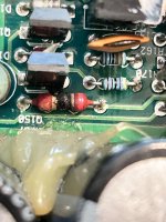
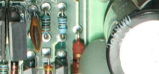
The only thing visible I can find is a burnt resistor R797 that I cannot make out the bands, but it reads 31k in circuit, (see pic).
One leg R797 goes to C726 0.1 uF ceramic disk capacitor that goes to ground.
The other leg R797 goes to C728 0.1 uF that goes to ground. The other way off the same leg of R797 terminates on the top layer of the board and I assuming goes somewhere else, although I have not been able to find what other component it connects to.
Attachments
From your pic it looks possibly RRBG 22 ohm?
Mine, the first band looks pink, I guess it is red, I would have guessed the second band is white (but I don't know) the third band I can't tell, but if its black like in the picture you have it would be a 22 to 29 ohm. Mine is reading 31K.
I cannot find another resistor like this one with similar connections anywhere on the board.
Any guess on what it might be connected to?
Where should I start on this one? Any other schematics that are similar that you can think of?
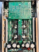
One of the vertical boards has the "F16 and B52" ICs like in the type 1 amp section.
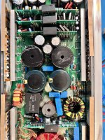
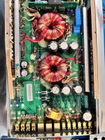
If you have the tutorial, you have this series of photos.
I don't have a diagram and don't know how it's connected. It's odd to have only one in the amp but I don't see any others, either.
It appears to be 22 ohms.
I'd replace this resistor first then see if the amp produces audio on the 4 channels.
I don't have a diagram and don't know how it's connected. It's odd to have only one in the amp but I don't see any others, either.
It appears to be 22 ohms.
I'd replace this resistor first then see if the amp produces audio on the 4 channels.
I tried 8 pcs 1/4 watt 180 ohm resistor in parallel for 2 watt 22.5 ohms and they smoked immediately.
Earlier I was able to tell that one side of R797 also goes to the collector of the C1027 driver transistors and I think the other side may go to the rail caps. Not sure about the connection to the rail cap but that is where the trace disappears. On that side of R797 there is 36 Vdc.
While amp was current limited with a headlamp in series the resistor got to hot to touch within seconds. With the current limiter removed the amp is drawing 6.8 amps and the resistor burns immediately.
There was no audio output either way.
May connect? Use your meter to confirm.
Does it connect to the C1027 driver transistors for all 4 channels?
Does it connect to the C1027 driver transistors for all 4 channels?
I can confirm ,it will mean taking the amp apart, which is fine, but I usually try at first, to do as little disassembly as possible so I don't introduce more problems.
When I mentioned that, I thought it might have rung a bell and been a familiar design.
That is one reason why I was looking for schematics.
Yes, one side R797 connects to the collectors of the C1027s in all 4 channels.
When I mentioned that, I thought it might have rung a bell and been a familiar design.
That is one reason why I was looking for schematics.
Yes, one side R797 connects to the collectors of the C1027s in all 4 channels.
It could be a driver supply. Does the end that you believe connects to the rail read 0 ohms to the tabs of the high-side output transistors?
Have you checked the output transistors to see if any were shorted?
Have you checked the output transistors to see if any were shorted?
I haven't. I knew that was next, actually it would have been one of the first things I checked, but to get to the legs I have to remove the aluminum blocks that hold the FETs against the heat sink. Not being lazy, just not wanting to remove anything if I didn't have to.
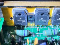
The green stuff on the threads that are sticking through the heatsink blocks, is that loctite or just there for the factory to tell if it has been tampered with?
The green stuff on the threads that are sticking through the heatsink blocks, is that loctite or just there for the factory to tell if it has been tampered with?
The green fixative is likely for tamper evidence. You'll need to put a drop of acetone on it before you attempt to remove the screws.
No shorted outputs. The outputs are mix and match lots, which must have been done from the factory. The lot numbers are different as well as the print/font for the part numbers.
The one leg I thought may have gone to the rail, connects to a small green inductor at the base of the power supply vertical board, not sure right now where it goes from there as I will have to remove that vertical board which unfortunately like everything else on this board is under mounds of silicon . It has 39Vdc on it while the rail is +/- 49Vdc.
What I did find is C728 is reading a short to ground. This is on the side of that resistor that connects to the collectors of the C1027s.
If there are no parallel outputs, they don't have to match. Even if parallel, they could work if not matched but when driven to the limits, I believe that having them matched gives them the best chance of equally sharing current and therefore surviving.
I'd expect a driver supply to be above the rail voltage.
What are the part numbers used for the output transistors?
I'd expect a driver supply to be above the rail voltage.
What are the part numbers used for the output transistors?
What's supplying voltage to the resistor that burned?
If all outputs are N-channel, the high-side drive will need a voltage greater than rail voltage for the output to work efficiently. Do the outputs fed by that resistor drive the high-side output FETs?
If all outputs are N-channel, the high-side drive will need a voltage greater than rail voltage for the output to work efficiently. Do the outputs fed by that resistor drive the high-side output FETs?
I can't figure out what is feeding it. I will work some more trying to trace it.
I have found that it goes to that small axial 47uH inductor then to the cathode of D722 (39Vdc) then anode(30Vdc) is connected to cathode of D723 which is also connected to a 100V 10uf electrolytic (+) then the (-) to the non-inverting speaker terminals.
The resistor is connected to the collector of the C1027 and the emitter of the C1027 is connected the gate of the IRFP150A. This is the same for both output FETs in each channel.
Also the power supply is producing +/- 49V rails, but output FETs have ~+/- 22Vdc on them.
Last edited:
Single strand of wire off of transformer has 19Vpp ac square wave goes to (-) side C724.
(+) C724 has 19Vpp ac square wave centered on +30Vdc . this connects to anode of D722.
Cathode D722 39Vdc goes to R797 through 47uH axial inductor.
With remote disconnected D722 has anode (+ 26Vdc) and cathode has (+ 32Vdc).
(+) C724 has 19Vpp ac square wave centered on +30Vdc . this connects to anode of D722.
Cathode D722 39Vdc goes to R797 through 47uH axial inductor.
With remote disconnected D722 has anode (+ 26Vdc) and cathode has (+ 32Vdc).
That sounds like a doubler circuit. Are you possibly not seeing diodes like D7 or D10 in the attached diagram? Those force the output voltage above the rail voltage (needed for driver supply voltage)?
Could this amp have a lower set of rails for the 4 front channels? That would make sense of the driver voltage no being above 49v.
^^^ That's not all that critical since that resistor is burning. Is the capacitor connected to the output of the burning resistor be shorted?
Could this amp have a lower set of rails for the 4 front channels? That would make sense of the driver voltage no being above 49v.
^^^ That's not all that critical since that resistor is burning. Is the capacitor connected to the output of the burning resistor be shorted?
I cannot see the attachment.
That would make sense. This is a 4 channel class AB with 1 channel class D sub channel. This type of amplifier is completely new to me.
The capacitor C728 0.1uF ceramic disk referenced in #1 and #11 is connected to the output of R797 and appears/reads shorted to ground.
That would make sense. This is a 4 channel class AB with 1 channel class D sub channel. This type of amplifier is completely new to me.
The capacitor C728 0.1uF ceramic disk referenced in #1 and #11 is connected to the output of R797 and appears/reads shorted to ground.
From looking around, yes it looks like a doubler circuit.
With the cap removed the output of R797 is still shorted to speaker ground.
The cap tests good out of the circuit.
With the cap removed the output of R797 is still shorted to speaker ground.
The cap tests good out of the circuit.
- Home
- General Interest
- Car Audio
- Memphis Belle 16-ST1300D
