I’ve recently been testing a basic e-choke for its frequency attenuation performance, as that aspect is somewhat lacking from what I can identify on-line. Testing has allowed a better insight into part selection and also general e-choke operation.
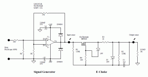
The test jig and e-choke circuit I used is attached below. A two channel PicoScope 4224A and FRA4 gain-phase software are used to measure the e-choke attenuation from ‘input’ to ‘output’, with a simple 1 ohm resistor load. The waveform generator output of the Picoscope is buffered/boosted by the venerable LM12 power opamp, which achieves a flat large-signal amplitude out to 100kHz, and -20dB out at 400kHz. The signal generator and FRA4 software allows a dc voltage offset to be included with the ac signal, which can then apply a practical DC voltage across the e-choke DUT, along with substantial AC voltage to allow gain-phase measurement across the e-choke, given that e-choke applications for say valve amps require an e-choke providing circa 100mAdc. The e-choke dc current is normally determined by the application amp's operation, but for the purposes of this test the e-choke dc current is set by applying a dc voltage from the buffer to the input of the e-choke.
The low frequency operation of an e-choke is explained in a few on-line references. In summary, the resistor divider R1:R2 sets the idle Vds voltage of the fet for a given e-choke dc current. This is done by applying a Vgs-on voltage consistent with the dc voltage drop across R3 and the specific Vgs-on characteristic of the FET used. For example, with an input voltage of 10Vdc, and Idc=100mA through R3=20 ohm, the Vgs-on=3V as R1:R2 sets Vgs-on + Idc.20 = 5V. In a class A amp application with a constant current draw, the idle voltage drop across the e-choke will vary somewhat as the FET Vgs-on voltage characteristic is temperature dependent, but would otherwise be constant.
An input ripple voltage causes Vds to vary similarly by way of C1 keeping Vgs pseudo-constant with a characteristic that emulates an inductance (effective impedance of the e-choke increases with frequency by way of C1 impedance falling with frequency). Vds negative swing is limited when Vds approaches FET on-voltage (~0V), so a symmetrical swing of Vds is about twice the idle Vds voltage – which then relates to the maximum incoming ripple voltage that the e-choke can linearly attenuate.
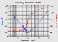
With respect to frequency response of attenuation, the impedance of C1 approaches zero above ball-park 1kHz, and so gain (attenuation rate) then changes from -20dB/decade back to unity. Above nominal 1kHz the effective capacitance across the FET (drain-source) starts to become significant such that FET impedance becomes capacitive and dominant, and the e-choke gain increases at +20dB/decade back towards unity. This frequency response is equivalent to that of a common iron-cored choke where choke impedance rises with frequency but then reaches a peak at the choke self-resonance frequency, and then falls as the shunt capacitance of the choke winding then dominates.
Of interest with the test measurements was the influence of FET capacitance. With an IRF840, the maximum e-choke attenuation reaches about -90dB at 1kHz before the impact of FET capacitance then starts to dominate, and at higher frequency represents a drain-source capacitance of about 2.9nF. The IRF840 has a datasheet Coss of about 2nF at Vds=1V, so it seems like the FET gate resistor and/or a Miller effect may be at play.
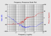
Changing to a MTD1N80 FET, with a significantly lower datasheet Coss of 320pF at 1V, did push out the frequency to above 10kHz where e-choke attenuation starts to fall, and the response represents a drain-source capacitance of about 510pF. Increasing R4 certainly showed a dominating influence.
This is all food for thought perhaps, although I don't think many have used e-chokes, and fewer have likely checked their performance.
Ciao, Tim
PS. excuse the error in LM12 gain, and the phase axis numbering in the middle plot.
The test jig and e-choke circuit I used is attached below. A two channel PicoScope 4224A and FRA4 gain-phase software are used to measure the e-choke attenuation from ‘input’ to ‘output’, with a simple 1 ohm resistor load. The waveform generator output of the Picoscope is buffered/boosted by the venerable LM12 power opamp, which achieves a flat large-signal amplitude out to 100kHz, and -20dB out at 400kHz. The signal generator and FRA4 software allows a dc voltage offset to be included with the ac signal, which can then apply a practical DC voltage across the e-choke DUT, along with substantial AC voltage to allow gain-phase measurement across the e-choke, given that e-choke applications for say valve amps require an e-choke providing circa 100mAdc. The e-choke dc current is normally determined by the application amp's operation, but for the purposes of this test the e-choke dc current is set by applying a dc voltage from the buffer to the input of the e-choke.
The low frequency operation of an e-choke is explained in a few on-line references. In summary, the resistor divider R1:R2 sets the idle Vds voltage of the fet for a given e-choke dc current. This is done by applying a Vgs-on voltage consistent with the dc voltage drop across R3 and the specific Vgs-on characteristic of the FET used. For example, with an input voltage of 10Vdc, and Idc=100mA through R3=20 ohm, the Vgs-on=3V as R1:R2 sets Vgs-on + Idc.20 = 5V. In a class A amp application with a constant current draw, the idle voltage drop across the e-choke will vary somewhat as the FET Vgs-on voltage characteristic is temperature dependent, but would otherwise be constant.
An input ripple voltage causes Vds to vary similarly by way of C1 keeping Vgs pseudo-constant with a characteristic that emulates an inductance (effective impedance of the e-choke increases with frequency by way of C1 impedance falling with frequency). Vds negative swing is limited when Vds approaches FET on-voltage (~0V), so a symmetrical swing of Vds is about twice the idle Vds voltage – which then relates to the maximum incoming ripple voltage that the e-choke can linearly attenuate.
With respect to frequency response of attenuation, the impedance of C1 approaches zero above ball-park 1kHz, and so gain (attenuation rate) then changes from -20dB/decade back to unity. Above nominal 1kHz the effective capacitance across the FET (drain-source) starts to become significant such that FET impedance becomes capacitive and dominant, and the e-choke gain increases at +20dB/decade back towards unity. This frequency response is equivalent to that of a common iron-cored choke where choke impedance rises with frequency but then reaches a peak at the choke self-resonance frequency, and then falls as the shunt capacitance of the choke winding then dominates.
Of interest with the test measurements was the influence of FET capacitance. With an IRF840, the maximum e-choke attenuation reaches about -90dB at 1kHz before the impact of FET capacitance then starts to dominate, and at higher frequency represents a drain-source capacitance of about 2.9nF. The IRF840 has a datasheet Coss of about 2nF at Vds=1V, so it seems like the FET gate resistor and/or a Miller effect may be at play.
Changing to a MTD1N80 FET, with a significantly lower datasheet Coss of 320pF at 1V, did push out the frequency to above 10kHz where e-choke attenuation starts to fall, and the response represents a drain-source capacitance of about 510pF. Increasing R4 certainly showed a dominating influence.
This is all food for thought perhaps, although I don't think many have used e-chokes, and fewer have likely checked their performance.
Ciao, Tim
PS. excuse the error in LM12 gain, and the phase axis numbering in the middle plot.
Attachments
Last edited:
