Hi all, trying to assemble a music system that a tri of year 4 primary schoolers may plug various instruments into for practice. This needs to double up as a bass amp for my daughter for her electric bass classes at school. She is used to the little sub plugged into our mixing desk at home and like me she hates the weak uninspiring sounds that the usual suspects in the music shop make in the sub $1500 mark. Our usual listening and playing stuff is West Indian including dub
For $35 I found a group of four Logitech 2.1 systems that included the one that was the same z623 model sub we use. Issue was that this one didn’t have the satellites in lot. The left satellite contains the controls and plugs into a DB15. The right satellite plugs into a dedicated rca. Rear panel also has rca and 3.5mm inputs. The missing satellite has another 3.5mm input as well as headphone out, bass level knob, volume knob
In that lot there were satellites from LG as well ones for the other smaller three subs
I have a little USB/battery powered mixer with Bluetooth, instrument in and aux in
Also have two Kemo M040n black box preamps, 18 volts of battery, 18v dc wart, 9v dc wart, pots and passives for passive tone controls, passives to build four sets of the MPF102 jfet pres from another thread
Add to the list some knobs, wheels, mdf, marine ply, upholstery fabric, carpet, retractable handle from bag
Hoping to fit the sub and a pair or two of satellites into another new box and something the gyals may plug things like electric bass, upright bass pickup, mic, electric guitar, electronic drum set, tablet and like. Basic controls to find basic sounds
First challenge is to decode the DB15 pinout. I know that the pins for discrete input for the sub section and standby from the net searches. Plugged into this pin with the little mixer and bass guitar sounds sweet but the loudness is absent. Swapping the satellites from the home system and plugging the mixer into that returns the loudness
Now I am going to try to cascade (is this the right word, please advise) one Kemo into passive bass and treble tone circuit assembled from net schematics. That will be followed by another Kemo. Both Kemo will have 10k pots on the input lead. I’ll plug the bass into this and hook it to the sub direct pin and see if I can get acceptable volume and tone control
Hoping this works, then I’ll have the starting of a bass amp that my kid may find inspiring and satisfying to play
Next thing to attempt is finding the direct ins for main speakers amps in that DB15. For this I will need to make or buy a three instrument channel plus stereo mixer and 2.1 filter
As a side I have been curious about the MPF102 jfet. I have some and the parts needed to build some internet schematics. First attempt at building from random schematics as well as trying to learn about circuits like these pres ans mixers
Hope to find some assistance here if I get stuck. Thanks and regards
Randy
Old electric guitar converted to bass strings. With my bridge tuner mod and locked at nut, kid friendly and won’t go out of tune. 25” scale. Stock electric guitar pickups handling four bass strings just fine it seems. Anyone know why?
Bass plugs into Kemo pre via 10k pot and pre plugged into sub direct in. No tone adjustment at the moment but sounds amazing so far. The pre did the job. Next test will be 18v via battery for the pre and then plug pack power to see if all stays noise free
This is the hack for discrete input to the sub amp. The blue loop is the standby power. I would like to place a pretty looking switch there with an indicator LED. Can anyone please help with the correct procedure for measuring the voltage on that loop and if that can power the indicator LED?
Tried the Kemo pre with 18v. Sounds very good. Every fret comes through with authority and is musical at even very high volumes and as most know, the Z623 can get loud and carries a THX rating (if that means anything now, some years ago folks used to wet themselves on seeing a THX badge. I think only Yamaha decided to ignore THX. I have only had higher end Yamaha HT receivers, so my THX experience is limited to the Z623 and the 5.1 version)
I still haven't done anything with the components for tone and jfet pres. Hoping to get some assistance with someone knowledgeable with these to see if the values can be optimised for my particular use
One this about the Kemo is a hum that is not present when volume knob is full left and increases with volume increase. What things can induce hum like this? Is it a screening issue or supply?
View attachment 1027208
This is the hack for discrete input to the sub amp. The blue loop is the standby power. I would like to place a pretty looking switch there with an indicator LED. Can anyone please help with the correct procedure for measuring the voltage on that loop and if that can power the indicator LED?
This net find appears to contain errors. I do not know enough to say this with authority. I tried to learn my way around the multimeter and then decode the DB15. For example, in that image, the standby loop is connected to pin 5. Well, pin 5 gives me positive in for one of the amp channels! I do not understand why they connected the standby to pin 5. Shorting pin 15 to ground or any of the three input channel's positive pin turns the system on. The input pins are not direct wire connections, there are some SMD resistors and caps on the PCB and there is input impedance present at the RCA and 3.5 connectors. Look like pin 5 shorted to even resistive paths to ground will turn it on. I think I have worked it out as I now have direct access to all the pins and system functions and there appears to be a logic to how the connections are implemented. I want to share my finding on this so that it may help others with this system. I'll do a post on it when I get a chance and continue carrying on like an idiot with this monologue
Thanks and regards
Randy
Building the new cabinet today. I won't be taking the parts out of the original Z623 cab. I will instead use 6mm marine ply over it as veneer and extend the sides taller than the original box height to form an upper tier space to install the fulranges and all the new electronics...... unless someone has a good argument on why this would be a bad approach
I had the same idea a while ago for one of my projects (turning a pair of thrift-store boom-box speakers into a small portable guitar/vocal amp). I can't imagine why it wouldn't work....6mm marine ply over it as veneer and extend the sides taller than the original box height to form an upper tier space...
")
Many of these subwoofer / satellite systems have a huge "hole" in the frequency response, where the subwoofer can't reach high enough frequencies, and the tiny satellites can't reach low enough frequencies. Hopefully the additional speakers you're adding will eliminate that hole.
I wish I could help with some of your other questions, but unfortunately, I've never laid eyes on this particular speaker, so I don't know anything about it.
-Gnobuddy
The original low pass built into that seems quite higher than a true sub, I think this is built more like a 2 way with a shared bass driver that can go low and loud and crossed around 200-300hz. There is not much separation designed in with the length of wire between speakers, so the holes aren't that apparent. A large "ramp" is apparent as there appears to be a boost for the sub built in. Since I am going direct-in to the amp modules, the original filters and eq curves no longer apply. I am fitting a pair of 3" LG full ranges in series to each L and R amp modules to match the 8Ω of the original smaller single full range per side. Intuition says that this will bring better balance and lower that "ramp". I am also at the moment trying to read up on DIY tone controls. I have a new interest in inserting at least 6 bands of eq covering 20-300hz on the bass guitar input to shape that input and 6 bands covering 20hz-20khz on the master stereo bus to shape that system "ramp" to the room on the day if required. (I am thinking about implementing a less accessible type knob system here to deter fiddling) Found lots of vids on YouTube on making multi band eq's and at the moment trying to understand filter design, so I can select a schematic and adjust the filter points to my requirements.........Many of these subwoofer / satellite systems have a huge "hole" in the frequency response, where the subwoofer can't reach high enough frequencies, and the tiny satellites can't reach low enough frequencies. Hopefully the additional speakers you're adding will eliminate that hole...........
I am starting learning from scratch and trying to find an easy and low-cost way to scope the outputs to see the results in wave form too. Also trying to find ways to send test signals. I picked up a new multimeter
https://www.jaycar.com.au/economy-t...os=1&queryId=668941161a108bc6f481f490a3adcebf
I don't know all that much about using it, though, still learning. I need to read the manual on what things it can't do for audio testing and find some value supplements to run alongside that. I also picked up a new soldering station with holders, lights and a good lens as well as some neater straight and bent nose pliers and cutters
On YouTube, it appears that point to point can be done easily, looks neat and attractive as well as durable. I think if I hot glued such circuits into the enclosure, then I won’t have to worry about falls and knocks. Changing parts or modules will be as easy as snip and solder too
Having to learn to ground up is also giving me the determination to go all the way and make it a good, powerful system designed specifically for kids
We are having some other difficulties at the moment. Where we are, we just barely missed out on some deadly floods by about 20kms due to some weather directing geographical features, but have been cutoff for a few days. So many people had to leave their vehicles where parked as the town ran out of fuel. The stores were empty too. Supplies are only just starting to trickle through. Yesterday the state government shut down the schools in the middle of the day as another extreme weather event forecast and the schools remain closed today
Haven't had the chance to work on cabinet yet. At the moment, trying to learn filters and hoping for the outside workbench to dry up a bit
Thank you for taking an interest
Regards
Randy
I think the "hole" is because the tiny satellite drivers seem to struggle to get below 400 - 500 Hz, while the heavy woofer driver aimed at your ankles struggles to reach above 150 - 200 Hz.The original low pass built into that seems quite higher than a true sub, I think this is built more like a 2 way with a shared bass driver that can go low and loud and crossed around 200-300hz.
In other words, the hole in the frequency response isn't caused by badly-designed crossover filters - it's caused by the mechanical limitations of the speakers used. Specifically, the desire to make the satellite speakers as tiny as possible, which forces the use of tiny speakers that can't move enough air to produce lower frequencies.
Blame Bose, the charlatan audio company that made the first of these systems I know of. Bose has a long history of making bad audio products based on some kind of "shtick" or the other, popularizing them with tons of consumer advertising, then selling them at very high prices.
The hole in the frequency response may not be as much of a problem when used for bass guitar, rather than music. With a little luck, the subwoofer will reproduce the fundamentals from the bass, and the satellites will reproduce the higher frequencies that give the bass its timbre and help it to be audible in the mix.
There is free software out there, that lets you use the sound card in a computer as a crude oscilloscope. It has many limitations, but may be adequate for your purposes....trying to find an easy and low-cost way to scope the outputs...
A multimeter is a very good thing to have if you're tinkering with electronics. Good move!
How hot does it get in your area in summer? In places like Arizona, hot glue softens and turns to goo if left in a parked car in full sunshine....hot glued such circuits into the enclosure...
I see you are on the coast, and maybe that keeps summer temperatures from getting too nuts. But then again, you are in Australia, a famously sun-drenched country...
There are guitar pickup manufacturers who think "wax potting" the coils are a good idea. It works quite well in cold climates. In hot sunny places, the wax melts, runs out of the pickup, and contaminates the wooden guitar body.
Glad to hear you're okay. What a nightmare!...we just barely missed out on some deadly floods by about 20kms due to some weather directing geographical features, but have been cutoff for a few days...
We had our own deadly floods in BC in mid-November. Roads and bridges washed away, cities flooded and needing evacuation, tens of thousands of farm animals drowned. Horrible stuff.
A friend of mine in Greece emailed me that his city was immobilized for days by extraordinary amounts of snow, with empty stores and stranded vehicles, just as you described.
Insanely extreme weather is occurring more and more frequently all over the world. Humanity is in big, big trouble, and we haven't woken up to it yet.
-Gnobuddy
Learning how filters and tones are configured raises another question. I don't think it's only eq'ing of particular frequencies that shape sound. From careful listening to the harmonics (am I using this term correctly? Please educate) produced around each fret and how that fret is played, I have come to the belief that to shape sound from an instrument;
1 - multiple bands of eq in the relevant area of the instrument, at least 4 bands for a bass instrument. I think apart from the level pot, this is the first shape step to shape a frequency curve, but this doesn't alter the "voice"
2 - each band should have two parallel circuits that are more complex and contain a high pass to one side and low pass to the other. These two adjacent circuits need level pot, range pot, delay pot and reverb pot. The "voice" circuits to then mix back into the that tone bands output
This is the only way I can see to truly shape a bass guitar "voice" with analog. So each tone band consists of tone knob, upper harmonics level and reverb and lower harmonics level and reverb. My own voice is fairly low to where a lot comes from the subwoofer too. I can "shake" and add inflections while singing to suit the moods of different songs. Indian music composer R.D. Burman had his own unique singing style that he distorted with gargling type sounds at various reaches. With this, I infer that a distortion level on each of that three parallel circuits per band will do a job too
Basically this means that each band of the tone controls get 9 knobs or so. This is just my thots from what, I don't know whether it's on to something or coming from ignorance. After I finish the amp/cab to a usable level, I am going to seriously learn to implement this. I haven't seen it done like this before and if I am the first one to think of this break down then I would enjoy it to be known after me as the "Bassinga" (bass singer) system. If it's already old news to split each band and adjust harmonics individually like this, then I hope someone points it out
Not if wired according to the schematic. But it's not ready for prime time:Will it go up in flames if I put this together?
1) The input needs to be fed from a very low-impedance source. The only way to guarantee this is to add one more op-amp, between input and the left end of the circuit you showed, configured as a voltage follower (or non-inverting amplifier with small gain if needed).
2) You will not easily find 24nF caps. 22nF is the standard value. You can make 24.2 nF by paralleling 22nF and 2.2nF, but it will nearly double your capacitor costs; why not just design for 22 nF?
3) Same issue with resistor values. 10.8k is unobtanium, 11k is standard in the E24 range ( https://www.asenergi.com/pdf/resistors/standard-resistor-values-e24.pdf ).
Note that the difference between 10.8k and 11k is only 1.8%; unless you use 1% tolerance resistors, and 1% tolerance capacitors (hard to find and expensive), there is no difference.
Similarly, 9.53k, 49.5k, 7.88k, 4.66k are all very exotic values that will be hard to find.
Bigger questions (and I am trying to be helpful, to save you money and time, not to dampen your enthusiasm): You are working with a subwoofer with an unknown frequency response, and satellite speakers also with unknown frequency response.
4) How do you know that 200 Hz is the right crossover frequency to mate them?
5) How do you know a Bessel alignment is the right one?
6) Why make a crossover network with 1% tolerance, when we don't know the speaker's own performance to even +/- 50%?
7) What sort of low-pass filter is already built into the subwoofer, and why do you need to change it?
In post #2, you wrote "...sounds amazing so far". If it already sounds good, why mess with building expensive filters that may not do anything good, since you have no measurements on the existing driver behaviour?
What I'm driving at is: if it already sounds good, why not just blue the satellites on top of the sub, or build a box around the pair to hold them together, and enjoy as-is? If you want to add stuff, rather than muck about with the existing frequency response (which already sounds good to you), why not add things that are useful, like tone controls, maybe a little overdrive circuit for some growly bass, maybe a simple compressor, which many bass players like?
-Gnobuddy
Not if wired according to the schematic. But it's not ready for prime time:
1) The input needs to be fed from a very low-impedance source. The only way to guarantee this is to add one more op-amp, between input and the left end of the circuit you showed, configured as a voltage follower (or non-inverting amplifier with small gain if needed).
Is apparent that I am not quite there with understanding of such things to "design" a functional circuit yet
2) You will not easily find 24nF caps. 22nF is the standard value. You can make 24.2 nF by paralleling 22nF and 2.2nF, but it will nearly double your capacitor costs; why not just design for 22 nF?
3) Same issue with resistor values. 10.8k is unobtanium, 11k is standard in the E24 range ( https://www.asenergi.com/pdf/resistors/standard-resistor-values-e24.pdf ).
Note that the difference between 10.8k and 11k is only 1.8%; unless you use 1% tolerance resistors, and 1% tolerance capacitors (hard to find and expensive), there is no difference.
Similarly, 9.53k, 49.5k, 7.88k, 4.66k are all very exotic values that will be hard to find.
The wizard lets you choose the -3db and set a slope, e.g. -24db point. Then you have to pick how many stages. The closer the two points, the more stages needed. The next tab in the wizard lets you set tolerances. I just checked what seemed to be the closest tolerance options. Same with the component values. I haven't looked up availability yet, I just assumed that the wizard will use regular values because I thot it had a built-in component library
I need to find out if I can design a schematic in LTSpice and have the program run a frequency response plot
In post #2, you wrote "...sounds amazing so far". If it already sounds good, why mess with building expensive filters that may not do anything good, since you have no measurements on the existing driver behaviour?
At the moment I have a working mono preamp circuit with the bass plugged in and plugged into the sub poweramp driving the low frequency driver to its range limits and sounding very good on all bass frets, so I have the beginnings of a bass amp
Problem?
Missing any filter networks to make use of the satellite poweramp inputs, no built-in crossovers. That was in the control pod and is missing and what I need to replicate to make use of the full 2.1 amp sections. The original crossover point appears to be around 200hz. I have another fully working system that is of the same model and currently in use as a home bass monitor
Have to realise that this project is only up to the poweramps and drivers at the moment. I have a selection of full ranges and 2 ways that I can implement as tops
4) How do you know that 200 Hz is the right crossover frequency to mate them?
5) How do you know a Bessel alignment is the right one?
With bass guitar output being classed at around under 30hz to around 400hz including the harmonics, and the 7" Logitech driver doing a great job alone in that range, I thot to stick around the original crossover point. The Bessel filter was decided by the wizard with the numbers that I entered for filter points and number of desired stages. I tried to stick to one dual opamp that can accommodate two stages. I am not able to enter component values into the wizard, only filter points and a slider for number of stages which then determines Bessel or other
Hope this makes sense
Thanks and regards
Randy
I'm attaching a functional circuit (drawn and simulated in LTSpice) that does pretty much what your own circuit does, but it does not need exotic resistor or capacitor values. It does need one more op-amp, to buffer the input.Is apparent that I am not quite there with understanding of such things to "design" a functional circuit yet
While integrated circuits that include two op-amps are popular (TL072, for instance), there are also chips that contain four op-amps, such as the TL074, which is pretty much two TL072 chips in one.
By the way, I've never seen Bessel filters used in a crossover network. They provide much cruder frequency control than Butterworth filters, so those used to be the most commonly used ones. These days it's more likely to be Linkwitz-Riley filters, which are slightly tweaked Butterworth filters.
But before you build your active filter...let's talk about if you actually need it!
Computers are still a lot stupider than people (Donald Trump excepted)....The wizard...
The filter wizard you used crunched through some math (which computers are good at), and came up with a theoretically ideal filter. But the wizard does not have a clue about the bigger picture.
For instance, the wizard doesn't know that you are working with a subwoofer that already has a frequency response that sounds good to you, that you don't care about +/- 0.1% accuracy (but do care about the high cost of such components), et cetera.
Some questions (to help you pin down what you need, and help me understand what your goals are):...At the moment I have a working mono preamp circuit with the bass plugged in and plugged into the sub poweramp driving the low frequency driver to its range limits and sounding very good on all bass frets...
8) If the subwoofer already sounds good to you as a bass amp, why do you want to change its frequency response with an external 200 Hz low-pass filter? This would rob you of frequencies above 200 Hz, and might make your bass sound dull and lifeless.
9) Since the subwoofer sounds good with bass by itself, why do you want to add the satellites? What function do you have in mind for them?
10) If you do want to add the satellites, don't you need high-pass filters for them, rather than a low-pass filter for the subwoofer?
Keep in mind that building all these filters quickly turns into a can of worms. One 4th-order low-pass filter for the subwoofer already requires three op-amps. Then you need two high-pass filters for the satellite speakers - if they are also to be 4-th order, there go six more op-amps, and another handful of precision resistors and caps.
If the satellites are themselves two-way (separate tweeter), then you need another low-pass for each midrange driver, and another high-pass for each tweeter. I think we're up to 18 op-amps now, plus a large beer-mug full of precision caps and resistors. And a couple of weeks to build, test, and debug all of this.
I got the impression that this was a quick-n-dirty project on a small budget to play bass through (which is an entirely valid plan, and I think the idea to use a consumer speaker subwoofer was ingenious). If I'm right, you probably don't want to launch into all this additional complexity, building and testing tons of active filters in order to include satellite speakers - which you don't actually need, since the sub sounds fine with your bass guitar.
So why not just enjoy the subwoofer as bass amp, as you already are doing? (Maybe I'm missing something you posted earlier, if so, my apologies.)
By the way, depending on type of bass, and style of playing, there may be frequencies well above 400 Hz in the output of a bass. Slap-style bass produces lots of higher frequencies; bright round-wound strings produce more high frequencies; playing with a pick (rather than fingers) produces more treble; using something more like a Jazz-bass rather than a P-bass produces more treble.
So it may be that your subwoofer sounds best (for playing a bass guitar through) without adding any additional low-pass filtering.
You can, indeed! I just did this, and you can see a screenshot of both circuit and simulated frequency response attached below.I need to find out if I can design a schematic in LTSpice and have the program run a frequency response plot
I'm also attaching the actual LTSpice simulation file ("hipass001.asc"), which you can open up in LTSpice and tinker with, if you like.
You'll also need the TL072 LTSpice model, so I'll attach that as well.
When I started trying to learn how to use LTSpice some years ago, I found a set of online tutorials by Simon Bramble that were incredibly helpful: http://www.simonbramble.co.uk/lt_spice/ltspice_lt_spice.htm
-Gnobuddy
Attachments
I'm attaching a functional circuit (drawn and simulated in LTSpice) that does pretty much what your own circuit does, but it does not need exotic resistor or capacitor values. It does need one more op-amp, to buffer the input.
Part 1
Before I get into anything else, please allow me to say thank you for taking an interest. I have always enjoyed your contribution in all the discussions you take part in. I believe you understand the spirit of discussion and bouncing thots off others. Your spice models will be very helpful in understanding filters. I have a comprehensive schematic for a low and high pass 2.1 system based on TL072. I haven't been able to work out the filter points in that circuit to see if I can use that, and starting from scratch is an appealing thot
8) If the subwoofer already sounds good to you as a bass amp, why do you want to change its frequency response with an external 200 Hz low-pass filter? This would rob you of frequencies above 200 Hz, and might make your bass sound dull and lifeless.
This system is primarily a bass amp for my daughter. Her two friends will join her for practice. Instruments plugging in will range from bass, electric guitar/ukulele pickup, mic, and a Roland JDXI. The filters are where I thot to start with to enable the use of the built-in 35wrms x2 amp to turn this into a self-contained PA system. Right now it is a self-contained bass amp. I plan to slowly evolve it to the PA as I learn about electronics
I started trying to understand the low pass stage first for no particular reason, I have to understand the high pass side too
Next I have to learn about a summing stage
Then I have to learn to duplicate the input stages and tone controls for them
Then learn about overdrive stages for the guitar channels
Then learn about implementing proper pre and post fader channel sends
(This is where the JDXI comes in. It has this crazy vocoder function called auto note. There is a mic input on it that I want to send the mic signal to when required, and it has a guitar input that I want to send the guitar signals to when required and/or a mix of guitars and mics signal post fader to the guitar input. The JDXI has the ability for its different parts to be played simultaneously and independently by external input sources like the vocoder inputs, midi, and its own keyboard and sequencer. The vocoder section features a wet channel and a dry channel, so the post fader instrument dry signal can always be present to its internal stereo bus. The JDXI has stereo outputs for plugging back into a stereo channel on the summing stage. It will now also act as the USB interface between the system and an iPad, enabling recording as well as playback from GarageBand and media library. My daughter is competent enough with GarageBand and iPad, and I believe she has the ability to learn the JDXI routing. I hope this makes sense. Please look up the JDXI auto note function on YouTube)
9) Since the subwoofer sounds good with bass by itself, why do you want to add the satellites? What function do you have in mind for them?
Please see above, this it to convert it to a PA system rather than just bass amp duties. I have a broad selection of full ranges and two ways from the reuse centre. To start with, I will fit a pair of full ranges in dedicated compartments to the extension to the original sub cabinet. A compartment in this extension will contain the additional electronics. An evolution will be to fit switched TRS sockets inline between the stereo amp and speakers so that I can plug in larger two ways on stands and disable the internal full ranges. I hope this make some sort of crazy sense
10) If you do want to add the satellites, don't you need high-pass filters for them, rather than a low-pass filter for the subwoofer?
I started on the low pass for no particular reason. I have to learn the other side too
Keep in mind that building all these filters quickly turns into a can of worms ......................................................................... And a couple of weeks to build, test, and debug all of this.
I got the impression that this was a quick-n-dirty project on a small budget to play bass through (which is an entirely valid plan.................................................................... If I'm right, you probably don't want to launch into all this additional complexity, building and testing tons of active filters in order to include satellite speakers - which you don't actually need, since the sub sounds fine with your bass guitar
Sorry man, I must have been adding so much textual input that I am afraid I am making it difficult to present current state. My apologies for trashing your message quote above, the intention is to address a particular point and no rudeness is present. I recognise that the text medium is not able to easily convey emotion
The quick and dirty bass amp stage has been achieved except for the lack of tone controls. This project is not about budget, as I will explain in a bit. I am now at the start of implementing full 2.1 channel ability. I hope this makes sense. And above is a road map for evolving this unit, and now I will try to explain why I want to get involved to this level
Part 2
Two factors at work here. Firstly, I have always been moved by the sound of bass, I have spent considerable energies in developing some bass delivery speakers over the last 30yrs, and I don't mean and amp for the bass guitar rather a general purpose bass speaker that can tuned into an instrument or playback monitor at the manipulation of a mechanical control. This is to achieve that type of sound that I find awesome and pleasant to hear. This so far has been about the musicality and authority that is being produced, rather than how the speaker box measures. To achieve this state, I ended up with extended range subwoofer drivers and to achieve the frequency response implementation that I want needs that extended range driver to also have extended range power handling and excursion. I have found three such drivers over time and the fourth also coming in the smallest in the Logitech Z623. When we moved state, I had to leave most of my stuff in storage at my folk's place. We acquired a Yamaha MG12XU, keyboard, electric guitar, electric drums, basses after moving here. I had some previous history with the Logitech system and thot to pick one up and plug that into the mixer as the 2.1 monitor. The satellites are nothing to get excited about, but the low end is gorgeous. (I have a concurrent project building a pair of new satellites with a pair of 6.5 inch coaxials that auditions gorgeous too. These are unconventional drivers for this use, and I fear ridicule)
For the last three years, this is what we have been making music on. My little one is so spoilt by the quality of the low end at home that she looks at shop amps with contempt. None of the bass amps in the shop sounds as pleasant and authoritative to her. So I went and bought a second system to convert that to an amp for her. Then I saw one sub unit only at the reuse centre and returned the second system still unpacked and now working with this. I have always encouraged reuse with my kid, and this seemed also a good life lesson opportunity for her. I hope this makes sense too
If you can remember, three years ago, there was a down on his luck taxi driver looking to make a very short scale electric bass for practising in the cab while waiting on the taxi rank. That was me. Anyway, the industry kept on falling apart due to impact from so-called "rideshare" model. I stuck it out for a few more months, and then we made a big life change. I left the taxi industry, and we moved from Sydney to Hervey Bay, nearly, 1400 km away. This is a little coastal town popular with tourists for whale watching, fishing and other marine activities. We moved here to set up a boat hire business. Four vessels ranging from houseboat to fishing boats. I had an accident some months back ad still receiving wound care, so work on the boats are on hold till recovery. In the meantime, my better half has been very supportive and encouraged developing our music ability as well as equipment and skills and ability with DIYing
Three years ago when I originally joined this site, I made a prototype shorty using a bit of plank, and it is now the preferred sound over all the other basses in our local music shop. "Planky" is very highly respected, and I get interest all the time with folks wanting me to build them one, but I haven't been inclined as I never ended up completing the proper one. The body work is done, I have most parts and all the special strings and everything. Just lost interest as planky sounded so good, and I had a full sized bass too as well, the need for the shorty had gone. I had been thinking to join the cottage industry making more "plankies". I have always had the aspiration to use my development work in acoustically voice controlling a low frequency speaker and offering that in a bass amp format. Just something boutique and very hand made type scale. I judge myself as a highly effective craftsman with ability to implement fine detail and pulling off the mental image model into a real crafted object. I would like to take time available due to injury to learn about the electronic side of things regarding the amp. The kids amp project came along just in time for jumping into the larger aspirations. I don't really need to develop too many fancy electronics for that as existing prebuilt modules on the market can take care of all the amp duties with that too. But when it comes to the pre stages, there is nothing that suits the type of signal routing and manipulation without also offering a ton of other functionality that I need for driving my amps for my speaker development. My daughter's project is a foot in the door with learning about these electronics. Hopefully, I will be able to pick up the competency to tackle more complex designs of my own. I have to start somewhere
And the shorty I was building, even though I stopped work on it, it is something again. No amount of imagination can prepare one for what I am holding here. It took me one full year of effort with a scalpel on the bodywork on a piece of rock hard Australian spotted gum heart wood hard wood timber! I am not ready to show a pic of it until I have finished it. I have all the parts, but it is fourth in the list of audio projects
My apologies with the scale of the message, I hope it's not too painful to wade through
......... and I think the idea to use a consumer speaker subwoofer was ingenious).
Two factors at work here. Firstly, I have always been moved by the sound of bass, I have spent considerable energies in developing some bass delivery speakers over the last 30yrs, and I don't mean and amp for the bass guitar rather a general purpose bass speaker that can tuned into an instrument or playback monitor at the manipulation of a mechanical control. This is to achieve that type of sound that I find awesome and pleasant to hear. This so far has been about the musicality and authority that is being produced, rather than how the speaker box measures. To achieve this state, I ended up with extended range subwoofer drivers and to achieve the frequency response implementation that I want needs that extended range driver to also have extended range power handling and excursion. I have found three such drivers over time and the fourth also coming in the smallest in the Logitech Z623. When we moved state, I had to leave most of my stuff in storage at my folk's place. We acquired a Yamaha MG12XU, keyboard, electric guitar, electric drums, basses after moving here. I had some previous history with the Logitech system and thot to pick one up and plug that into the mixer as the 2.1 monitor. The satellites are nothing to get excited about, but the low end is gorgeous. (I have a concurrent project building a pair of new satellites with a pair of 6.5 inch coaxials that auditions gorgeous too. These are unconventional drivers for this use, and I fear ridicule)
For the last three years, this is what we have been making music on. My little one is so spoilt by the quality of the low end at home that she looks at shop amps with contempt. None of the bass amps in the shop sounds as pleasant and authoritative to her. So I went and bought a second system to convert that to an amp for her. Then I saw one sub unit only at the reuse centre and returned the second system still unpacked and now working with this. I have always encouraged reuse with my kid, and this seemed also a good life lesson opportunity for her. I hope this makes sense too
If you can remember, three years ago, there was a down on his luck taxi driver looking to make a very short scale electric bass for practising in the cab while waiting on the taxi rank. That was me. Anyway, the industry kept on falling apart due to impact from so-called "rideshare" model. I stuck it out for a few more months, and then we made a big life change. I left the taxi industry, and we moved from Sydney to Hervey Bay, nearly, 1400 km away. This is a little coastal town popular with tourists for whale watching, fishing and other marine activities. We moved here to set up a boat hire business. Four vessels ranging from houseboat to fishing boats. I had an accident some months back ad still receiving wound care, so work on the boats are on hold till recovery. In the meantime, my better half has been very supportive and encouraged developing our music ability as well as equipment and skills and ability with DIYing
Three years ago when I originally joined this site, I made a prototype shorty using a bit of plank, and it is now the preferred sound over all the other basses in our local music shop. "Planky" is very highly respected, and I get interest all the time with folks wanting me to build them one, but I haven't been inclined as I never ended up completing the proper one. The body work is done, I have most parts and all the special strings and everything. Just lost interest as planky sounded so good, and I had a full sized bass too as well, the need for the shorty had gone. I had been thinking to join the cottage industry making more "plankies". I have always had the aspiration to use my development work in acoustically voice controlling a low frequency speaker and offering that in a bass amp format. Just something boutique and very hand made type scale. I judge myself as a highly effective craftsman with ability to implement fine detail and pulling off the mental image model into a real crafted object. I would like to take time available due to injury to learn about the electronic side of things regarding the amp. The kids amp project came along just in time for jumping into the larger aspirations. I don't really need to develop too many fancy electronics for that as existing prebuilt modules on the market can take care of all the amp duties with that too. But when it comes to the pre stages, there is nothing that suits the type of signal routing and manipulation without also offering a ton of other functionality that I need for driving my amps for my speaker development. My daughter's project is a foot in the door with learning about these electronics. Hopefully, I will be able to pick up the competency to tackle more complex designs of my own. I have to start somewhere
And the shorty I was building, even though I stopped work on it, it is something again. No amount of imagination can prepare one for what I am holding here. It took me one full year of effort with a scalpel on the bodywork on a piece of rock hard Australian spotted gum heart wood hard wood timber! I am not ready to show a pic of it until I have finished it. I have all the parts, but it is fourth in the list of audio projects
My apologies with the scale of the message, I hope it's not too painful to wade through
Thanks, Randy, I appreciate that. I do try to be helpful, and not to write a post unless I think I have something worthwhile to contribute. But nobody's perfect, certainly not me, and I'm sure I've failed at both goals now and then....thank you for taking an interest. I have always enjoyed your contribution in all the discussions you take part in.
I hope you continue to recover from your injury, and wish you and your family well with your new start in Hervey Bay. (Does it get as wet in Hervey Bay as it does further north in Queensland?)
And yes, I remember your old thread about the short-scale bass guitar very well!
Okay. I think I'm starting to get it now....primarily a bass amp...bass, electric guitar/ukulele pickup, mic, and a Roland JDXI...
As I see it, you have three separate projects you want to build.
Project 1 is to create a full-range powered speaker system using the existing subwoofer, paired with some smaller drivers for higher frequencies.
Project 2 is to be able to plug in, amplify, EQ, and mix up to five different instruments and microphones simultaneously, at least one of which almost certainly has stereo outputs (JDXI), needing two channels for itself.
Project 3 is to build some sort of electric guitar preamp. In my experience, electric guitars sound awful played straight into a mixer and P.A. system. Clean tones may be tolerable, but will be lacking. Distorted tones will either be unavailable, or awful. So you'll need some sort of guitar preamp, either DIY or store-bought.
For DIY, project 2 is a massive one. Each of those five audio sources (4 instruments + mic) will need an input jack, a preamp, a gain control, bass, middle and treble tone controls, and a fader/mix level control. Probably also a clip indicator / overload light.
You also need five pots, one input jack, and a fistful of op-amps per instrument - and then multiply all that by five or six, to accommodate five different sources (one of them stereo).
Then add in a box to house the whole thing, and a power supply for it. There will be endless holes to drill in the box, endless PCBs to make, or proto-board to wire. Endless small circuit blocks to build, test, and debug. Basically, project 2 is building an entire audio mixer. It will take tons of parts, tons of money, tons of work.
While this is not impossible, it promises to be a long, tedious, and expensive job. So long, so tedious, and so expensive, that it would take a strong stomach to keep pushing all the way through to the end. This is the kind of project that frequently gets abandoned before it's ever finished.
Now for the good news. Here in North America, I can buy a small no-name audio mixer from Amazon for far less money than I could build one (and I wouldn't have to spend all my spare time for six months building the bloody thing). Used mixers show up on Craigslist from time to time as well. Twenty or thirty potentiometers, an equal number of knobs, and a dozen 1/4" jacks will already add up to the entire cost of a cheapy no-name mixer.
I know everything is expensive in Australia because of its geographic isolation. Presumably that applies both to individual electronic components, and to electronics products like a mixer. That means it still makes sense to buy rather than build the mixer.
So that is my first suggestion. For project 2, buy, rather than build. It will save you endless time and frustration, and almost certainly, money as well.
I took a gander at Amazon Australia, and here is an example, under $200 AUD: https://www.amazon.com.au/Sound-Tow...1646940152&sprefix=audio+mixer,aps,93&sr=8-21
This one is $130 AUD, and plays MP3s, which could be useful for backing tracks to play along with: https://www.amazon.com.au/Boytone-P...1646940152&sprefix=audio+mixer,aps,93&sr=8-43
Then there is project 1. Do you really want to DIY all those active filters? It's a lot of complexity to deal with, and the end result is still hit and miss, because you don't know what the frequency responses of your individual speakers (subwoofer, satellites) is.
There is an alternative: class D 2.1 channel amplifier boards, like this one: https://www.amazon.com.au/Amplifier...efix=2.1+channel+amplifier,aps,81&sr=8-4&th=1
If you went this route, buying project 1 & project 2, you would still lots of DIY left to do: construct the satelllite speaker systems, design and build project 3 (the electric guitar preamp), build a housing for the whole system, wire it all up, et cetera.
If you went this route, there is a better chance of the kids actually getting their P.A. system while they are still kids, before they're turned into adults.
Incidentally, that little 2.1 channel board may claim "80+80W Stereo", but that is utter nonsense, meaningless made-up advertising numbers. If you power it from a 12-volt switching supply, what you will actually get is about 12-13 watts RMS from each channel, if you use 4 ohm speakers. Halve that to roughly 6 watts per channel for 8-ohm speakers.
The ad claims the module will tolerate 18 volts. If this is correct, power output will go up roughly 30 - 35 watts per channel with 4 ohm speakers and an 18-volt power supply. This is enough to get very loud in a practice room.
-Gnobuddy
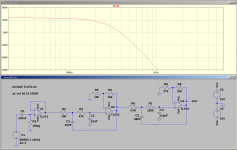
Looks good from here.View attachment 1033102
Am I loading and probing this correctly to display frequency response?

If you're using LTSpice, under Edit, Preferences, you can change the colour of the traces, background, et cetera. A thin dark blue line on a black background isn't exactly easy to see.
What happened to the power supply in the schematic? Is it off-screen to the right? (It's necessary for the simulation to work.)
-Gnobuddy
- Home
- Live Sound
- Instruments and Amps
- Instruments Amp Y4 trio