What players use the VAM1250
- By Kip
- Digital Source
- 34 Replies
I am interested in a cd player to use as a transport. I would like the player to have a VAM1250 transport. A unit with a VAM1202 would be ok too.


| THD+N (dB) | SNR (dB) | DR (dB) | Max Sample (kHz) | SE or Balanced | |
| PCM1808 | -93 | 99 | 99 | 96 | SE |
| ADAU1701 | -83 | 100 | SE | ||
| AD1938 | -94 | 107 | 107 | SE | |
| Cirrus Logic CS5343 | -92 | 98 | 98 | 96 | SE |
| AKM 5720 | -94 | 102 | 102 | SE | |
| PCM1802 | -96 | 105 | 105 | SE |

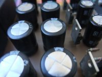
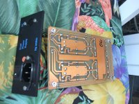


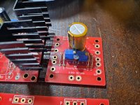


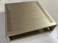

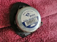
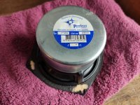
![PXL_20230508_182659685[1].jpg](/community/data/attachments/1080/1080220-66d1a7ac0fc3202ee705a9fe4ea93cd1.jpg?hash=ZtGnrA_DIC)
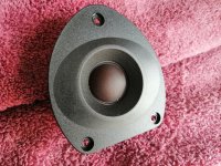
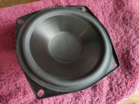
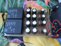
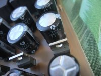
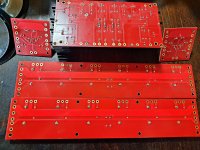
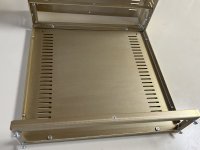
![PXL_20230508_182706822[1].jpg](/community/data/attachments/1080/1080221-d9da0beb47df4e2734e21c7429746e85.jpg?hash=2doL60ffTi)
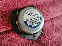
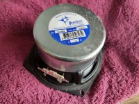
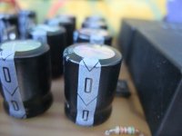
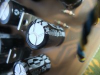
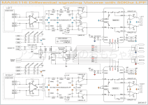
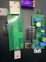
![PXL_20230508_182704670[1].jpg](/community/data/attachments/1080/1080222-d887c2afc8b77aea82ffdfc8ad873810.jpg?hash=2IfCr8i3eu)