If this review is supposed to be in a different section of this forum, please advise.
Introduction
As an avid audio enthusiast, I'm always on the lookout for equipment that strikes a balance between quality sound, versatility, seamless connectivity and pricing. Especially when it is ‘above average for value’. The Arylic B50 wireless stereo amplifier is a such a product that stands out on multiple fronts.
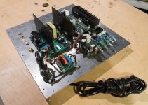
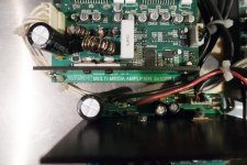
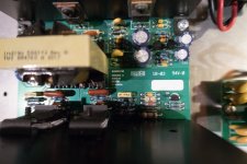
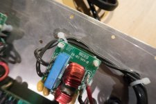
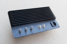
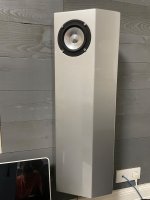
Design & Build Quality: The first thing that caught my eye was the sleek and modern design of the Arylic B50. Its compact size makes it suitable for various setups, blending effortlessly into any space. The build quality feels sturdy, ensuring durability without compromising its aesthetic appeal.
Connectivity: The B50 truly shines in its connectivity capabilities. Both wired inputs & outputs and wireless inputs & outputs, make the B50 extremely versatile.
Wired inputs:
- Phone IN
- Line IN: CDE player
- Optical IN (e.g. Xbox/PS4 or 5)
- TV via HDMI ARC
- USB
- DAC (for laptop or PC)
Wired outputs:
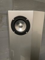
- Wired (passive) speakers for stereo
- Wired (active) subwoofer
Wireless input:
- Bluetooth (in receiver mode) for smartphone, tablet or PC
Wireless outputs:
- Bluetooth headphone
- Bluetooth speakers
Bluetooth transmitter mode: One of the standout features of the Arylic B50 is its Bluetooth capabilities for receiving audio, the ‘Bluetooth transmitter mode’, sets it apart. This mode allows the B50 to transform into a Bluetooth transmitter, enabling users to stream audio from the amplifier to:
- Bluetooth-enabled headphones, providing a personal listening experience without disturbing others in the room.
- A set of 2 Bluetooth speakers. So yes, it can even connect to two Bluetooth speakers for stereo!
aptX HD: The Bluetooth audio signal is supported by aptX HD and delivers high-definition (HD) sound quality wirelessly. This enhances audio transmission over Bluetooth with the transfer of 24-bit high-resolution audio files, which results in improved clarity, detail, and overall audio fidelity compared to standard Bluetooth codecs.
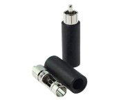
Phono In connection: A standout addition to the B50's connectivity options is the ‘Phono-IN’ connection. This dedicated input accommodates vinyl record players, allowing enthusiasts to directly connect their turntables without the need for external preamps. The inclusion of the Phono input caters specifically to vinyl aficionados, preserving the classic analog sound while seamlessly integrating it into a modern setup.
Sound performance: Where the B50 truly excels is in its sound performance. Delivering 50 watts per channel, this amplifier produces rich, clear sound with remarkable depth and detail. The audio quality remains consistent across various music genres, offering a well-balanced output that caters to both audio enthusiasts and casual listeners.
HDMI ARC Integration: What sets the Arylic B50 apart is its seamless integration with ARC technology. The ARC-enabled HDMI port establishes a two-way connection between the TV and the amplifier, enabling the transmission of audio signals from the TV to the amplifier without the need for extra cables. This integration simplifies setups, reducing cable clutter and ensuring a hassle-free audio experience for movies, shows, and gaming.
User-Friendly Interface: Setting up the Arylic B50 was a breeze. The intuitive interface and user-friendly app made the initial configuration effortless. The app's interface is clean and straightforward, providing easy control over settings, EQ adjustments, and source selection.
Value for Money: Considering its feature set and performance, the Arylic B50 offers excellent value for its price point. It competes admirably with higher-priced amplifiers while delivering a comparable audio experience and a plethora of connectivity options.
Conclusion: In summary, the Arylic B50 wireless stereo amplifier exceeds expectations, combining impressive sound quality, versatile connectivity options, and an intuitive user interface.
Especially the Bluetooth Transmitter mode is something special. As most Bluetooth devices are limited to be a Bluetooth receiver, the B50 can also transmit via Bluetooth. And it is even capable of transmitting to a pair of Bluetooth speakers to create Stereo!
Whether you're a music enthusiast or someone looking to elevate their audio setup, the B50 stands as a commendable choice, providing a seamless and enjoyable listening experience.
 FE48B280-F49B-4CD8-A1AC-7C70B9ADB07B.jpeg80.9 KB · Views: 484
 0440E13F-C9DE-4FEB-A390-8138835A1FD8.jpeg73.3 KB · Views: 371
 E3445584-C73D-4FC6-BCB4-B6E23E945E03.jpeg80.5 KB · Views: 285
 BF63F965-7C14-42F8-9114-52FBBD09766E.jpeg82.1 KB · Views: 315
 F7C49519-D965-415A-8365-35B19FFA8819.jpeg80.8 KB · Views: 272
 371F12B9-1B65-47F1-A08F-9C0CD87685AA.jpeg68.6 KB · Views: 285
 1A6D3011-103F-4C83-BAB0-5D4A95A208E9.jpeg71 KB · Views: 288
 41B117A9-0A03-47F1-AC6F-C7D2B8DC7021.jpeg78.4 KB · Views: 370