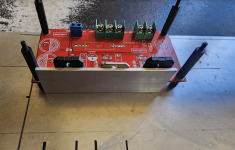
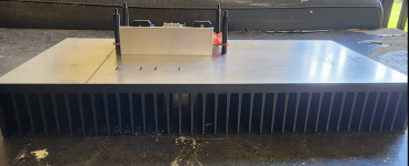
so I thinking of mounting the chips to the heatsink in this fashion (pics below and please ignore the spacers. those are there temporarily.)
The L-shaped aluminum bracket dimensions are 1.2in x 1.2in x 0.125in. i can also get (if these are better):
thoughts? Thanks in advance.
edit1: The bottom of the bracket will then be mounted to the heatink. (just stating this so it's clear)
edit2: The metallic thing with the black markings/lines is a 14in x 6in x 4in heatsink.


The L-shaped aluminum bracket dimensions are 1.2in x 1.2in x 0.125in. i can also get (if these are better):
- 2in x 1.2in x 0.125in
- 2in x 2in x 0.125in
thoughts? Thanks in advance.
edit1: The bottom of the bracket will then be mounted to the heatink. (just stating this so it's clear)
edit2: The metallic thing with the black markings/lines is a 14in x 6in x 4in heatsink.


Last edited:
If you mount the angled aluminium with the lip under the board, you will have problems mounting the assembly to your case.
I would use an extruded heatsink as it will be far more efficient in dissipating heat. Mount the fins upright for optimum air flow.
I would use an extruded heatsink as it will be far more efficient in dissipating heat. Mount the fins upright for optimum air flow.
@JonSnell Electronic
"you will have problems mounting the assembly to your case." any reason for this? I can install the L-bracket first and then install the PCB.
The L-brackets will be mounted on the heatsink parallel to the surface.
PS. I think I was unclear in my original post. The metalic thing with blank lines is a 14in x 6in x 4in heatsink.
What I personally don’t like here is the fact that in a parallel 3lm3886 amplifier 2 of the chips are TF and one is T version, while internally these are identical, the insulated ones/TF will have a bigger thermal resistance than the non insolated ones/T, I never tried this before , I don’t think it will work right.
And why would you install the chips before the passive components?
About your question, I think you should post a new picture showing the way you would like to install that L shape aluminum profile…
And why would you install the chips before the passive components?
About your question, I think you should post a new picture showing the way you would like to install that L shape aluminum profile…
@asuslover replaced the original pics which I'm hoping are pics that gives a better picture of what I'm trying to do. Thank you.
that's my 2nd option. just wondering if what I wanted is ok too. (space issues)mount the chips directly to the heatsink - no L bracket
It'll work just fine. As you point out, the die inside the chips is the same. Sure. The T version will run a micro-degree cooler. Big whoop. The main performance difference will be on the offset voltage, which is taken up by the ballast resistors. I don't see an issue with this as long as the metal-back LM3886T is fitted with the appropriate shoulder washer and thermal pad.What I personally don’t like here is the fact that in a parallel 3lm3886 amplifier 2 of the chips are TF and one is T version, while internally these are identical, the insulated ones/TF will have a bigger thermal resistance than the non insolated ones/T, I never tried this before , I don’t think it will work right.
I don't see an issue using the L-bracket to conduct the heat as long as it's somewhat beefy (say ≥3 mm in thickness).
Another option could be to machine a thick block that the ICs attach to and that's bolted to the heat sink.
Yet another option would be to make an angle bracket that holds the board onto the heat sink at a right angle so you can mount the ICs directly to the heat sink.
Tom
If you want to use L-shaped bracket is ok but you should use a bigger bracket so that the chips can be mounted on the bracket via thermal mounting kit and securely fastened to its surface.


- Home
- Amplifiers
- Chip Amps
- help with heatsink mounting