Looking for a starter diy project

Hey guys,


I am a student studying commercial music (this is my first post on this forum), and I am in a class where I need to do a diy project.


The project simply has 2 requirements:

-At least 75 soldering points, preferably thru-hole, as I am totally new to the realm of audio electronics and soldering.
-Obviously must produce or process sound


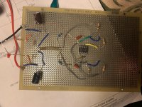
After doing a little bit of digging, I have started to like the idea of building a tube headphone amp. Know this is where you guys can possibly jump in and give me some advice, help, direction, etc.


I've found some simple kits on ebay/amazon/etsy (I'll link them below), but I'm wondering if y'all might have some links to other places for more ideas, or even other ideas for what I could potentially do with the simple requirements of the project. I'm looking for something ideally under $50. I'd like to be able to take this project a bit further in the future, and potentially make modifications to existing parts (i.e. adding higher quality matched tubes), because I don't just want this to be something I build and do nothing with.


I'd appreciate any advice/links on kits and making modifications that y'all can share!


Tube Amplifier AMP Audio Board Pre-Amp Mixer 6J1 Hifi Valve Headphone Diy Kit | eBay


https://www.ebay.com/itm/6J1-Valve-Pre-amp-Tube-PreAmplifier-Board-DIY-KIT-Headphone-Buffer-Case-AC-12V/332295637972?hash=item4d5e5d0bd4:m:mlER4ksGwR-dVHtU-YfgQJQ


Newest 6J1 tube preamp amplifier board Pre-amp Headphone amp 6J1 valve preamp | eBay


6J1 DC12V Valve Preamp Tube Board Headphone Amplifier Board+Acrylic Case DIY Kit 818692309840 | eBay

  • Poll Poll
6.5 inch v 8 inch drivers for 2 way speaker

What would you use

  • 5 inch driver

    Votes: 8 11.1%
  • 6.5 inch driver

    Votes: 32 44.4%
  • 8 inch driver

    Votes: 32 44.4%

I am thinking about a 2 way active speaker and looking for advice on the advantages and disadvantages of using a 6.5 inch v 8 inch driver for the mid range bass unit.

My understanding is that the 6.5 inch will be better for midrange and voice spectrum and not so good for bass whereas the 8 inch driver would be better on the bass but lose out on the midrange and voice.

Any advice and knowledge gratefully received

Thanks

Lee

Umbilicals

I am building a phono-stage with separate power supply. I was planning on twisting 3 14 gauge wires together for the 6.3V heaters x 4 and the same for the B+ voltage. I was going to pass that thru a few feet of insulation from some Canare 4s11 star-quad cable I'd remove the conductors from. It occurred to me that maybe the 4S11 in it's star-quad form might suit the bill just as it is for the B+ of 250V and the heaters. Thoughts?

Is it possible?

I was inquiring about a DIY preamp of commensurate quality to a Pass Labs and got a response from Wayne;

I would run a 250.5 balanced. The BA 2018 boards are done now in a dual version so it is easy to make a balanced pre.

I would still like to go this route and have a different question. I ran across a Pass Labs XP-20 at a price I could not refuse. I bought it thinking I could use it while I am building/perfecting the BA 2018 based preamp and could use it for comparison.

The question is, if I build an all out version of the BA 2018 based preamp could it equal or possibly surpass the XP-20?

By "all out" I mean separate power supply and best available components and build methods.

Passive radiator and relationship to driver

Hi guys,
.
I'm trying to use two of my PEERLESS 3.5inch passive radiators and getting confused when modelling. If I model some tiny speakers to let's say 80-90hz in a 0.01cuft box, would that mean the passive is the same tuning?

I noticed the FS changes if you add weight to the passive, but not sure if in Winisd the graph you see if for both or just the full range driver?

Removing large buss bars

I need to move three large buss bars out of my way to replace some predrivers on the motherboard. Are there any tips, tricks, watch outs, or work arounds that anyone wants to share with me before I dive in? I’ll be working on this tomorrow afternoon. The predrivers are located in the circled area in the picture.

Thanks,
David

Attachments

  • FD0A093D-83F5-49A5-8084-9F9703EA098F.jpeg
    FD0A093D-83F5-49A5-8084-9F9703EA098F.jpeg
    463.9 KB · Views: 96

Nelson Pass F-5 V3 outputs

Several years back I bought the F-5 V3.0 boards and now I’m finally getting around to work on them. I’m sure this comes up, but couldn’t find anything. What are the proper outputs for the V3.0? The FQA19N20 and it’s complement seem to be obsolete. I’m guessing there is a reason they swapped from the IRFP240 and it’s complement. I’m placing an order now, but not sure what to purchase. Any other parts that might be obsolete and need a replacement? I can’t seem to find a BOM for the V3.0.

Thank you,
Dan

Bypassing Volume Control

Picked up an Altec Lansing 944A power amp and am making it more friendly for home use.

I bypassed the input level controls by shorting the wiper to the input of the pot. Now the volume control does nothing but why is that actually the case?

If the pot is turned all the way down does that not short the signal to ground or to common? In the attached schematics, the input pot is R7. One is a closer up look at the input stage.

Also, the next stage is another op amp. Is that yet another stage of amplification or is it acting as a buffer? This boat anchor sure has a lot of drive and has a power transformer the size of a cantaloupe.

Any other suggestions to improve performance would be appreciated.

Attachments

Power transformers - Specs for max performance, core types and where to find them

I would like to get a discussion going over the common types of power transformers and how to extract the maximum performance from them. With the intention that anyone from the novice to the expert will know how to approach a winder with exactly what they need for a given performance level. To avoid snake oil, being overcharged, and to expand knowledge.

Areas I would like this conversation to go:

- Core types advantages & disadvantages, how to extract max performance from each
- Electrostatic screens for core types. Quantity and effectiveness
- Magnetic shields & effectiveness (Example: How effective on EI? Does an R, C, or UI core need one with balanced winding?)
- Winding for the core type? Balanced? Primary one one side and secondary on the other?
- Flux density for core types
- Temp. rise, how to specify
- Insulation MΩ, how to specify
- Ambient C°, how to specify
- Core material, grain oriented, M6 or Hi-B, Amorphous?
- Winders in the USA and abroad (especially if weak vs dollar)

FS: Troels Gravesen Quattro MKII ja8008hmq+tc35002 - Belgium

Due to tinnitus issues, I am stopping my diy audio hobby, I will keep 1 system.
I am selling off the rest of my stuff.

I am selling a pair of finished Troels Gravesen Quattro MKII (seas t35c002), sound great, look great.

Specs:
-crossover full superior z (includes 4 x 15uf superior zcap), wax coils
-JA8008 hmq woofer
-seas t35c002 tweeters + jantzen waveguides (routed for quattro)
-cabinet build in birch multiplex

I also have a pair of audax tw034 + jantzen waveguides (routed for quattro), these you get for free. The audax are recent, but the current (all of them) tw034 have a small fr deviation, they have a small dip at 6khz. Thats why you get them for free, they do sound ok. Because I wanted the best, I switched to seas t35c002.

At the moment I am not selling the parts yet, psychologically I am not ready yet to tear my speakers apart.

Price: 850€ (jantzen kit new price is 1660€, so this is a good deal)
Pickup only. I would not mind sending them, but they weigh 25kg/each and I dont have experience packing large speakers.

This is also an interesting deal for people planning to build tqwt/dqwt: also ja8008/t35 drivers, plus u can reuse the superior zcaps (or combine them with smaller values or mix in standard z).

ps I live in Gent, Belgium

Attachments

  • IMG_20191220_100916073.jpg
    IMG_20191220_100916073.jpg
    316.9 KB · Views: 397
  • IMG_20191220_101139457.jpg
    IMG_20191220_101139457.jpg
    803.1 KB · Views: 360
  • IMG_20191220_101123228.jpg
    IMG_20191220_101123228.jpg
    717.9 KB · Views: 346
  • IMG_20191102_113559000.jpg
    IMG_20191102_113559000.jpg
    839.3 KB · Views: 343
  • IMG_20191031_102602426.jpg
    IMG_20191031_102602426.jpg
    1,004.5 KB · Views: 333
  • IMG_20191202_205038671.jpg
    IMG_20191202_205038671.jpg
    688.1 KB · Views: 192

RIAA Equalization Standard...

The Riaa Standard deviation curve has specific and well defined poles. the 50Hz the 500 Hz and the 2122Hz...poles.

But then theres is some companies that seem to have their own version or interpretation of the Riaa curve..and by reading Thorsten response there seems to quite a bit difference...between these different riaa-curves...

Is there a place or a good resource where i can gather more info on this..???

near field vs far field mid woofer measurement

Hi

In my far field measurement is see a rise in amplitude at about 400hz. (attached)

The baffle dimensions are H:50cm; W:18cm.

if it is a baffle step, it is to late in frequency by 200hz according to the calculation.

F statr = (c/baffle width)/8

What do you think?
Driver: DSA135*8 5"
measurement distances are 1m and 20mm.
Pink is the near field. Orange if the far field.

Thanks
Ran

Attachments

  • Screenshot_2.png
    Screenshot_2.png
    99.6 KB · Views: 127
  • Screenshot_1.jpg
    Screenshot_1.jpg
    81.2 KB · Views: 119

Subwoofer amp

Hey comrades,

A few friends and I are building a sound system for small indoor events (genres will vary around dance music, lots of low end).
Just about too pick up some 4x p.audio c18-650el. And 2x mr2650 amplifiers.

Will probably build a g sub and a usb horn kick bin.

Obviously it isn’t ideal to run these speakers off these amps but we want this to be scaleable, so will will obviously move the amps to midrange as soon as we have enough money to buy some beefier amps but will it be fine if I really watch my levels.

We also have a really old studio master ax2500, c audio gb602 and a proel pl1300. Will the pl1300 run better on the low end at high enough power to drive the subs or will it cook my breakfast?

Crossover issue with my great 3 way DIY loudspeakers!

Hello everybody,

I need serious help as I bought a great pair of DIY loudspeakers.
Here are the pictures of the components and of the crossover:
DIY Loudspeakers Ben - Google Photos

Here is the measurment of the loudspeakers response :
Mesures.pptx - Google Drive

I have a small issue that doesn't help to listen in great condition : my medium and tweeter tend to the high frequencies.. The tonality is going a little bit too much on the high side rather than neutral.

Could you help me to modify the crossover in order to get the best out of my loudspeakers?

Many thanks in advance,
Benoît

Lookin' for good inexpensive open baffle FR options w/woofer assist

I'm playing with the Goldwood 1858s in the King-sized H-frames as a budget-bang config. I have them running with 3FE25s right now crossed over at 150Hz using the Parts Express/Sure DSP boards. The 3FE25s are pretty solid performers overall and certainly a good efficiency match for the 1858s, but at least in the OB they feel a little shouty and incoherent with some source material, particularly anything with distorted guitars.

I haven't done any measurements yet either but I feel like there's a hole in the lower midbass right around the Xover point which causes low-end pitch coherence to suffer a bit with busier, more modern mixes. (I am a trained musician and ADHD genre-hopper.)

Haven't done any playing with open baffle until now. Wondering what else is out there in the budget side that might speak just a little lower and do well on an OB without spending a bunch of bucks (not really interested in the high-end fullranger market, I want these to stay cheap). I have a couple TC9FDs on order for giggles - they will drop right into the cutouts for the 3FEs and I can use a $10 speaker for lots of other things - but I don't really expect them to be an improvement over the Faitals, especially since I'm pushing everything with small class D boards and they are a big drop in efficiency from the 3FEs.

...Could try 4FE32s too but they don't look like they'd sound or perform that differently from the 3FEs despite being a much prettier looking driver.

And also open to good ideas for possible 3-way budget OB "tops" / options for good cheap OB midranges. Doesn't have to be a single driver up there and the OB + DSP thing is really fun and easy to play with.

ADCOM 5500 weak bass: possible reasons?

Hey guys

I bought a second hand ADCOM GFA 5500 of unknown age. Upon hooking up the speakers I found the bass was too thin. On Nirvana's Smells Like Teen Spirit drum kick had nearly no impact. My a lot weaker integrated amp produces twice as much bass as the adcom which I was expected would be vice versa.

We're about to open the adcom and check the capacitors. Any other suggestions as to what to check?

Thanks!

Krell CD-DSP with Philips CDM1 Mk.II issue

Any suggestions on what might cause this cdp to not be able to read a disc until it has warmed up for like an hour? The case must be warm to the touch before it will return something other than disc error. I've checked all the board and transport connections and have gone over the PCB's looking for cold solder joints. This thing must be built to MIL-SPEC, very impressive indeed.

Problems with BBB-Hermes-Cronus for Buffalo-IIIsePro38 build.

Hello everyone.

I have problems to get my BBB-Hermes-Cronus-Buffalo-IIIsePro38 build to work. I already asked this question throughout different official TP threads, but I think it is just confusing to post in these different threads, so I opened a new one just dealing with my problem with the hope to finally get it working 🙂. So, here we go...

The Buffalo does actually work with an external SPDIF signal fed in through the "GND" and "SPDIF" connectors and the Buffalo switch 1, position 1 to "ON" for SPDIF input. Then the "LOCK" LED lights up and I can listen to music.

Hence, the problem must lay in the BBB-Hermes-Cronus combo producing a PCM signal (for which I move the above switch to "OFF" for SERIAL(PCM/DSD) input. On the BBB I run the prepared Debian distro including Botic by twluke: https://www.diyaudio.com/forums/twisted-pear/258254-support-botic-linux-driver-258.html#post5515941. Below are the outputs of some important commands:

debian@arm:~$ aplay -l
**** List of PLAYBACK Hardware Devices ****
card 0: Botic [Botic], device 0: external botic-hifi-0 []
Subdevices: 1/1
Subdevice #0: subdevice #0

debian@arm:~$ aplay -L
null
Discard all samples (playback) or generate zero samples (capture)
default:CARD=Botic
Botic,
Default Audio Device
sysdefault:CARD=Botic
Botic,
Default Audio Device
dmix:CARD=Botic,DEV=0
Botic,
Direct sample mixing device
dsnoop:CARD=Botic,DEV=0
Botic,
Direct sample snooping device
hw:CARD=Botic,DEV=0
Botic,
Direct hardware device without any conversions
plughw:CARD=Botic,DEV=0
Botic,
Hardware device with all software conversions

debian@arm:~$ speaker-test

speaker-test 1.1.3

Playback device is default
Stream parameters are 48000Hz, S16_LE, 1 channels
Using 16 octaves of pink noise
Rate set to 48000Hz (requested 48000Hz)
Buffer size range from 16 to 786432
Period size range from 8 to 393216
Using max buffer size 786432
Periods = 4
was set period_size = 196608
was set buffer_size = 786432
0 - Front Left
Time per period = 10.378743
0 - Front Left
Time per period = 10.239861
0 - Front Left
Time per period = 10.239897
0 - Front Left
Time per period = 10.239885
0 - Front Left
Time per period = 10.239877
0 - Front Left
Time per period = 10.239869
0 - Front Left
Time per period = 10.239883
0 - Front Left
Time per period = 10.239875
Q1: Someone said that the output of speaker-test indicates that the BBB recognizes the clocks on the Cronus. Which signals does that include exactly and which one could still be problematic?

While letting speaker-test run I could not identify an output signal with a multimeter set to mV and AC. At the input header I could only detect a signal of 1,6V AC at pin 9 for the "MCK_IN", but not for "DCK_OUT", "D1_OUT", or "D2_OUT" (see attached picture). Also of 3,4V DC at pin 10 and 20.

Q2: Shouldn't I measure a signal at the inputs for "DCK_OUT", "D1_OUT", or "D2_OUT"?

Q3: What could be the reason for just getting a signal at "MCK_IN"?

Q4: Is there any measurement I could do for finding the problem?


As always I attached some picture in the hope that someone spots a stupid mistake 🙂. Thank you very much for your help!

Attachments

  • image10.png
    image10.png
    6 KB · Views: 528
  • IMG_20181019_195045.jpg
    IMG_20181019_195045.jpg
    1,007.9 KB · Views: 527
  • IMG_20181019_195058.jpg
    IMG_20181019_195058.jpg
    1,002.8 KB · Views: 521
  • IMG_20181019_195108.jpg
    IMG_20181019_195108.jpg
    998.7 KB · Views: 500

Prevent too much high voltage

My power supply (with 30 seconds delay and NTC inrush protection) is reaching max. voltage before the amplifier's power tubes start conducting.

In order to prevent the tubes to get too much voltage (my limit is 600 Volts), I created a shunt today using zener diodes and a high power mosfet.

This basic circuit has been tested and is working. When the voltage is just below 600 Volts (when power tubes are conducting), no current flows throught the shunt circuitry.

I'm still not sure how to share the dissipated power for voltages above 600 Volt; part is dissipated in the mosfet, part in the drain resistor. The mosfet can handle more than 200 Watts and the resistor can take 50 Watt. Fortunately the periode of power dissipation is approx. 90 seconds.

NB: I didn't choose for a series voltage regulator due to the voltage loss caused by the regulator.

Of course I will keep testing and improving. Any comments and help are welcome.

Regards, Gerrit

Attachments

  • Shunt-Overspanningsbeveiliging.png
    Shunt-Overspanningsbeveiliging.png
    19.6 KB · Views: 289

Ikea Eneby 30 DSP programming - TAS5731M - TAS5711

Hi everyone!


I want to program the DSP chip inside the Eneby 30 speaker from ikea which has a TAS5711 and TAS5731M, but i dont know how to do it. I never worked with a I2C protocol before so this is totally new to me.. I dont know what kind of programmer and software i need for this, but i did already contacted TI for using their PurePath software eventhought i am not sure if this is actually the software i need 😉 Can anyone help me with this?

Thanks!

Help me to decide between these whizzer designs

I have two old 2-way enclosures that I had to rebuild.

While rebuilding the woofers, I chose to use a whizzer to get some more mid-range, and I did something similar to design 1 of the picture below, using silicone sealant for the larger cone and epoxi for the whizzer.

However, the result wasn't exactly what I expected. I don't have the equipment to measure the output, but there's an audible dip between 1.5 and 3.5 kHz. And it isn't as loud as I expected as a whole.

And then I thought of a second possible design (number 2 in the picture), using two cones inside each other, the smaller one being made of a lighter material (and directly glued to the voice coil) and being connected to the larger and heavier cone by a stiff corrugated surround.

What do you think?

One of my concerns is that smaller the cone I currently have (which came from a 5 W speaker) seems too weak and might be teared apart by the voice coil. The other concern is with nonlinearity of the inner surround, as it could be too much stretched.

But I can't quite imagine how the frequency response would be or if it would have any advantage over design 1.

What do you think?

C3B5Zqx.png

Speaker query, Jaguar X300 restoration, Harmon Kardon

Hi all,

I own a 1996 Jaguar X300 XJR with the Harmon Kardon uprated audio pack. THis was an £800 option when the car was new, and instead of using the ISO speaker outputs, it takes a signal from the preamp port of the original Alpine AJ9500R head unit, to a Harmon Kardon amp in the boot, and then routes wiring to a series of Harmon Kardon speakers throughout the car.

There are speakers (I think 6", but checking) in all four doors, plus tweeters in the A pillars and the rear doors, plus a 6x9" dual voice coil subwoofer in the parcel shelf.


The foam has deteriorated completely on the 6x9, and there were holes in the cone. These speakers are very expensive secondhand, given that they're DVC and shallow. You can't get a deeper speaker in the hole as it would foul the fuel tank, so originals are in demand. I'm attempting a repair on the basis I can't make it any more broken than it was, and that I could save myself an expensive bill. I have repaired the holes using tissue, and intend to replace the foam around the cone.

While I'm at it, on the logic that they're all the same age, I'll be replacing the foam on the 6" door speakers too. A couple of them sound flat, so it's probably about time for them to be done.

I appear to have a choice of foam or rubber surrounds for 6" speakers. I'm led to believe that both will offer different sound qualities, but that rubber will last longer.

Would I be better to replace like with like, or to choose rubber for longevity? If the climate matters, I live in the UK.

Thanks for your advice!

Xelex DD-8

Does anyone know anything about this amp? I bought it recently on a Swedish auction site, and my original thinking was that if it was not functional, then I could repurpose the case for a tube amp.

It was missing the cap on the fuse holder, so I replaced the holder and fired it up with a variac, and I had sound from one channel. I do not have the right input plugs so I had used wires into the holes, so maybe I had not made a good connection. I will check again.

The channel that was working was OK - not spectacular, but difficult to judge when it is just one half the stereo signal.

It would be good to know if I should be treating this as an object that ought to be repaired and passed on to someone who would value it, or treated as a run-of-the-mill PA amp from the 70's, that is fair game to be re-purposed.

Attachments

  • IMG_1723.JPG
    IMG_1723.JPG
    394 KB · Views: 413
  • IMG_1721.JPG
    IMG_1721.JPG
    197.4 KB · Views: 430
  • IMG_1720.JPG
    IMG_1720.JPG
    814.4 KB · Views: 442
  • IMG_1719.jpg
    IMG_1719.jpg
    351.8 KB · Views: 423
  • specs pg2.jpg
    specs pg2.jpg
    122.4 KB · Views: 434

Guides / projects for this New York neophyte?

Hello everyone. I'm ready to take the plunge and teach myself electronics / amplifier design. In college I majored in humanities, but aced two semesters of physics to fulfill the science curriculum requirements. It's been some time since I've done serious math, so I'm looking for advice on a refresher course in trigonometry along with a course to learn the fundamental maths needed to understand electronics. Next, it would be nice to have a guide to walk me through rudimentary circuit designs culminating in building basic class A and A/B amplifiers. My long term goal is to understand the latest class D technologies, but I've got a long way to go before thinking about that. I'm burned out on the humanities, so depending on how far I can get teaching myself, I may end up going back for a new degree. Thank you!

Hey y'all, Long time reader first time member from new south Wales Australia

Hey guys and girls, firstly thank you one and all for all of the valuable information I've already received from this community it's been a big help. I've recently found myself back in the world of diy audio after a few years, However this time around my goals are far more simple widely researched and covered, I'm just having a bit of trouble getting all my ducks in a row so to speak.

I am building speaker cabinets for instruments (both for myself and others) , bass, keys and guitar, however it is the 'full range' for bass and keys that are providing the most painful calculations.

So with that said, this is the first step on an adventure, if anyone could point me in the appropriate direction to post questions about crossovers and filters, that would be most welcome. Thanks again and, I'll see you at camp.

FS: Prebuilt Bigbottle MM/MC phonostage PCB

Hi All,

I built this to get it tested prior to the GB that's currently gathering pace.

I wanted to make sure everything was ok after having the layout redone by our very own Craigtone.

All the caps in the signal path are Vishay (2x wima as I had them) and they are matched for exact values, as are the resistors. The two green caps are my "must have" from the capacitor world and were extra cost. I will leave them in for the sale.

Everything has gone as expected (never in doubt) and I have no use of this PCB as I have a fully functioning Bigbottle phonostage currently playing!

All that's required is a suitable case, transformer and some valves and you are good to go.

Transformer can be had from Audiophonics.fr, for around €30 but be prepared to wait for 2 months for it to arrive lol.

2x PCC88's and 1x ECC85, A case for about £50-70 and other than a few rca sockets etc, you could have this up and running for around £400 total.

Which for a valve phonostage of this quality, is super cheap.

I'd like to get as close to £200 for it as possible. That's about what I have spent on it.

Postage in the UK is likely to be about £10, EU £15 and the USA about £20

If I'm offered the asking price I'll do free shipping. Nice aren't I 😉


20200227_183051.jpg20200227_183053.jpg20200227_183056.jpg20200227_183100.jpg20200227_183104.jpg

Morel 2-Way Design

I have a Morel CAW 538 and CAT 378 I am trying to design into a 2-way bookshelf in a 7L bass-reflex enclosure tuned to around 42Hz. I know if I flush mount the tweeter and surface mount the woofer I will have near perfect time alignment. It is coming down to the crossover and I wanted to bounce a few ideas off the forum because I see two strategies.

First strategy is to do a simple 2nd Order LR Filter at 2500Hz with an L-Pad on the tweeter and call it a day.

Second strategy is a little more ambitious, but I think may yield a better result and take advantage of the excellent FR of these drivers. I think I can get away with a Dynaco A25-esque design. The woofer has a nice rolloff starting around 4000Hz with a small peak around 8000Hz (cone breakup?). My idea would be to address this with a 1st-order filter around 5-6kHz to make sure it is far enough down it will be inaudible with a simple 0.5mH coil (impedance is about 13 ohm at this frequency). Then use a 1st order on the tweeter around 7000Hz. I say 7000Hz and not 4000Hz because the tweeter has a subtle rise (going backwards towards the crossover point) from 6000Hz-3000Hz that could be nullified by the gentle slope of a 1st order crossover. I would likely use 2.2uF cap. Am I crazy or would something like this work and give better transients?

Background: I have been building DIY speakers for a few years now. I know my way around a schematic, am handy with a soldering iron, and now feel ready to cut my teeth with a design of my own.

Philips VTVM 6058 pristine (in risk of being scrapped if not sold)

two Philips Holland SQ E80F (substitute EF86) and one EZ80

I'm stripping a Philips GM6058 VTVM as it is too heavy to ship to other parts of the world and no interest locally.

The unit was fully functional and looked like it had been hardly used.

I've listed the tubes on the famous website in the UK, make me an offer there.

If you want any other part let me know but I am keeping the knobs, the tube sockets and the binding posts. Everything else can go.

Thanks!

edit: no longer available, disassembled and tubes sold.

TDA8932 has problems with 4S BMS

I use one of those tiny TDA8932 boards to amp an fr-br-box.
Auswahl_026.png
The amp sits inside the cabinet together with analog preamp i built around an TL074.
That preamp offers a mono-summer and tone controls.
Everything worked like a charme .... but then i had an idea....
Yesterday i built a battery-holder with four 18650 cells into the cabinet.
I glued an bms-pcb to the backside of the battery-holder and connected everything as shown in the pic.
Auswahl_025.jpg
LOAD are the amp and preamp in parallel, CHARGER is the DC-jack that i already had at the backplate of the cabinet, only thing that is not shown is a switch that (dis)connects the LOAD from the plus-line.
I attached precharged cells and measured 16.5V.
As soon as the LOAD is connected the voltage drops to about 300mV.
That's still the case, when the preamp is disconnected.
And now the crazyness starts:
I plug 18V DC to the CHARGER inputs.
The amps starts playing (quite noisy).
I disconnect the DC plug.
The amp keeps playing from the batteries - now very nicely, because almost noise free.

I don't accept the emergency-start with the DC plug as a solution.
Please help me explain the nature of the problem.
Please help me find a better solution.

DIY Voice Coil with Cone

Hello forum members,

Are there any online calculators or is there a mathematical formula that can be used to calculate the target impedance of the voice coil based on the gauge of the wiring, the number of winds etc?

For example, if my initial target is an 8 ohm voice coil and I am using 38AWG wiring, what would the optimal method be for determining the number of winds to get to an 8 ohm voice coil? I have a standard LCR meter and a high precision LCR meter as well, I had thought about periodically melting the wire during the winding process to measure the inductance/capacitance/resistance of the coil on the jig to derive a formula for the length of wiring/number of winds needed, but that's probably not the right approach nor do I think it would work based on the wire still being attached to the spool feeding the winding jig.

I am also curious about how the number of winds affects the magnetic field collapse. I am sure these are basic electronics 101 questions but I can't find any direct answers from the research I've done so far.

Thanks in advance for any input!
🙂

2019 Honda Clarity Hi-Fi Project

This is a think-out-loud post. I've never worked on a car stereo so I'm not sure how to approach a system build.

2019 Honda Clarity. I want to improve hi-fi quality of system at lower volume listening levels. In my home I listen at about 75db. Peaceful car commute styles of music.

I pulled the door speakers and tweeters to take a look. Door speakers are built into a plastic frame. They're light so must have a tiny magnet. Tweeters are located in the A-pillar and in the rear door panel.

The vehicle has active noise cancelling with two microphones inside the car. The Honda Clarity is an EV so they lightweight everything. I think the ANC is to reduce road noise without adding weight.

I'm not sure how to approach this because I don't know how the car audio environment works. For example, do cars bother with stereo separation or does mono sound just as good? In home audio you can have a center seating position. But since you can't do that in a car is it just as good to play all your music in mono channel?

Do good car systems try to place the speakers as close as possible to the head for near field listening or is the environment so small that all speakers are effectively near field?

I need to find some articles to help me figure out how to think like a car audio system designer.

Attachments

  • IMG_20200226_124119325.jpg
    IMG_20200226_124119325.jpg
    377.4 KB · Views: 130
  • IMG_20200226_125104070.jpg
    IMG_20200226_125104070.jpg
    161.1 KB · Views: 123
  • Annotation 2020-02-26 125812.png
    Annotation 2020-02-26 125812.png
    389.4 KB · Views: 139
  • Annotation 2020-02-26 125841.png
    Annotation 2020-02-26 125841.png
    446.5 KB · Views: 135
  • Annotation 2020-02-26 125917.png
    Annotation 2020-02-26 125917.png
    371.8 KB · Views: 128

Sure DSP ADAU1701 board with amplifier JAB3-50

Hello everyone
I already asked in the profile branch, but I did not receive any answers, then within 2 weeks I looked for information on the Internet, but I did not find the answers to my questions and therefore I created a topic in the hope that someone will see and answer


Within my project I have to create amplified subwoofer (40-200 Hz and max volume 3 L). I know that this is a challenge to reach this parameters, but I would like to discuss just electronics part.

I found JAB3-50 Audio Amplifer with DSP. I am really interesting in this solution, but I need to clarify some practicals aspects of this solution. Since I have limited budget it is very iportant for me to know all aspects, because Sure web site does not provide full info. Also I have contacted to Sure via mail, But I recieved answer from manager (...you know)

So, could you, please, answer and clarify some information:

1) To get 2.1 (I need to connect mu sub to the other passive 2 channel sustem) I need to use JAB2 & JAB3, but in this case does it work like whole system, I mean if I want to use Bluetooth connection will I have output sound from both JAB2 & JAB3 (Bluetooth will work for these two boards). In general, bluetooth connection is good?

2) In case of using input audio via cables (not Bluetooth) where I have to connect my input signal to the JAB2 board? or JAB3? I did not find this information

3) In case of using JAB2 & JAB3, if I understood correctly, DSP on JAB3 provide 4 output channels? So in Sigma Studio can I use 2 channels from JAB2 and 2 from JAB3?

4) Can I use many filters in Sigma studio and what are the limitations for this DSP ( I mean how many filters or types of filters or memory and so on...) ?
How many instructions I can use with ADAU1701?

Because I have ADAU1772 evaluation board (for a test) and inside Sigma studio there are just 32 instructions and limited toolbox for the dsp

5) If someone had the problem, when this two board are in idling regime (without input signal) there are some noise? Because I have seen some video on YouTube, when this problem was take a place ( YouTube )

6) If I want JAB3 only for subwoofer channel I have to connect two output channels in one channel, in this case all parameters for this 2 channels in sigma studio should be identical? is not it?

7) To provide DSP without Sigma studio, In-Circuit Programmer- ICP1 should be connected all the time to JAB2 & JAB3?

8) If I choose bluetooth regime on ICP1, all DSP settings are disabled?

Because it would be great just to control the volume from the Sure app from smartphone and using self-boot EEPROM. Or this is not possible?

9) What about the problem of 12 MHz crystal. Is the problem fixed? now all boards are 12.228 MHz crystal?
But what is critically to use the board with 12 MHz crystal?

10) Are there any other bugs and is this solution generally good?

What about amplifiers of this board? Are they implemented well? will they work with 2 Ohm load?

Sorry for the big questions.But I really hope for answers and I will be very grateful

Thank you so much!

Help with first build (cmoy)

I’m attempting my first build of an amp. I am doing this to learn. I am using the cmoy design. The power supply tests fine (4.8v and -4.8v) and the light turns on but no sound. I’m not always using optimal parts but was hoping I could make it work. What did I do wrong?

Attachments

  • C2A4AD61-C38F-48F0-9DEC-C2B53925C1E9.jpg
    C2A4AD61-C38F-48F0-9DEC-C2B53925C1E9.jpg
    1 MB · Views: 161
  • E262FD1E-10F7-4B02-9AFC-A2E760F1F8E9.jpg
    E262FD1E-10F7-4B02-9AFC-A2E760F1F8E9.jpg
    1 MB · Views: 149

Digital Coaxial Cable Length Question

I would like to replace the generic Toslink cable running between my streamer and DAC with a digital coax. I have 1m of Furutech Alpha Ag-75 cable and some Good quality RCA connectors (BNC not an option on my gear) to work with; however, I have read several places that digital coax cables should be a minimum of 1.5m to avoid signal reflections, timing issues. (Some have added that a very short length - under 1 ft - would also ameliorate such problems.)

Should I be worried about the length of the cable? Would I be better off constructing a short, < 1 ft. cable vs a 1m cable? Do I need to reconsider materials entirely?

Thanks for any guidance before I start.

Paul

How to measure DC offset on the mains voltage?

DISCLAIMER: Please be advised that the following content in this thread is revolving around mains voltages which can be lethal, read the content in the link as follow before proceeding.
>>> https://www.diyaudio.com/forums/tubes-valves/announcements.html <<<

****************************************************************************************************


I come to think of the DC offset on the mains voltage and that a relatively small DC offset can easily make transformers upset and make louder humming, so I thought this sounds like a trivial task to find out with perhaps ones multimeter and so started to search the internet for an answer on how to do it, but it seems to be not that trivial after all.

I tried to measure the DC voltage with my multimeter set on 1000V but it didn't show anything, maybe either due to no DC offset present and/or my old multimeter isn't sensitive enough, and the next lower step on the multimeter is 200V which I don't dare to try as we have 230VAC mains voltage. While searching the internet I came across some text mentioning some multimeters can measure true RMS VAC with a DC offset, but it appears to be just a sum of both DC and AC (True RMS ac + dc =SQRT( ac^2 + dc^2)), so, how can one in the easiest pragmatical way determine (measure) the DC offset value on the VAC mains?


Tip 2: Measuring an AC Signal with a DC Offset | Keysight (formerly Agilent’s Electronic Measurement)
AC Measurements Using the Oscilloscope and Multimeter by Mr. David Fritz - PDF Free Download
Mains DC and Transformers

FS: Open Baffle Drivers and Crossover for PAP Trio15 TB

I have the following in like new condition for anyone interested:

4 - PAP 15" Woofers
2 - Tang Band W8-1808
2 - Crossovers which include Jantzen C-Coil 4.7mH, Jantzen Alumen Z-Cap 10 uF, and Clarity Cap CSA 68uF​

See attached photos of my prototype.

The combination sounds amazing but WAF is non-existent so I have been ordered to get rid of it all. My total cost of these parts is over $1900 but I am willing to entertain any reasonable offer.

Attachments

  • IMG_5544.jpg
    IMG_5544.jpg
    1,013.6 KB · Views: 525
  • IMG_5545.jpg
    IMG_5545.jpg
    994.9 KB · Views: 515

Hafler DH-101 Preamp

I know this is an old question about an old preamp - but I could use some help. My son just came back from "dumpster diving" and came up with an early model Hafler DH-101 preamp - serial # 1108025. I once own such a beast and performed a number of modifications upon it back in the 80's. However, I have forgotten everything!!

Here are my questions:

1) What did Hafler's DH-106 modification kit for the DH-101 consist of? Wasn't it related to swapping out transistors?? Do you recall the part numbers and what was swapped for what?

2) TMy son's unit has transistors with numbers like MPS13, MPS63, BC559, BC549c, BC415 and BC414. However, I tracked down a manual/schematic from Rockford's Hafler site (for a unit w/ serial # 1812829), and the parts list for the unit shows transistor numbers ALL starting with "MPS-A", like MPS-A-13, 18 and 6523. Which unit (mine or the 1812829 unit) has the updated transistors??

Any help is appreciated!!

Pete Snyder

EI Power Transformer - Dual electrostatic screen winding grounding help

I am considering an EI type power transformer with two electrostatic screens between primary and secondary. Similar to how this: VinylSavor: Power Transformers

"The first one,which is closer to the primary is directy connected to the core, which should have an electrical connection to the chassis and thus to mains earth. The second screen is meant to be connected to signal ground. This provides an even improved isolation from mains noise."

I plan to have one built to my specifications however I realized that I know very little about grounding. I am building the DCPP mono tube amp which originally used the Hammond 290FX power transformer (https://www.hammfg.com/files/parts/pdf/290FX.pdf) with the 0V being the ground connected to the PCB.

So if this new transformer has two grounds instead of the one that the Hammond 290FX has how do I ground this amplifier properly? Engineer's amp 50W monoblock

Soundstream USA 305 Schematic or Equivalent

I have a Soundstream USA 305 that has a short burning up R208 (10 ohms, blue resistor bottom edge of the board) that is connected to the transformer secondary common routing to multiple transformer common connections.
All 6 cards are removed. All TIP's are removed.
I can not read any voltage or current numbers across the resistor as it heats up instantly.
If I remove the LM7815 and the LM7915 the resistor seems to be fine so I am looking to see what the 15v circuit consists of.
Will the resistor current be higher than a short in an Op-Amp assuming the 15v only contains the Op-Amps.
Does anyone have a schematic or a comparable schematic of the USA 305?
Thank you all!

Attachments

  • DSC_0071.JPG
    DSC_0071.JPG
    794.6 KB · Views: 118

2 way vented box. which driver ?

Hello!

Anyone got experience with the Beyma 8G40 and/or the Beyma 8WR300 ?

I would like to build a 2 way vented box using it as a stereo top for a subwoofer. My goal is to achieve to get as low as about 70-80 Hz ish (not at 0 dB of course) up to 2k Hz. To a get a presence and to support the sub upper 70-80-90 freqs with the top speakers. Which one is more suitable ? I haven't found any opinions about them. https://www.beyma.com/speakers/Fich...akers-data-sheet-low-mid-frequency-8WR300.pdf
https://www.beyma.com/speakers/Fichas_Tecnicas/beyma-speakers-data-sheet-low-mid-frequency-8G40.pdf

FS: Lambda reg tube PS

Lambda Model 28 Regulated tube power supply. Rated Max 300Vdc 100mA and 6.3 Vac 5A.

Just serviced and tested.

Tubes checked.

All wires checked, and re-sleeved or replaced as required.

All resistors checked and replaced as required.

Circuit mods to lower noise from 5mV to uV range.

CLC caps replaced: First cap increased to 10uF oil (was 4uF) and cap after L increased to 75uf (2 x 150uF HF electrolytics) and bypassed with ploypro.

Output cap replaced with SCR 30uF polypro (was 2uf).

Multi component chassis ground decoupling circuit added with ability to connect or dis-connect from HV -DC (original output floated from chassis ground).

6.3Vac output converted to DC with 25A bridge rectifier and 10KuF cap (you add dropping resistor and cap to reduce to 6.3Vdc per your circuit amp need).

This is a great vintage regulated tube power supply from a respected company and highly sought after.

Asking $200 plus ground shipping (unit is heavy).

Attachments

  • Crop1.jpg
    Crop1.jpg
    405.5 KB · Views: 617
  • DSCF2324.jpg
    DSCF2324.jpg
    645.7 KB · Views: 603
  • Rear Crop 1.jpg
    Rear Crop 1.jpg
    787.2 KB · Views: 608
  • TermView.jpg
    TermView.jpg
    895.9 KB · Views: 595

Classic RCA phono/passive linestage preamp

RCA Classic tube phono stage with passive line stage. Modern hybrid design of the Classic RCA phono stage with MosFet follower output. Passive RIAA eq. Tubes are new 6n4 low noise.

Each channel has LR8 HV regulator . Power supply uses Schotky rectifiers. Tube heater is regulated.

Passive line stage. Output has mono 100K ohm volume controls. Gold input and output RCA connectors. Built with many new HQ parts.

Will ship with circuit schematic.

Buyer pays shipping.

Asking $250.00

Attachments

  • DSCF2514.jpg
    DSCF2514.jpg
    445.3 KB · Views: 593
  • DSCF2513.jpg
    DSCF2513.jpg
    668.9 KB · Views: 596

SE Output xfmrs....who are the current suppliers for not many $$$

Hi all,

It's been 15 years since I last saw a thread on low priced, or reasonably priced output transformers, the last thread was great but some of the mfrs are gone, part numbers have changed etc.

I have decided to build a single ended tube amp, not sure which output tube yet but I have lots to choose from in stock. Under consideration are 2A3, 211, (242C, 276A, 261A all same size as 211). I would also consider 300B but would have to buy those, I have all the others I listed.

I have been looking around and re-reading the old thread and have found Edcor and Transcendar are still in business, James seems to be gone and some of the others mentioned are getting hard to find. Hammond is still going strong as well and I can get locally as they are a Canadian company.

So what is currently a decent quality SE output xfmr, either Asian or North American? Not looking for specific part numbers, more of a survey of current suppliers. Also don't want to buy the old classic megabuck partridges etc. I see on epay for a kilobuck per pair. Would be nice to find good ones less than $100 ea.

My other thought is to find an inexpensive already built amp with one of the listed tubes, then mod the crap out of it, or gut it and put in my own circuit and use the chassis and xfmrs etc.

Look forward to hearing your recommendations and if you have used them, your opinions of sound quality.

Cheers

24 volt smps conversion to split output +24 / -24 volts

Hi I am building a class-a six channel amp and want to convert a 1000va single output 24volt power supply to split output IE +24v / -24v.
I have searched around and there are a few tutorials for low power applications, but found one on utube which may be suitable for high power. I will be using heftier diodes.
What do you think


YouTube

Sanity check on compression drivers for 811B horns

Hello everyone.

First and foremost I want to say that I have no clue what I am doing, so if I say something stupid, please be patient 😛

I recently acquired some 811b horns and I am looking for a decent driver to pair with them. I have done some research on different drivers that would work well with them but most of the recommend drivers seem to be out of production (BMS 4550) or very expensive (faital pro).

I found these PVR drivers that are cheap, but they seem to be far from ideal https://www.parts-express.com/pedocs/specs/294-2833--prv-audio-d290py-b-specifications.pdf

Do you guys think the PVR drivers are worth a shot? Or are there better drivers out there that you guys can recommend for 200 a pair.

MiniDSP 8x8 in 1U Rack Enclosure

Hi all!

I wonder if anyone might be able to answer what might be a couple of daft questions about putting my 8x8 in a metal rack case.

My 8x8 has been sat on my shelf working for a year now and I've had issues with noise from my computer getting through to the audio. I hear discs spinning up and a ground loop whine. I thought the next step in solving this problem is to case up the MiniDSP and eliminate potential causes one by one. So...


1. When I mount the board to the case do I want to use metal hardware to couple the board to the metal for shielding?


2. If I do the above can I mount the DC power socket straight in to the metal without isolating it?


3. Are there any recommended things I should do in the process of what is seemingly a simple mounting?


This is the case I have ordered:
https://cpc.farnell.com/penn-elcom/...1u-220mm-deep/dp/EN55271?MER=sy-me-pd-mi-alte


Cheers! 🙂


http://www.minidsp.com/images/documents/miniDSP 10x10 Hd and 8x8 kit User Manual.pdf

Problems with VAS current limiting

Hi, here is the schematic on test:

9byidBF.png


EDIT: I corrected the schematic

I omitted the output stage because of space, and because it is not really important to know so much about it: it's only a classic emitter-follower output.


Straight to the problem: distortions created by VAS current limiter. The transistors are Q15 and Q18.


That is strange because this should not affect the VAS, current limiting should only guarantee a static current and not create distortions. Yet it seems that with the spectrum analyzer (in the real model) its presence and absence make the difference between having so much distortion and having little.

I'll explain:
- Raising the biasing current, the situation does not change.
- Both with and without the current limiter on the VAS, transistors Q14 and Q16 always have 5.5mA of through current.
- By changing the output stage, changing it in many different ways, the situation does not change.
- No load, no distortion register at the amplifier output. But with even 8 ohms of load, and high output transistor polarization, if the current limiters are present, the distortion is 0.85%, while without them it is 0.01%.


You say: if the current is the same with and without, why not simply removing it?
I say: the current passing is highly variable based on the beta of the transistor, and also because the current varies greatly based on the increase in temperature.


What I have done wrong in this configuration?

Generating an auxilliary negative rail from DC rails

Hi Folks,

I want to generate an auxilliary negative rail of -60 volts inside of a power amplifier for some biasing experiments that I want to carry out. The problem is that the main +/- 40 volts rails are generated and smoothed in a seperate unit and I don't want to modify that, so I need to generate it from one of the existing D.C. rails and in the power amp case. I don't need a lot of current, 5 to 10mA at mos,t and referenced to the same 0 Volt line as the main rails so it sits 20 volts below the negative rail.

The best way I have come accross so far is to pad down the + 40 to about 15 volts or so and use that to power a 555 timer running as an oscillator and then use a charge pump/ x4 voltage muliplier/inverter on the output to get down to - 60 volts or so. I could then use a zener or shunt regulator to stabilise it.

Buck/boost regulators don't seem to have the capability of getting down to -60 Volts.

Does anyone have any other ideas or better ways to do it?

Thanks and regards

Mike

1969 Selmer PA head with stock Mullard EL34s & Ecc83s: What would you do with it?

I just bought a stock 1969 Selmer TV 100 MKII PA head in original condition including four original Mullard Xf2 EL34s and ECC83 (UK factory)!

The amp is in full working condition (one channel has some noise, I suspect a failing preamp tube) and I will start cleaning and testing it soon.

Since it is not a real beauty or of historic value (?) and it is too heavy and big and loud to use it as an instrument amplifier (I play guitar and also build guitar amps) my first thougths were to use the giant PT plus output tubes to build a PP HIFI amp around them and take the rest of the parts (ie original Mustard caps and OT) to build a slightly less powerfull and big vintage Marshall style guitar amp.

Any ideas, suggestions or objections would be appreciated!

Thanks!!!

Here are a few pictures:

Dropbox - Selmer - Simplify your life

Finally found a schematic drawing tool I like!

FYI for anyone in the same boat... I've been evaluating countless Visio-like programs solely for the purpose of drawing nice looking schematics, saving, exporting, revising, etc. To me the definition of a nice-looking schematic is the simpliciy and heavier line weight of the old Popular Electronics ones. Very few drawing programs have all the shapes needed for tube circuits. But I think my search has ended with Smartdraw.

(SmartDraw - Create Flowcharts, Floor Plans, and Other Diagrams on Any Device)

I was able to draw up a bogus 25 part schematic, never using the program before in about 15 minutes! Wires stay connected and auto-route, line weights adjustable, shapes resize nicely, things stay orthogonal, everything one needs. And here's the best part, they've got at least 50 or so tube shapes! Once you go through all their available shape libraries and find them embedded among passive and semiconductor shapes. Even Klystrons, cold cathodes, directly heateds, CRT's, etc. Many tubes. Like a certain shape library, then just assign it to your drawing and done, I assigned all the electronics and radio electronics libraries. Shapes can even be grouped to form complex transformers or switches, or compactrons, the connectors of all the shapes in a group still work, etc.

Also good is that it's a cloud based software so you can use it anytime a computer is near. It costs 9.95 a month.

Just thought I'd mention it, this isn't spamming I don't think, I've done a lot of work in product evaluating for something as seemingly simple as making a tube schematic. So far this wins for me. I know its not Spice and its not a Netlist, but if just nice drawing is all you need I think you'll like this 🙂

Class D with IR2110 driver

Good day,

I am building a class d amplifier. The modulate stage is working just fine but the gate driver outputs a 60Hz sine wave. I am using the set up as seen in the image below. the supply voltage on the IRFB4019 is 28V. The input pwm signal are inverted using a xor gate ic and the dead time is set using a 1nF and a 1k pot. I simply don't understand why I am not getting an output. can somone please help.

Screenshot 2020-02-20 at 10.47.48 AM.png

First subwoofer build. Driver selection with Winisd

Hi all,

Im looking for some advise on a suitable driver to use for one of the 2 enclosures I have lying around. It looks like there are a bunch of experienced folk on here, so any advise would be appreciated.

Enclosure 1 inner dimensions - 300x300x500 Mdf - 1.589cuft 45L

Enclosure 2 inner dimensions - 330x330x365 - mdf, with timber outer - 1.40cuft

Amp 350w RMS @4ohm

Ive attempted running various drivers with these box parameters into Winisd - but dont quit understand what its telling me, or whether the results are acceptable.

UM10-22
Lab 12
UM12-22

Thanks

Attachments

  • cone excursion.JPG
    cone excursion.JPG
    281.5 KB · Views: 182
  • apparent power.JPG
    apparent power.JPG
    225.8 KB · Views: 183
  • impedance.JPG
    impedance.JPG
    252.2 KB · Views: 183
  • spl.JPG
    spl.JPG
    240.3 KB · Views: 190
  • transfer function.JPG
    transfer function.JPG
    223.6 KB · Views: 193

6NO30 Amperite time delay

Hi,

I use an Amperite 6NO30 time delay tube to switch a relay (230 Volt coil) in order to switch 230 Volt with higher current. When the Amperite’s 30 seconds have passed, the contacts make contact and I notice the relay rattles shortly before contact is 100%. Small sparks are visible between the contacts. The reason is that the actual contact is made quite slowly. I’m now trying to rectify the 230 Volt AC for the relay, with a small capacitor, to get the relay switching better/faster.

Any other suggestions for improvement?

Regards, Gerrit

Attachments

  • 949A88AF-B4FF-4E2D-8430-FC5FEF8657E7.jpeg
    949A88AF-B4FF-4E2D-8430-FC5FEF8657E7.jpeg
    204.2 KB · Views: 215

Build A Microphone Sensitivity Measurement Box

Hi Good Morning, every one

I have a plan to build something and I think this plan have been done by someone, Since I don't know what are a better ways that I can do to get a result as I expected,

So the plan is, I would like to build a box to test microphone sensitivity, I've already tried to find out the method and all things I found was using anechonic chamber room, that was such a large room and I think it will spends a huge cost. So I decide to build a smaller one like a box with the size 70x30x30 cm.

Then the questions that I want to ask are, Is that possible to make anechonic chamber box like that, will the result far from an exact result? and any suggestion/advice how do I build anechoic box (DIY)?


thankyou for you kind reply and suggestion
best regards
Projects by fanatics, for fanatics
Get answers and advice for everyone wanting to learn the art of audio.
Join the Community
507,776
Members
7,888,137
Messages

Filter

Forum Statistics

Threads
406,221
Messages
7,888,137
Members
507,776
Latest member
Liksel Liston