Hi Folks,
I want to generate an auxilliary negative rail of -60 volts inside of a power amplifier for some biasing experiments that I want to carry out. The problem is that the main +/- 40 volts rails are generated and smoothed in a seperate unit and I don't want to modify that, so I need to generate it from one of the existing D.C. rails and in the power amp case. I don't need a lot of current, 5 to 10mA at mos,t and referenced to the same 0 Volt line as the main rails so it sits 20 volts below the negative rail.
The best way I have come accross so far is to pad down the + 40 to about 15 volts or so and use that to power a 555 timer running as an oscillator and then use a charge pump/ x4 voltage muliplier/inverter on the output to get down to - 60 volts or so. I could then use a zener or shunt regulator to stabilise it.
Buck/boost regulators don't seem to have the capability of getting down to -60 Volts.
Does anyone have any other ideas or better ways to do it?
Thanks and regards
Mike
Would a simple voltage doubler arrangement work? Two diodes and two caps.
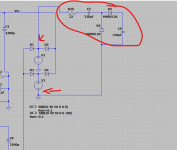
Just look at the main bits of these two circuits. First one shows the parts tagged on to the power supply. You just feed AC from the transformer into the input of the circuit.
Second one is more complex and has a regulated high voltage output together with a tracking regulator on the negative rail. Yu should be able to pick the appropriate parts out that do the multiplying.
Attachments

OP has specifically ruled out your solution, NO AC available:Would a simple voltage doubler arrangement work? Two diodes and two caps.
Just look at the main bits of these two circuits. First one shows the parts tagged on to the power supply. You just feed AC from the transformer into the input of the circuit.
Second one is more complex and has a regulated high voltage output together with a tracking regulator on the negative rail. Yu should be able to pick the appropriate parts out that do the multiplying.
The problem is that the main +/- 40 volts rails are generated and smoothed in a seperate unit and I don't want to modify that, so I need to generate it from one of the existing D.C. rails and in the power amp case.
EDIT:Jan´s suggestion is closer, since 18:72V DC input covers available 40V rail, but that particular converter has fixed +15V output.
Maybe there is a similar one offering -60V
I guess OP needs some kind of buck converter with + (or -) 40V input and -60V output *or* floating 20V DC (or slightly higher) to be used in series with -40V *or* a full inverter, with -60V DC output.
EDIT 2:
There´s a few here with up to 72V DC input and isolated (floating) 24V DC output which may be used in series with existing -40V rail:
Cookies Required
Last edited:
OP has specifically ruled out your solution, NO AC available:
I do apologise 😉:
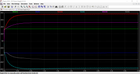
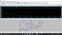
Perhaps something simple like this then. V2 could be a CMOS 4011 (etc) simple low power oscillator. It's supply rail (minus 12 volts) would be a series resistor and zener chosen to minimise power losses. The high voltage output seen here delivering around 15 milliamps has more than enough headroom to use a suitable high voltage 3 terminal voltage reg to give a super clean rail.
Attachments

Hi again folks
Thanks for the suggestions so far - much appreciated.
As JMFahey pointed out, the main problem is no A.C. in the power amp chassis so some form of oscillator and voltage step up is probably necessary either descrete or encapsulated but implemented in such a way as to not dirty the ground or the rails - lots or decoupling needed.
A low voltage DC to DC converter (24 volts or so) is a possibility as long as it is truly floating because it could the be referenced to the existing -40 volt rail.
I think a bit of breadboarding will be in order - and thanks for the sims files.
Also I have just found that the 555 timer is implemented in LTSpice to use as an oscillator 🙂
Kind regards
Mike
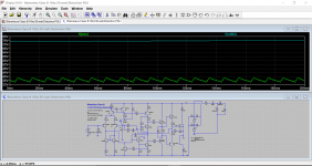
A simplistic oscillator like this one can be adapted for any supply input, 40V or 80V for example, it can have a floating output if you need it, and being sinusoidal, it generates minimal perturbations (probably less than a squarewave operating DC-DC converter module).
It is also inherently short-circuit proof.
It requires a bit of manual work (coil), but this is DIY after all
It is also inherently short-circuit proof.
It requires a bit of manual work (coil), but this is DIY after all
An isolated DC-DC converter is by far the easiest approach, with the proviso the thing might create unwanted noise. Something with an 18V to 72V input range (a standard thing) is the suitable choice for running from 40V.
[ for instance https://uk.farnell.com/xp-power/jte0348s15/dc-dc-converter-15v-0-2a-dip/dp/2475963 ]
[ for instance https://uk.farnell.com/xp-power/jte0348s15/dc-dc-converter-15v-0-2a-dip/dp/2475963 ]
Last edited:
- Home
- Amplifiers
- Power Supplies
- Generating an auxilliary negative rail from DC rails