I would like to get a discussion going over the common types of power transformers and how to extract the maximum performance from them. With the intention that anyone from the novice to the expert will know how to approach a winder with exactly what they need for a given performance level. To avoid snake oil, being overcharged, and to expand knowledge.
Areas I would like this conversation to go:
- Core types advantages & disadvantages, how to extract max performance from each
- Electrostatic screens for core types. Quantity and effectiveness
- Magnetic shields & effectiveness (Example: How effective on EI? Does an R, C, or UI core need one with balanced winding?)
- Winding for the core type? Balanced? Primary one one side and secondary on the other?
- Flux density for core types
- Temp. rise, how to specify
- Insulation MΩ, how to specify
- Ambient C°, how to specify
- Core material, grain oriented, M6 or Hi-B, Amorphous?
- Winders in the USA and abroad (especially if weak vs dollar)
Like a manufacturer claiming a level 4 power transformer with silver wiring and teflon for lower noise. I find it hard to believe that silver wiring will be better than copper for a power transformer.
A power transformer wound on nano-crystalline as the next best thing. Wouldn't this increase high frequency noise?
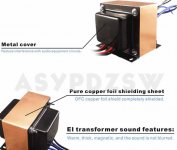
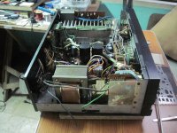
A Chinese manufacturer on eBay claiming that this is well shielded. I thought it was the winding and not the core that needed shielding.
A power transformer wound on nano-crystalline as the next best thing. Wouldn't this increase high frequency noise?
A Chinese manufacturer on eBay claiming that this is well shielded. I thought it was the winding and not the core that needed shielding.
Attachments
Teflon has a dielectric constant of 2-2.3, hence lower capacitance than polyester with around 3.3.
Very seldom is a power transformer required to have a low capacitance between windings.
What is usually required is low capacitive coupling between windings.
This is most effective done by putting earthed static shields between the windings.
Teflon "fumes" as the result from a burned transformer or flash-over are super toxic and present a serious health risk!
Silver instead of copper has advantages only at very high frequencies for unprotected surfaces exposed to the atmosphere.
This is because sulfated or oxidized silver surface resistance is about the same as pure silver,
whereas copper surface resistance would be much higher.
Enamel protected copper wire is practically just as good as silver.
The tiny resistance-difference between copper and silver has been overcome more than 20 years ago by highly refined copper.
The broad industry has not yet made use of that, probable because it is not enough cost effective.
Copper wires are still produced inferior to what would be technically possible.
I am much more concerned about the possible use of copper scrap for the production of new winding wire.
Silver winding wire is a complete waste, the small difference in resistance can easily be compensated by running
the winding some 7 deg cooler.
Amorphous cores offer lower iron core losses.
This is a advantage for distribution transformers in the grid because during holydays or during the night they often run at
very low load where core losses are highest.
In small power transformers they only increase weight size and cost unless the intention is to use them 50+ years most of the time unloaded.
Last edited:
A Chinese manufacturer on eBay claiming that this is well shielded. I thought it was the winding and not the core that needed shielding.
At least the copper "belt" wont do no shielding, it is the wrong way around, it would screen some strays if it where positioned the same way the windings are.
Last edited:
The tiny resistance-difference between copper and silver has been overcome more than 20 years ago by highly refined copper.
It's not about DCR, there are marked differences in the behaviour of silver and copper when operating within a magnetic field. I agree the electrostatic shielding/flux band should run across the open ends of the bobbin, also under the end bells and connect to mains earth. There are also benefits in driving the power transformer with an isolation transformer that uses a centre tapped secondary connected to mains earth and/or signal common.
HK
Last edited:
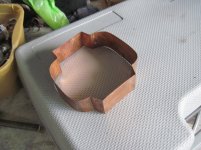
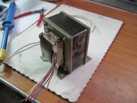
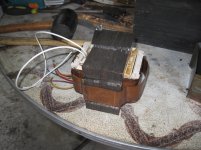
the way the Japanese did it, with belly bands of copper about 0.3 mm thick, and a mu metal wrapping around the perimeter of the core, two or three laps around and then welded...then the enbells are connected...
i converted an Alpine/Luxman LV-105 from the japanese standard of 100 vac to 230 volts...
i converted an Alpine/Luxman LV-105 from the japanese standard of 100 vac to 230 volts...
Attachments
No trust here for the Chinese (having lived there).
The amount of "easy" China(ese) bashing is becoming irritating on forums like these.
Be aware that welfare level in western countries are also possible "because of" how Chinese economy works, despite the criticism you might have.
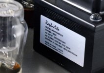
How so does your transformer numbers do not compute?
Because adding the secondary powers does not match 150W?
It does not say a thing...
What does make sense is measuring the EI dimensions and stack, and it's lamination thickness, and check the power that a transformer with this core is able to deliver.
Checking the dimensions it seems to be an EI96.
Even with mediocre iron quality of 0.5 mm lamination thickness, a 50 mm stack could deliver 150 W.
When the transformer is wound with a lower T, and therefore "does" some 100 W secondary power, you even might have a very neat transformer.
Even this isn't really true. If you allow lots of flux, transformer power can be quite high and regulation will look really good. That's not necessarily the best design choice though. Knowing the DCR of the primary winding of such a transformer would be somewhat helpful in taking a less than random guess at its capabilities.What does make sense is measuring the EI dimensions and stack, and it's lamination thickness, and check the power that a transformer with this core is able to deliver.
No trust here for the Chinese (having lived there).
I've had no issues with Chinese power transformers. Output transformers from China I have yet to try (much trickier to design them well), but I expect that's a "get what you pay for" scenario.
In general, it is standard to design a transformer such that the copper losses roughly equal the core losses.
MIT released some good publications in the 1950s about pulse transformers when the military declassified some of the documents on radar systems. Although we aren't dealing with pulse transformers here, most of the principles still apply.
It's not about DCR, there are marked differences in the behaviour of silver and copper when operating within a magnetic field.
HK
And what would that difference be?
The only difference I could think off is the even tinier difference of the DCR related skin depth at high frequencies.
Even this isn't really true. If you allow lots of flux, transformer power can be quite high and regulation will look really good. That's not necessarily the best design choice though. Knowing the DCR of the primary winding of such a transformer would be somewhat helpful in taking a less than random guess at its capabilities.
What is not true about that?

What do you mean with "allow a lot of flux"??
Given the core parameters the properties of the transformer are also known....just physics.
Within the margins flux density can be varied when asked for.
Within the margins flux density can be varied when asked for.
For comparing a "noisy" 100VA transformer running 16 kGauss and a quiet transformer running 7 kGauss, the quiet one will be less than half the VA of the noisy one. That's a very wide margin.
Nonsense, equal copper and iron losses means only the theoretical loading point where maximum efficiency is achieved,In general, it is standard to design a transformer such that the copper losses roughly equal the core losses.
this would be totally uneconomical and this is NOT the standard design goal.
At line frequencies iron losses are only a fraction of the copper losses even with lower grade iron.
A transformer used at a loading where copper losses equal iron losses would be totally under utilized.
Last edited:
transformers can deliver power more than their design suggested, until it overheats and or saturates and blow out smoke.....
running a power traffo below its designed VA makes it run cooler and vice versa....
traffos with rectifications run warmer than traffos with purely resistance loadings....
running a power traffo below its designed VA makes it run cooler and vice versa....
traffos with rectifications run warmer than traffos with purely resistance loadings....
In general, it is standard to design a transformer such that the copper losses roughly equal the core losses.
true if maximum efficiency is desired under load...
i never build my traffos that way, my priorities are lower core heating, all the time...
while i do short circuit testing traffos at times on my big traffo builds, that is just to confirm my calculations... for small traffos of less than 500 va, i never bothered...
- Status
- This old topic is closed. If you want to reopen this topic, contact a moderator using the "Report Post" button.
- Home
- Amplifiers
- Tubes / Valves
- Power transformers - Specs for max performance, core types and where to find them