Good day,
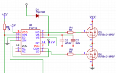
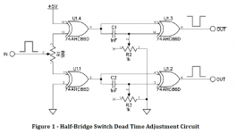
I am building a class d amplifier. The modulate stage is working just fine but the gate driver outputs a 60Hz sine wave. I am using the set up as seen in the image below. the supply voltage on the IRFB4019 is 28V. The input pwm signal are inverted using a xor gate ic and the dead time is set using a 1nF and a 1k pot. I simply don't understand why I am not getting an output. can somone please help.

I am building a class d amplifier. The modulate stage is working just fine but the gate driver outputs a 60Hz sine wave. I am using the set up as seen in the image below. the supply voltage on the IRFB4019 is 28V. The input pwm signal are inverted using a xor gate ic and the dead time is set using a 1nF and a 1k pot. I simply don't understand why I am not getting an output. can somone please help.

You need to show the full circuit, what you have there looks ok.
Is HIN and LIN oposite phases ?
Is the PWM being modulated by your audio signal ?
Is HIN and LIN oposite phases ?
Is the PWM being modulated by your audio signal ?
View attachment 818610
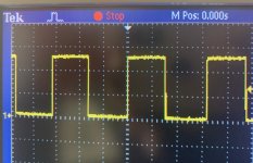
PWM output from the comparator. I tried the IR2110 test on found on youtube. It basically checks if the IC is working, I am getting a square from the high side but the low side is not working.
Is there a LIN signal going into 2110 ?
Yes, i used a inverter to create the inverted signal. Still no square wave output. Then i tried the xor gate to invert the signal, still no luck. Do this mean that the IC is not good?
Yes, i used a inverter to create the inverted signal. Still no square wave output. Then i tried the xor gate to invert the signal, still no luck. Do this mean that the IC is not good?
You need to check signal around XOR gate to make sure they are going low and high ok. I suspect R3 isnt adjusted right.
C7 is completely spurious, C6 can be as little as 22nF for that MOSFET and it'll hold enough charge to drive the gate. The lowly 1N4148 is being stressed every time this circuit is powered up as it may carry a spike of several amps to charge up C7 - the bootstrap capacitance only has to be enough to charge the MOSFET gate without drooping more than 10% in voltage, its often chosen to be 10+ times the effective gate capacitance. It is crucial that its is very low inductance.I am using the set up as seen in the image below.
Since class D using a high switching frequency there is no problem at all with the bootstrap cap discharging due to leakage, which would be a reason to increase C6.
D1 needs to be connected to +12V.
- Home
- Amplifiers
- Class D
- Class D with IR2110 driver


