I’m attempting my first build of an amp. I am doing this to learn. I am using the cmoy design. The power supply tests fine (4.8v and -4.8v) and the light turns on but no sound. I’m not always using optimal parts but was hoping I could make it work. What did I do wrong?
Attachments
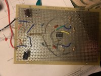
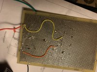
It is hard to see from pictures, however voltage checks should show any problem.
I can see the IC is a 5532 and so you need to begin by measuring the DC voltage on all the pins of the IC. All of them except the supply pins should read approximately zero volts DC. That is the first thing to do.
I can see the IC is a 5532 and so you need to begin by measuring the DC voltage on all the pins of the IC. All of them except the supply pins should read approximately zero volts DC. That is the first thing to do.
It is hard to see from pictures, however voltage checks should show any problem.
I can see the IC is a 5532 and so you need to begin by measuring the DC voltage on all the pins of the IC. All of them except the supply pins should read approximately zero volts DC. That is the first thing to do.
Hi, I did this and for some reason I’m getting 7-8 volts on the positive side and negative 1-2 on the negative going into the op amp. I get sound but only in one channel but it’s distorted. What can I try?
Last edited:
Changing the op amp fixed it but only getting sound in one side
Okay the power supply voltages are now correct but the output voltages are not matching and there is sound only on one side. The output voltages are 0.9mV and 1.8mV
Output voltages of 0.9 and 1.8 millivolts are fine. Anything up to around 100 millivolts offset would be OK for the 5532 depending on actual circuit.
So one channel works OK and one doesn't. As I mentioned, its difficult/impossible to work from pictures but what I would do is look at each pin of the IC in turn and make sure it connects only to the part it is supposed to and that that part also goes where it should. It's very easy to make little mistakes you don;t always just spot.
Make sure you haven't accidentally got the input also shorting to ground.
Don't give up on it")
If you get stuck then post the actual circuit diagram you used and we'll see what we can come up with.
So one channel works OK and one doesn't. As I mentioned, its difficult/impossible to work from pictures but what I would do is look at each pin of the IC in turn and make sure it connects only to the part it is supposed to and that that part also goes where it should. It's very easy to make little mistakes you don;t always just spot.
Make sure you haven't accidentally got the input also shorting to ground.
Don't give up on it
If you get stuck then post the actual circuit diagram you used and we'll see what we can come up with.
Output voltages of 0.9 and 1.8 millivolts are fine. Anything up to around 100 millivolts offset would be OK for the 5532 depending on actual circuit.
So one channel works OK and one doesn't. As I mentioned, its difficult/impossible to work from pictures but what I would do is look at each pin of the IC in turn and make sure it connects only to the part it is supposed to and that that part also goes where it should. It's very easy to make little mistakes you don;t always just spot.
Make sure you haven't accidentally got the input also shorting to ground.
Don't give up on it
If you get stuck then post the actual circuit diagram you used and we'll see what we can come up with.
Now the right channel is playing out of both sides.
Yay it finally works! Wired a jack wrong for one thing.
6A844389-EEC0-46FA-9837-C4C0E1ADB1FD | Alon Wolman | Flickr
6A844389-EEC0-46FA-9837-C4C0E1ADB1FD | Alon Wolman | Flickr
Last edited:
 well done.
- Status
- This old topic is closed. If you want to reopen this topic, contact a moderator using the "Report Post" button.
- Home
- Amplifiers
- Headphone Systems
- Help with first build (cmoy)