Can't figure out subwoofer tuning

Hi all!

I have 2 B&C 18PZB46 and 2 B&C 18PS46 woofers.
They're all in identical 185L sub boxes. (185L without the woofer, is that the correct figure to use?)
Right now all these boxes are tuned to about 50Hz,
However they don't sound as great and get as loud as I'd hope

Is there anything I can do to the tuning frequency to help with some of my problems? Any other solutions are appreciated as well of course!
I'd rather sacrifice some sound quality and have them be a bit louder, than the other way around. Some distortion isn't THAT big of a deal.

I've also added the WinISD calculations I've done, but I'm not completely sure if they are correct, since I'm not too experienced

Thanks in advance!
-Daan

Datasheets
18PZB46: https://www.bcspeakers.com/media/W1siZiIsIjIwMTMvMDMvMTEvMTUvNTIvMzAvNTQyL2ZpbGUiXV0
18PS46: https://www.bcspeakers.com/media/W1siZiIsIjIwMTMvMDMvMTEvMTUvNTIvMjYvMTE2L2ZpbGUiXV0

Attachments

Mark Audio CHR-70 V2 in wooden boxes (UK)

Now sold.

Full range drivers in wooden bass reflex boxes. Some damage to the top of one box (picture). Drivers undamaged and working fine. £40 will post for an additional £10 or collect from Warrington WA4.

Sold

Attachments

  • IMG_20230529_150850151.jpg
    IMG_20230529_150850151.jpg
    533.3 KB · Views: 93
  • IMG_20230529_150859289.jpg
    IMG_20230529_150859289.jpg
    390.2 KB · Views: 98
  • IMG_20230529_150907262.jpg
    IMG_20230529_150907262.jpg
    604.3 KB · Views: 92
  • IMG_20230529_150915908.jpg
    IMG_20230529_150915908.jpg
    612.1 KB · Views: 96
  • IMG_20230529_150920574.jpg
    IMG_20230529_150920574.jpg
    187.5 KB · Views: 96

Woofer for a 3 ways...

Hello,

I have a two-way bass reflex with 6"+1" Peerless drivers and I'm wondering to add a woofer or a sub and cross it about on 200/300hz. Also, I'm looking for some new project, starting with a 2 ways KIT. I can measure and use ARTA (if I remember how to do...) but I'm not so skilled in electronic so I prefer to start with a two-way KIT and add a woofer on my own.

So, the woofer I'm looking for, will first play with my Peerles mid/tw and then maybe... with new Satori or Scan mid-woofer.
What I am looking for is a good 10" woofer for sealed enclosure of max 40/50 litres (1,7cu ft), it would be active with 250W amp and DSP, it has to go up, say, to 500hz. I don't need deeeeep bass and high SPL, just 40hz with good transients and the ability to blend well with a 5" or 6" mid. As I use an active amp ... sensibility is not the main problem, I think.
I'm trying to simulate some Wavecor, WF275BD01 seems to be good but F3 is about 50Hz, if I find something that goes deeper is better. There is also Wavecor SW223BD02s (and SW270WA01)but I don't know if they reproduce well mid-bass frequencies, an what about CSS SDX10 ?

Any advices?

Thanks!

For Sale huge tubes and related parts estate sale JUN 17-18 Irving TX

The gentleman was a prolific experimenter and builder. This is his 'stash' and occupied over 500 sq ft in the home. There is also two sheds to explore. It'll be worth it to go. There are hundreds of transmitting, receving, and power tubes, plus all the other parts needed to build a wide variety of tube gear, and also some solid state items. Please see flyer, which is also online at https://www.bunkerofdoom.com/brady_estate.pdf

This is not mine. Please do not ask me about specific items etc. I am merely helping our DIY group by posting this for the benefit of local members. Note one thing please; their flyer says it all has to go and will be priced to please.

I do not consider this a commercial post at all. Their concern is that all these tubes and parts etc. will be pitched out in this age of smartphones and instant gratification.

Attachments

Amplifier modules for 3-4 way active speakers

Finally, I'm starting a project to build three-way active loudspeakers. It will be a modular construction, bass section and midrange tweeter. Initially i wanted to use an amplifier with DSP like Hypex FA503 but now i'm leaning towards MiniDSP Flex Eight + external amplifiers. MiniDSP Flex Eight has several advantages - among others, it allows the construction of a four-way set and has the option of Dirac Live room correction.
So I need amplifiers.
Which Amplifier modules do You recomend for bass (I want to use 21" woofer - construction similar to Toids DIY Audio - Earthquake 21). Closed cabinet with some DSP correction requires some power. For home use I think 500W/8Ohm should be fine? I don't know which amplifier module to chose - one of the sure products?
Which amplifiers to choose for the mid-range and tweeter section? I'd like something like Puri modules but it's not in that price range (maybe one day). Speakers drivers will be high efficiency so I need very quiet and clean amp (especially for CD tweeter). For mid-range it should be some more power and still very quiet and clean amp modules.
I need good but cheap amps modules for a start 🙂 I would like to fit in three ways but a large woofer can force four ways

Pentode push-pull screen question - voltage in relation to plate

I'm currently going through running ltspice simulating Rob Robinette's EF80-based push pull output JCM800 Marshall amp, and I have a simple question. Usually you'd have the pentode screen grid at a lower voltage than the plate but the sim indicates that the design (with a 1K screen resistor) is higher than the plate. So even if the ltspice model is wrong, the resistances and currents means that the voltage drop for the screen is smaller than the voltage drop over the transformer at idle.

However if a PP output transformer is 22.5:8, the resulting grid is 1/4 of that from my understanding so around 5K6 in terms of plate resistance, the screen resistor plus the choke is 1270R (1K+270 DCR). The diagram below gives the schematic but ignore the voltages noted on the diagram, I've given the measurements below:

Screenshot 2023-05-26 at 09.32.49.png


Note the diagram and the components follow Rob's design, although I have a separate pre power supply and so there's less current through the choke (but even an extra 5mA at 270R is only going to drop 1.35V).

B+4 = 324Vdc
B+5 = 327Vdc
Up = 288Vdc, Ik = 8.6mA
Ug2 = 322Vdc, Ig2 = 1.7mA

So you can see that the grid is sat above the plate which is not healthy from all my self-taught knowledge. Is there some difference between pentode screen use on HiFi vs Guitar amps that I'm not aware of?

If I add 20K to the screen resistors, it reduces the screen voltage below the plate and the screen current remains about the same (within spec). The plate swing drops and from my knowledge that would also make the kink more pronounced as it's not particularly negative below the plate). However I've never heard of 20K+ screen resistors (this is my first pentode output push pull).

Any wisened thoughts would be welcome.

B&W 700 Series Tweeter Repair

Hi Folks,

I would like to tap your brains for repair on a Bowers Wilkins 700 Series Tweeter. I have attached a thumbnail schematic. Its the classic and almost hilarious story of kids pushing in the dome and wrecking voice coil. B&W spare parts in Australia list the replacement part ZZ14137
as unavailable. I have tried replacing it with the ebay diaphragm but results very unsatisfactory.

Ay suggestions on how I might proceed? Anyone reputable who make replacement parts for B&W or any way I might replace the whole assembly? If so how to match a replacement tweeter to the B&W crossover?

Many thanks

Luke

Attachments

  • 703 tweeter.JPG
    703 tweeter.JPG
    88.3 KB · Views: 851

QUAD ESL-63

I am very close to buying a pair of Quad ESL-63's that have been upgraded by Kent McCollum of Electrostatic Solutions. Hopefully I will take delivery next Friday. I wanted to ask any owners of the ESL-63's what amplification you are using and brings out the best with these speakers? I may be willing to try SS, my preference has been using VTL 100 to 200 wpc monoblocks for the last several years on my various Acoustats. I am a big fan of the EL34 tube. I listen at comfortable levels, very seldom over 90db. The speakers will be in a room that measures 13 ft. long x 12 ft. wide x 8 ft. ceilings. I listen to everything except opera and country twang. Any opinions would be much appreciated.

Small Wide-Range instead of Small Midrange+Tweeter in Multi-Ways?

My next speaker project is embryonic at this stage but I'm starting to think about what I'd like to try. It will certainly be a pair of active multi-way floor standers for hifi stereo music; as a rough indication, around 85dB with 15dB peaks at a couple of meters would likely suffice. As part of it, I would particularly like to include a small upper-midrange driver (say about 3") from roughly 800hz upwards.

Some years back I'd unquestionably have crossed that to a tweeter. However.. I'm now old enough to not hear beyond about 12khz (and likely that will drop more over time). I don't need to listen off-axis beyond what would cover one listening chair (or a two-seater, at most) at a few meters. So I'm strongly tempted to use one of the small wide-range (or full-range) drivers for everything above 800hz or so. It would be a compromise, but not sure how much of one. The alternative, crossing to a HF tweeter isn't completely free of compromise either, and in this case it would involve an extra active way.

Some of these little wide-ranges do seem quite potential for that use. By way of example some measurements that Zaph made in Aug 2010 on one of the flavours of scanspeak 10F (the 4424G00) though of course there are alternatives (I just showed this one due to finding decent measurements of it).
0-15-30-45-60 degree FR:
Scan-Speak-10F-4424G00-FR-offaxis-0-15-30-45-60.gif
Scan-Speak-10F-4424G00-HD.gif
Scan-Speak-10F-4424G00-CSD.gif
On paper, possibly quite a reasonable choice for my needs. Just wondered what other people think of the idea?

Thanks,
Kev


[BTW I do realise one can use a Full-Range crossed lower, or even not at all. But the use-case of interest to me here in this thread is only as the top end in a multi-way (with 10" and probably ~6.5" drivers for the lower frequencies), hence posting in the multi-way forum].

Transmission Line with 4 Drivers

Hi Folks,

I am about to start designing a transmission line bass guitar enclosure with four 10 inch woofers. The drivers will be run full range and smooth midrange is not a necessity but minimising peaks and troughs in the 100hz-250hz range is important.

In the past I have designed and built 2 driver transmission line subwoofers and bass cabinets using AJ Horn to model the driver locations. This is generally one driver at ~1/5 line length with the other at ~1/3 line length

Can anyone provide advice on placement of 4 drivers in a transmission line arrangement?

For reasons surrounding avoiding comb filtering, I would like to avoid placing two drivers side by side at the ~1/5 position and another two side by side at 1/3.

Any advice on how to model 4 Drivers, all at different positions in the line?

Ideally all 4 drivers will be 10 inches apart along the line. Can anyone offer advice on how this will work with nulls and peaks above the fundamental tuning and were the drivers would be ideally placed?

Thanks in advance.

ADAU1701 Raspberry I2S Driver

Hi,

in my current project I'm using an ADAU1701 DSP board from Sure Electronics (~20$) in combination with the digital I²S audio output of a Raspberry Pi 2b.
I searched if there is any existing driver which fits the special requirements, but didn't find something.
Therefore I modified some existing device tree overlays and changed them to match the special conditions of the ADAU1701.

The ADAU must run as clock slave at it's I²S inputs, which wouldn't be an issue, if the Raspberry could produce the MCLK for the ADAU as well. In fact that's not possible, the Raspberry runs as clock slave. The ADAU is configured as clock master and its output bitclock and LR-clock is feed back to the input of the serial interface. As well, the clock outputs of the dsp source the clock pins of the raspberry.

I wrote a brief installation guide on my homepage: Installation Guide ADAU1701 Driver.
The files are available on Github: ADAU1701 I2S Driver Github Repo.

The installation is quite simple. No compiling is necessary.

The driver works good in combination with Raspbian. The resampling of audio material which isn't sampled at 48 kHz can be done with a short ALSA config file (due to oscillator used on the dsp - 12.288 MHz). The resampling is absolutely necessary, because the whole dsp program is compiled with a fixed sample rate and moreover the adau1701 doesn't have an ASRC. That's why a change of the sample rate during operation is not possible (like DACs configured as clock slaves or with GPIO pin to change the necessary oscillator would be able to e.g. the whole HifiBerry devices)!

I also documented the integration in the current Volumio version (2.389). The installation is nearly as easy as in Raspbian.
What makes Volumio interesting, is the opportunity to use AirPlay to stream audio content to the Pi. In combination with the possible mobile hotspot of Volumio, Airplay could be a much better mobile streaming solution as bluetooth is right now.

That's where the problem begins. The current version of Airplay (vers. 1) transmits the audio at 44,1 kHz/16 bit.
In consequence, audio must be resampled to use it with the dsp. But the Shairport-sync module is sending the audio data directly to the hardware to ensure the time stamp which is necessary for multi-room applications (as I understood so far).

I'm currently working on that issue, but my knowledge of audio linking on lower software levels is not that good. It would be nice if someone with more expertise could help.
Also people who test and give feedback would be great. :smash:

PS: I attached two pictures.
- The testing setup: Raspi 2b, Sure ADAU1701 DSP and programmer board (USBi like)
- A working screenshot of the Sigma Studio test project

Best regards,
Markus.

Attachments

  • IMG_3137.jpg
    IMG_3137.jpg
    647.8 KB · Views: 1,633
  • testsetup.PNG
    testsetup.PNG
    57 KB · Views: 1,621

NAD 3155 troubleshoutting

Hello. Newbie here. I just got a NAD 3155 with some problems.
The amp is entering in protecting mode and i dont know why, also only one of the inputs works.
I got all the capacitors new but for the moment i only replaced half. I tested for the dc voltage into the test points like the service manual say and i get a variable voltage in the left channel quite high. If i make the both potentiometers of the left channel to the minimum, i get a lecture of around 0.50/o.55mv and is getting in and out of protection mode.
After i replace the rest of the caps, what should i look for?

NAD 1020 series 20 Rebuild: Hi-pass filter in audio path on early units?

Hi, I'm rebuilding a NAD 1020 series 20 preamp.
When I look at the web available service manuals, I don't see this filter. All the rest in the audio path is the same as in the schematics I can find.
This HP filter consists of C307 1uF and R321 27k and sits in the audiopath between the output of the amp section and the phones PCB R301. See image below.

I haven't finished the rebuild yet, but I'm already very interested about your thoughts on dropping, modifying or keeping this filter.

Scherm­afbeelding 2023-05-29 om 15.03.46.png


Thank you!
Chris

Marriner dual PCM56 NOS DAC

Orders now are open on 'Marriner' DAC boards, ready built and tested. PM me and please don't forget to include your chosen payment method and location so I can quote you inclusive of fees and shipping.

Marriner uses the same I/V stage and filter as 'Dark LED' but is a single-board solution so it also contains the DACs. The DAC section is based on a pair of PCM56 per channel and the DAC's power rails are fed from low noise IR LEDs via discrete transistor regs. Two DACs per channel are used to get lower noise than a single one but also to even out the production variations in output current which are inherent with these chips. The PCM56 chips are pre-selected to give a close inter-channel match in output level.

Marriner needs a 4 rail PSU (+/- 18V for analog, +/-8V for feeding DACs). Its peak output level is selectable by resistor link to 1 or 2VRMS. The input format is I2S, three wire (no MCLK required). Current consumption on all 4 rails is below 100mA.

Preferred payment method is via Wise which typically adds a 2% fee. Our receiving currency is CNY, alternatively USD or Euro. PayPal may also be used, in USD but will attract a slightly higher fee, 4%.


Price for a Marriner built and tested unit including top-mounted 9th order filter board : 1120RMB (~USD157)


Physical dimensions: 100mm * 65mm, max height 25mm. Fixing centres : 90mm * 60mm, M3 holes.

Shipping is in addition and depends on your location and speed of service. Courier (FedEx, TNT, DHL) typically takes 8 - 10 days and e-packet four to eight weeks. Not all locations can be serviced by e-packet though.

_20230329175702.png


_20230329180439.png

Power supply module for TPA3250 or similar

Hello,

this is my first post. I’ve discovered this forum years ago and gained lots of helpful information here. Thank you!

Maybe someone can advise me on this matter:

For education purposes I need mono or stereo amplifier modules that I can customize a bit for my needs.
I've decided to try this with the TPA3250. I've found some inexpensive assembled boards on the internet.
Now I'm looking for a suitable DC power supply, in the range of 18 - 30V and ~ 4A.

I'd prefer using a linear power supply instead of a switching PSU. But I'm also open to recommendations for quality switching PSU.

For me it's more important to keep it not too expensive because it is needed in a medium quantity (8 - 16 pcs.) for experiments with unconventional speaker setups, exciters/shakers, in the context of sound art installations.

Is there anything pre-built based on - for example - the LM338 or something similar? Or can anyone recommend and point out a schematic/layout from an open hardware manufacturer. There is probably already something written here that might help me with me questions.

Thank you very much.

More bass from 35Hz rated MB Quart 600 than 25Hz rated Impulse 74?

To the speaker Wizards,

First of all im not sure if this is the right forum. Let me know. Second the speakers in question might not be familiar. Still im curious about your thoughts.

Recently aquired Impulse 74 transmission-line speakers which are rated at 8 ohm, 91dB, 25Hz to 25kHz.
Expecting them to deliver tons of bass for my electronic music.

They replace the MB Quart 600
Rated at 4 ohm, 90dB, 35Hz to 31kHz.

Surprisingly the Impulse delivers much less bass to my listening spot! It sounds much more clear and open, far surpassing the Quart's soundstage. Though the lack of bass leaves me somewhat unsatisfied.

Could this be due to woofer positioning and room acoustics?

The impulse is much taller and has the woofer about 50cm higher above the ground. Both are front ported two-way designs build in 1992. The impulse now stand in the same spot where the Quarts used to be.

Im hoping there is a possible explanation that could lead me to a fix or help me descide wether to keep or resell the impulse 74.

Much thanks and cheers,

Ruben

20230430_201637_HDR.jpg

(The impulse making the quart look small)

Sansui G-22000 zero bias in one channel

Hello all, I have been working on this amp for some time and am running into an issue where one channel will not bias. The Output transistors have the 80V +/- collector voltages, the Emitter voltage correctly sets very close to 0mV and the Base voltage is adjustable just like the good channel at .3 to over 1.3V.

I have tested all of the resistors in the output circuit as well as many other components on this channel. The only outliers in terms of voltage differences I have found is that there is no voltage drop across the emitters nor across resistors R39 and R40 which lead to the +/- base voltage supplies.

I could go into more detail regarding the work that has already been done but I wanted to make my question as concise as possible.

Screenshot 2023-05-24 092509.png


Screenshot 2023-05-24 092552.png

NAD310 Repair

Hi Everyone,

I have picked up a faulty NAD310, ive traced the fault to the output stage, a failed BUK555-60B. This device seems to be obsolete and other than used or possibly new counterfeit devices, im looking for a modern alternative device.

Has anyone had to repair/replace one of these before? if so, what did you use?

I am considering trying an IRL540N, but other than a similar power rating and similar Vgs theyre not a perfect match and i dont want to turn this amp into a big Oscillator, or damage anything else in the process of trying to repair it.

Thanks in advance, any thoughts welcomed 🙂

Taylor

Help - I screwed up the Ampcamp 1.8

Hello this is my first time here and I need some advice. I finished up the v1.8 on the weekend and before I fired it up I went through the resistance and voltage diagnostics as per the v1.6 build guide. A couple of problems:

  • On channel A the S leg of Q1 reads 13.6 V - should be 0 V
  • On channel B the resistance on R5 is OL, should be 10.9 kohms
The weird thing is the amp works - both channels make sound and no smoke so far. LEDs work and seem identical. I think I am hearing some distortion but I may be imagining that? In any case the numbers are wrong and need to be fixed.

Any help will be greatly appreciated.

Having trouble completely removing solder from through-hole joints

I can get the surface-level solder to come off, but components always end up stuck in place by solder in the hole that I can't get out. For two-legged components I'll heat one leg and pull from above until it releases, but this doesn't work as well for multi-legged parts. I feel like I'm doing something wrong, like there must be a cleaner, simpler method that pulls all the solder out of the hole.

I've used flux, I've tried priming the wick with a dab of solder, nothing makes any real difference.

Definitive LM1875 thread. Discuss and Build

Here are my suggestions for setting up the LM1875.

First schematic shows how I like it.
Gives like 27 Watt into 8 Ohm. 32 Watt into 4 Ohm.
The potentiometer is to adjust DC offset on the output.

Second image is the Fourier Analysis.

Third image is the AC Analysis. Upper frequency is like 400kHz.

For 4 Ohm speakers I recommend transformer 2x15VAC.

Attachments

  • LM1875 Schematic 01.jpg
    LM1875 Schematic 01.jpg
    243.8 KB · Views: 665
  • LM1875 Fourier Analysis 02.jpg
    LM1875 Fourier Analysis 02.jpg
    154 KB · Views: 608
  • LM1875 AC Analysis 03.jpg
    LM1875 AC Analysis 03.jpg
    229.5 KB · Views: 612

My_Ref Requiem - a new iteration

Hello everyone,
Being a long time fan of Mauro's design and it's sound, i wanted to take the My_Ref to the next level.
This has similarly been done previously, resulting in the excellent sounding FE (fremen edition) for example. A lot of good progress has been done to arrive to Rev C, Evo, and FE so this is definitely an effort build on the shoulders of giants, so to speak. FE is considered the current go-to for My_ref editions so i might use it for comparison in the following text, but it should in no way be taken as lessening the effort that was put into it or it's results.
However, I wanted to adress a lot of the limitations i found with these designs and the result is a new re-imagining of the My_Ref, in honor of Mr. Penasa. I will try to layout some things that have changed:

Improved PSU
As a comparison, FE main powersupply performs its function well, but is fairly simplistic and relies on massive capacitors for filtration, increasing both PCB size requirement, being harder to fit into a case, while offering lower PSRR.
My_ref design is very low in distortion and noise floor so we must pay special attention to PSU.
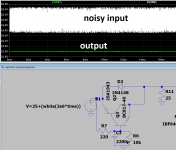
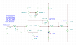
We can improve the situation, AND at the same time be more efficient on the use of capacitors by using capacitance multiplier.
It works by multiplying the capacitor on the base by the gain of the sziklai pair, its gain is calculated as hfe1 * hfe2 + hfe1
The beta (hfe) varies with current, so we will only guesstimate in the ballpark here but for 2SA1943 and bc817, its about 60*300 = 18000, multiply that by the capacitor value and its your effective value....it's a lot of filtering.
1651248881281.png

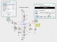
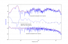
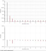
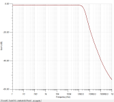
The results are even better for a normal PSU, notice on the simulation the noise has a magnitude of almost 1V but it is effectively filtered out.
What this means effectively is that you are not bound to only expensive PSU solutions, you can easily use common SMPS for power, further lowering cost and size requirements, while giving better performance than its predecessor.
There are also two thick holes for leads where you can connect them to a cap bank somewhere else inside the case, but dont get too overboard with this, there is no need really.
Another benefit is more removal of high order harmonic content from the noise spectrum. Another benefit is the higher the load, the more filtering you get.
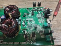
On the PCB these are mounted very close the LM3886, both for performance, layout, but also potentially cooling reasons as you can then heatsink mount them. This is recommended but perhaps not even necessary if you listen to about 10-20W volumes, as they only dissipate in the hundreds mW range then.[/SPOILER]


Improved Opamp PSU
We have a MOSFET based regulator with high PSRR, while at the same time being able to deliver a lot of current.
1651251757950.png

Just as a comparison, here FE uses also a CCS, a simple LM317 and one resistor. It works good enough though.
Special thanks to Tibi on this one!


Solid state relay
The original circuit for the relay is simple in design and performs very well, but an SSR offers advantages over a mechanical one. My_ref is not so powerful to warrant a lot of concern over it but i wanted to offer the option to use an SSR, so now you can either choose to just use the G5LE relay or go for an SSR. Depending on your wishes and budget, you have the option to choose for yourself 🙂[/SPOILER]


New BOM
There has been a lot of talk of the effects of various components on the sound of the amp, in particular output resistors. You have an option for a normal axial resistor, TO-220 packages, but most importantly, and my recommendation, the use of ISA-PLAN manganin/zeranin power SMD resistors from Isabellenhuette. They sound excellent, have under 3 nanohenry of inductance and are IMO a superior option.
A lot of the stuff said that applies for FE applies here as well, for bypassing C9 capacitor (jumper provided) and which resistors are important to get right (12K and 390 are critical). The stock compensation here is for an OPA1641, but legacy backwards compatibility is retained with LM318 with its compensation (jumper provided). 150pf capacitors are very good PPS (polyphenylene sulfide film capacitor) from panasonic, and so on..
When using the OPA1641, C9 is bypassed, and i would especially recommend this setup for nearfield or critical listening.
There is an option to use balanced input, albeit as of right now i have not tested it as i dont have anything outputting balanced, so this is definitely a subject of further evaluation. But basically long story short, this board is highly configurable and achieves a lot.
Installation of components is via and interactive html page, highligts position of component on board and you can mark it as complete, makes installation a breeze.[/SPOILER]


Last but also importantly
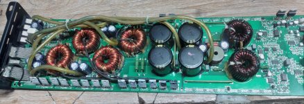
Improved PCB layout

One of the things i didnt like about FE was its unecessarily long traces, and a fairly long current return path for the output (it almost couldnt be longer, it goes diagonally across the entire board). The resistors have marked directionality, despite the components themselves not being directional, and this was never explained (?). Even has a jumper wire for a trace, suggesting this is a 2 layer design (but i dont know this for sure) and he didnt want to disturb the current return of the top trace through the ground (which is good thinking, but shows the kind of compromises made.) All of this made me decide it might be best to start from scratch with an own board.
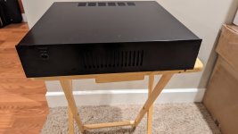
We have a 4 layer board, and the inner 2 are perfectly uninterrupted, except where i want them interrupted with a keep-out zone. There is a lot of copper on this board, copper fills were also used for some critical connections (such as the output, or power rails). It is a compact design, measuring about half the size, at 100x55mm. Actually, i will probably increase the width to 65mm, main reason i designed it this tight to the point everything on the silkscreen is overlapping (unimportant, its just numbers, also with html bom tool you dont even look for markings on board as its highlighted) was for use in a super-compact case.
If anyone else wants the board, i might make a new more "relaxed" one.
IMO, i've made prettier boards, but im pretty happy with how it turned out electrically.
1651252991877.png


The board is designed for ±24.0V to ±32.0V DC input, providing anywhere from 30 to 50 watts. More than enough in my opinion, but it's up to you if its a concern. Side note, but for me this "you must have 500w class-D" talk is just marketing numbers game, proof enough is to see Pass designs of 10-25W sound beautifully and powerfully.
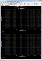
As for distortion measurements, i dont have gear that measures so low currently. Go see how well FE measures, and fill in the blanks in your imagination. But THD-N, while being a good feature, isnt even the main thing of this amp, just icing on the cake 🙂
It can be built both boards for maybe...150$-ish? But the main thing is, you CAN build it with cheaper SMPS, in a smaller case and get top notch performance, so the total system build is actually really good. It was one of the design requirements i wanted to fulfill.

Hmm, what else to say, if i forgot something feel free to ask...a loot more could be said, but i got tired of writing after a while, and a lot of it is carry-over information from previous my_ref's.
Im courious to see any comments or thoughts we are all here in the DIY community to communicate after all.

Attachments

  • 1651249376611.png
    1651249376611.png
    51.3 KB · Views: 235

DAPHILE volume control

Hello community,

Do any of you know the 'technology' used by Daphile for volume control?

I hear a substantial loss of quality when I go from 'Off bit perfect' mode to 'On at 100%' (loss of dynamics, the sound is grayer, more subdued).

Do you know:
— if Daphile uses dithering like Linn so as not to lose resolution by quantization?
— under which bit resolution does Daphile control the volume?
— if a pure digital TC electronic BMC-2 type controller (In and Out in SPDIF) could do better than Daphile?

Thank you all!

LTP Tube recommendations

I am working on a fairly simple balanced line stage that will consist of a LTP driving a balanced source follower output stage. The LTP will use a discrete SS CCS in its tail and will be driven from a balanced source. My B+ is from a Maida regulator with about 250V output, and a regulated 6.3V DC heater supply. I could voltage double if the heater current is low enough. I also have a -20VDC low current regulated supply which I am planning to use for the CCS connection.

I am looking for a dual triode recommendation that is not too finicky (I'm a relative novice when it comes to tube circuit design) that will produce clean output with modest gain (2-3x optimal) and no global feedback. I was thinking of a 6SN7 or 12AU7.

I was also thinking I'd use some cathode degeneration to improve linearity, reduce the gain, and potentially to adjust balance (with a trim pot).

Thanks.

Luxkit (Luxman) A3700II assembly manual?

Hello everyone,
I am looking for a copy of the assembly manual for a Luxkit A3700II amplifier.
I am not sure if this amplifier was every sold outside Japan?
The amp I have seems heavily modified, so with the manual I hope to be able to restore it.
If anyone can help me with a copy of this manual or even the proper circuit diagram for this amplifier will be helpful as well.
Thanks,
Steve.

Need Help With KiCad

Hello All,
I looked over the first few pages of a diyAudio search for “KiCad”, and did not find anything that helps with my problems.

I am using V7 for this project. I have a very simple PCB design, nothing more than a terminal strip and pads to accept the relay pins. The reed relay is quite old (1980’s P&B T10 series, long out of production), but high quality, so I wanted to use them in this preamp project. I was unable to find a datasheet that provided pinout dimensions, so I had to design my own KiCad Footprint. Attachment 1 shows the board (the grid is 0.1270 mm). Running DRC results in many errors. Attachment 2 and 3 shows the two types of errors. I have spent almost a week trying to understand what is going on, but with no luck. What is strange, is that a week before I began this design, I did a separate board for mounting the switches that control these relays, that went without a hitch. So, I assuming it all revolves around my Footprint design, but that is just a guess.

Any help would be greatly appreciated.

Cheers,
ceulrich

Attachments

  • 1 - Board.png
    1 - Board.png
    82.4 KB · Views: 375
  • 2 - Error Message.png
    2 - Error Message.png
    14.5 KB · Views: 288
  • 3 - Error Message.png
    3 - Error Message.png
    17 KB · Views: 308

Purifi PTT6.5X08-NAA-08 + Mundorf AMT U110W1.1

I would like to share with you the my good experience with these drivers able to give extreme performances better than Ceramic drivers.

The distortion is considerably less than that present on my ceramic drivers and I'm not talking about something just measurable but a substantial improvement in listening.

The Purifi mid-woofer integrates perfectly with the AMT tweeter returning a fast and detailed mid-range with plenty of separation between the instruments.

I will share the complete project with a H-frame dipole subwoofer created with a normal pro 18" and active filter.


1684416682405.png

1684416698522.png

(Toronto, Canada): 2 x Plitron 077014201 Toroids 2x18VDC 115/230VAC input - MINT

Just checking to see how much interest there would be for these.

(Qty: 2) Plitron 077014201 toroidal transformers.

  • Dual inputs (115/230 VAC)
  • Output: 300VA @ 8.33A each
  • 2 x 18VAC windings
  • One-shot fuse
  • Potted center
  • Weight: 6.4 lbs each

These were recommended transformers for:
  • Pass First Watt F4 clone
  • Pass F5 Clone
  • The Pass Zen clone.


These were tested for about half an hour when I first got them and haven't been used since.


They do NOT include mounting hardware.


P4260474.jpg
P4260475.jpg

Hello from the Netherlands

Hello to all of you! My name is Cor and I am interested in HIFI equipment from the seventies (especially Philips) and I am repairing this equipment, as a hobby.
In our living room, we have a set up of Philips from the beginning of the seventies, a fish-eye amplifier and tuner and the record player with tip-keys. The CD player is, of course, from a later date; a CD303. The boxes are Motional Feedback boxes, of the type 22AH587.
I am also interested in making some audio streamers with the Raspberry PI. This is also why I came on this forum.

I hope to read some interesting things here, and maybe do some contributions, though my writing in English is rather poor...

Cheers,
Cor

Python Open Room Correction (PORC)

I've created the Python Open Room Correction (PORC) project to generate room correction filters for OpenDRC, or any other convolution engine for that matter. The filter is based on the work of work of Dr. Balazs Bank.

PORC is intended to be a free command line tool. If you desire a fancy GUI feel free to fork this project (or pay for an expensive commercial software package).

PORC allows one to specify a target curve and generate the corresponding loudspeaker-room correction filters. The filters may easily be imported into OpenDRC. I've been listening on my system for the last few weeks and the result is excellent. It even sounds fantastic well outside the targeted sweet zone. Attached is a screen shot of my left channel speaker results.

Room EQ Wizard (REQ) is an excellent (and free) tool for measuring the loudspeaker-room impulse response of your system.

I realize I can do a much better job with documentation; this project is intended to be a work in progress. See the link above for the code.

/Mason

Attachments

  • eqplot.png
    eqplot.png
    171.8 KB · Views: 2,387

S/PDIF performance issues with PCM9211 transceiver

Hi

TLDR: Has anyone experience in PCM9211 in high performance application (<112dB THD+N) - can it do it?

I'm designing a new SPDIF to PCM board using a PCM9211 to replace my AK4115-based solution due to discontinued IC. However, I'm having issues with the performance of the PCM9211.

I've got an AK4493S based DAC PCB that can do <-116dB THD+N with I2S or with my old AK4115-based receiver. However, with PCM9211 I get 'only' -112dB (1kHz). Moreover, the result deteriorates quite significantly with higher frequency. Also, it is sensitive to SPDIF voltage level; going up or down from nominal 500mVpp increases performance, and also the digital signal level heavily impacts the THD+N - mostly via increased noise floor. Also, performance slightly increases with sample rate. The performance is slightly better with Optical input than coaxial. All this is something I haven't seen with any other SPDIF receivers I've worked with.

I've been modifying my circuit and doing dirty layout tricks but nothing has helped so far. I haven't tried to analyse or compare the clock quality coming out of the PCM9211 yet. This is a fairly complex chip but I don't see anything obviously wrong in configuration, also when comparing to EVM config scripts. For example, I use 24.576M MCLK in all cases PLL wide/narrow mode doesn't change anything. It almost feels like this is somehow related to the analog parts of the IC, mainly the PLL. But afaik there is nothing to do about it, it uses an external filter but component values are given in the DS. All caps are C0G and very close to the IC.

Before digging deeper, I'd like to ask if anyone has experience with this IC in high performance applications? Just thinking am I trying to fix unfixable or is there something wrong with my circuit. Any experience is welcome. TBH I'd be a bit surprised if the performance of the IC so 'bad' - but then again this is aimed at AVRs and cheaper end receivers where this wouldn't be a limitation.

Thanks!

Mach One replacement driver

I've been crunching numbers for a proposed new three-way...my low-end woofer I want to use the RS Mach-one fifteen inch reissue. GRS speakers which created a copy of the original, the specs just don't seem to make sense.
I simmed up the driver & as expected the EBP points firmly to the sealed camp, which is as the originals. My point is, the simulations indeed is sealed, but at 578.4 Liters worth...now I sold those speakers at Radio Shack long ago as a kid, and the enclosures are maybe one/quarter of 578 liters worth. Adjusted the SIM for a guess at the originals far smaller enclosure has QTC pushing towards one-point zero, ( 1.0 )...rather flabby uncontrolled bass. What's going on here?, ...did Radio Shack actually make such an uncontrolled particular speaker? Or, are the new replacements that far off from the originals?

-----------------------------------------------------------------------------------------------------------------------------------------------Rick...

Input or Output Pre-amp Volume Control

A viewer sent me the parts to build this "color" pre-amp for my YouTube channel. In the past I did build one of the "universal" single tube pre-amps shown on this website, that uses a volume pot on the output, and it seems to work fine. The idea of this two tube version is to have the ability to drive a lower impedance SS amp with it.

This cathode follower one I am now looking at building is found here.

https://www.cascadetubes.com/the-12au7-cathode-follower-color-preamp/

I redrew his schematic to be easier to read, it looks like this.

color Pre-amp 1080.png


My question is: what advantage or disadvantage would there be to moving the volume control to the front of the pre-amp like this. Is 100K a good pot to use for this or would a 250K work better?

color Pre-amp-front-pot 1080.png


I understand there are many other pre-amp designs that are more "HiFi" etc, so that's not the question, the viewer specifically ask me to build him one based on this design. I'm just curious about possibly moving the volume control to the front end of this design, and which position would work better (and why).

I'm also wondering if the 1.0uf cap paired with the 10K output resistance is why he is seeing the low frequency roll off starting at 50hz he talks about in the website article, and would something like a 4.7-6.8uf output coupling cap avoid that roll off.

Thanks in advance!

Marshall Valvestate 8080 buzzing

Hello! I've just got a Valvestate 8080 for a decent price (a good deal, but not cheap) and unfortunately found out a bit too late that when turned on, with nothing plugged in and all knobs to 0, it has a constant, relatively loud buzzing sound (my fault for buying without testing!). The buzz goes away when the loudspeaker is disconnected. I've tried a few outlets too but no luck.

I took the head out and cleaned all the pots with contact cleaner but that didn't do very much (though it's probably good maintenance anyway). Visually nothing seems to be amiss, but I know very little about electronics and amp repairs. One thing to note maybe is that the transformer doesn't appear to be original.

Is there something obvious I should try? This happens on all channels, with a guitar plugged in or not. On similar thread (here and across the internet) people suggest to replace the valve but I'm not sure it's the issue since it happens even on the clean channel which as I understand doesn't use the valve.

Could it be the power supply/transformer? Is there something I can look at that involves minimal soldering? (I can do it, just not very confident with an iron that's all!) — I guess what's puzzling is that it disappear when the loudspeaker is disconnected...

When turned off, it also gives a sharp pop sound. I unplugged the reverb and that seems to fix it. Any way I can get the reverb not to do that?

Here are some pictures before the clean

IMG_4185.jpeg


IMG_4193.jpeg

Microswitch Needed for Onkyo CD Player

Hi everyone, I have an Onkyo DX2500 CD player that needs a new micro-switch that detects the position of the CD tray arm. I have the Service Manual and the part number needed is 25065321, (NMS-1113, Microswitch-Black), same as for the DX3500 and others. I do have a larger microswitch from a turntable, but really it's nearly twice the size and requires a fairly firm push to switch on/off. This Onkyo is a fine sounding little player and I'd love to get it up and running again, it's basically mint. Thanks a bunch if anyone knows where I can source one or two of these switches.

Building DAC with Soekris Dam1941

Hi all,

I created this thread to share my progress building DAC by using dam1941/dam1921,
I just got newest dam1941 board some day ago, and just powered up it yesterday

The major idea is just following
1. power up dam19x1 by LT3045 regulated PSU,
2. buffer it with single opamp using Sparkos or Sonic Image Pro serial Opamp. also power by LT3045 too
3. controller and LCD 5 inch display using Pi Zero 2W, isolated serial console by Si8641
4. Optional integrate eRed Dock

is anyone doing the same projects? we can share experience to improve it sound

Thank you and hope your like it
Uy

dac1941.jpg
  • Like
Reactions: soekris and lalaina

Yamaha's acoustic absorber tubes, reverse engineering

I am referring to the two "pressure equalizing" tubes inside the cabinet of the flagship NS-5000 speakers. This link covers some info
https://usa.yamaha.com/products/audio_visual/speaker_systems/ns-5000/index.html

this video goes into more detail:
Login to view embedded media
I would like get help, to calculate for a pair of these tubes in my DIY ported Tannoy boxes. I'm curious!! We can see what Yamaha is doing from the video, The length of the long tube is the internal height of the cabinet. The short tube is about 90% of the length.

Both tubes start near the top of the cabinet, and terminate at the 1/2 height of the cabinet.

Tubes are empty inside and have only a little absorption material at both ends.

How does this work?

How do we calculate the cross section area of the tubes?

Please share your thoughts on this approach.

For Sale Peerless HDS180+HDS tweeter

For sale a pair peerless hds 830883 (nomex) and the scanspeak d2608/913000 tweeter formerly known as the hds tweeter.

200 euros + shipping +is a pp fees.

I ship from Greece 🇬🇷

Attachments

  • IMG_20230309_161211.jpg
    IMG_20230309_161211.jpg
    316.9 KB · Views: 116
  • IMG_20230309_161208.jpg
    IMG_20230309_161208.jpg
    685.9 KB · Views: 104
  • IMG_20230309_161030.jpg
    IMG_20230309_161030.jpg
    358.5 KB · Views: 111
  • IMG_20230309_161023.jpg
    IMG_20230309_161023.jpg
    590.3 KB · Views: 134

New Musical Fidelity A-100 nonsense.

Hi Folks,

As this is my second posting on these forums it will be ignored.

Ok, i've got one of these old bipolar tranny amps. i bought it with a fault - a roughly continuous >200kHz ring on one channel.

i've stripped and re-built it, replacing all electrolytics for +104°C versions, replacing all bipolars with hFE matched pairs or quads. Still it rings.

"Yes", you all say, "throw it away and buy a decent amp. Before it burns your house down". Yes good, however i'm a fan of the designer of this amp's work.

Anyway, tracing out the circuit diagram of the power amp section i got this:
52326553f6636be97144ce9d2189a706a069154f72928b37dee739b27e0b12f3a5e9f259.jpg


Any thoughts folks ?

xx.

OMG OMG OMG!!! The most HEARTLESS, BRUTAL USED-LP listing in history!!!

R-2670309-1330127461.jpg


I was refreshing my memory to make sure that it was Greg Calbi who had mastered the North Star LP of Cheryl Wheeler's self-titled début album. So I checked the credits on the Discog page for that LP.

I then noticed that a seller on Discogs had paved his own personal Highway to Hell with this astonishing used-LP listing (and also, he wants $200 for that LP--that's bonkers):

Cheryl Wheeler - Cheryl Wheeler (LP, Album)

Media Condition: Near Mint (NM or M-)
A nearly perfect record. The record should show no obvious signs of wear.
Sleeve Condition: Near Mint (NM or M-)

ORIGINAL U.S. PRESS. STORED UNDER DARK DRY CONDITIONS - FOR 38 YEARS.
THE BEAUTIFUL FRONT COVER DISPLAYS A PENSIVE CHERYL WHEELER - SITTING,
POSSIBLY SUICIDAL - IN AN EMPTY ROOM. LABELS ARE CLEAN. VINYL IS PRISTINE.

# # #

Yikes.

My violin teacher at Brown used to quote the Latin proverb "Homo homini lupus," which means "People act like wolves toward other people," but this one really takes the cake.

Sheesh.

john

6AK5, 5654 - EL84 Amp

I have a bunch of 5654 tubes and some EL84's so would like to make an se triode amp using them. However, looking at this China circuit board which I bought and assembled, and sounds really good, the resistance values around the 5654 seem awfully high. Looks like a total of 2K for the cathode resistors when typically it seems around 470 ohms is normal. Measured voltage at the cathode is 3 volts, which I suppose is about right. The supply voltage to the plates of the 5654's is 225 volts with 20 volts dropped by the 82K plate resistor. Using ohms law that means the plate current is less than 1ma. This makes no sense to me.

Attachments

  • 6AK5 - RCA Tube Manual .png
    6AK5 - RCA Tube Manual .png
    220.8 KB · Views: 492
  • 6AK5 Average Plate Charactoristics.gif
    6AK5 Average Plate Charactoristics.gif
    68.4 KB · Views: 405
  • 6AK5 Triode - China Amp.png
    6AK5 Triode - China Amp.png
    834.1 KB · Views: 719

For Sale VIFA 17-WP-200 drivers, matched pair

For sale a used pair of matched Vifa 17-WP-200 drivers

Asking 100 Euro for the pair, would prefer wire transfer but PayPal also possible.

International shipping with UPS

Attachments

  • 17wp_1.JPG
    17wp_1.JPG
    307.5 KB · Views: 193
  • 17wp_2.JPG
    17wp_2.JPG
    247.9 KB · Views: 132
  • 17wp_3.JPG
    17wp_3.JPG
    203.4 KB · Views: 170
  • 17wp_4.JPG
    17wp_4.JPG
    196.2 KB · Views: 171
  • 17wp_5.JPG
    17wp_5.JPG
    240 KB · Views: 157

New Sansui 9090/8080/990 Real wood case

Built the templates and started making new real wood cases for the Sansui 9090/8080/990 series Receiver's. Here's a couple pictures. Got a lot of time in these. I corrected all factory measurements that were not even close. Fit is not loose and mounting hole placement is on the money. Doing these in Mahogany, African Makore, and figured Maple.

Attachments

  • 100_7641.JPG
    100_7641.JPG
    933.1 KB · Views: 1,112
  • 100_7683.jpg
    100_7683.jpg
    562.1 KB · Views: 886
  • 100_7665.jpg
    100_7665.jpg
    555.3 KB · Views: 990

Restoring My Rek o Kut B-16-H

Here are some pictures of it
I will post more as i get more into it.

Attachments

  • s-l1600-6.jpg
    s-l1600-6.jpg
    343.6 KB · Views: 162
  • 4358459-ff381658-rek-o-kut-b16h-turntable-16-rek-o-kut-160-tonearm.jpg
    4358459-ff381658-rek-o-kut-b16h-turntable-16-rek-o-kut-160-tonearm.jpg
    136.9 KB · Views: 187
  • 4358458-08161f2e-rek-o-kut-b16h-turntable-16-rek-o-kut-160-tonearm.jpg
    4358458-08161f2e-rek-o-kut-b16h-turntable-16-rek-o-kut-160-tonearm.jpg
    70.1 KB · Views: 176
  • 4358449-24f0d02e-rek-o-kut-b16h-turntable-16-rek-o-kut-160-tonearm.jpg
    4358449-24f0d02e-rek-o-kut-b16h-turntable-16-rek-o-kut-160-tonearm.jpg
    148.9 KB · Views: 177
  • 0.jpg
    0.jpg
    189.8 KB · Views: 171
  • s-l1600-1.jpg
    s-l1600-1.jpg
    220.6 KB · Views: 170
  • 4358449-24f0d02e-rek-o-kut-b16h-turntable-16-rek-o-kut-160-tonearm.jpg
    4358449-24f0d02e-rek-o-kut-b16h-turntable-16-rek-o-kut-160-tonearm.jpg
    148.9 KB · Views: 163
  • s-l1600.jpg
    s-l1600.jpg
    271.6 KB · Views: 188
  • Like
Reactions: Pano

Good (relatively cheap) DIY Bluetooth speaker?

hello,

coming from a studio monitor setup with treated room/eq correction, i wanna build a fairly high end portable speaker for good quality "background" music

im thinking right now about a raspberry pi + amp hat + 1 or 2 tang band broadband drivers

but i have a few question...
1. what options do i have if i wanna integrate a dsp/eq in the chain? raspberry pi would be a good bet i guess
2. if the driver are pretty close to eachother in one box, is there a benefit going stereo instead of mono? (the only real benefit i see here is more headroom for dsp/eq)
3. i dont really know how i would power a raspberry + amp hat combination, wired is no problem i guess but battery powered?
4. what you think about the idea? i mainly would listen to it in my room, so i guess i could also build a proper stereo setup for my desk with small drivers but i kinda like the idea of a good quality bluetooth speaker (bluetooth wouldnt be the only protocol tho but a additional option, directly streaming from the pi is probably a better way)
or is this idea crap and i should just buy a ready made bluetooth speaker? im willing to pay around 300-400€

Which Firstwatt Clone For C&C Abbys

I just got a pair of Cain & Cain Abbys, and am in the process of swapping out their current drivers to get closer to original specifications. They have Audio Nirvana Super 6.5s in them. I've ordered Fostex FF165wks.

I'm a chassis and power supply away from either an Aleph-J or F6, who's stuffed PCB's are leftover from previous projects. I was hoping the Aleph-J would be a good match, but I'm also willing to build something new. I plan to put a Nutube B1 in front of whatever amp is selected, because I'm enamored with it driving my M2x in a different system.

Any shared experience is greatly appreciated.

Currently, I'm listening to them driven by a McIntosh MC275 which will most likely not remain in play for this. I find it a bit lifeless in the midrange, and am looking forward to replacing the drivers.

For Sale Elma 4 pole 6 way switch, 04-2264 Used but good.

Hi all

I have this Elma input selector switch from a pre-amp project that I finally parted out. It is a really nice quality swiss switch. Gold contacts, nice and smooth. Elma part number 04-2264.

It is a 4 pole 6 way switch with a bit of solder only on first 3 of 6 inputs (and of course the 4 outputs). Break-before-make style. Gold eyelet contacts.

You can move the end pin on these switches to reduce the number of channels as desired.

This particular switche sells brand new for € 99.65 from don-audio, ₤84.60 from hificollective, etc.

I can sell it for CHF 50.- (plus shipping). Message me if you are interested.

Ian

Attachments

  • IMG_0199.jpg
    IMG_0199.jpg
    264.1 KB · Views: 111
  • IMG_0198.jpg
    IMG_0198.jpg
    263.3 KB · Views: 111

Protection on deaf bounce 2000.1

Working on this amp ..5 output mosfet was bad.i changed them out and it still on protect mode ..I even took out all the output mosfets to see if it come back on.i still is on protect .any one ever worked on these amp

Attachments

  • 20230525_161805.jpg
    20230525_161805.jpg
    337.7 KB · Views: 128
  • 20230525_161913.jpg
    20230525_161913.jpg
    214.9 KB · Views: 116
  • 20230525_161823.jpg
    20230525_161823.jpg
    501.4 KB · Views: 120
  • 20230525_161808.jpg
    20230525_161808.jpg
    353.2 KB · Views: 124
  • 20230525_161814.jpg
    20230525_161814.jpg
    476.1 KB · Views: 124

Parasound CD/P-1000 won`t play

Have had it since the dinosaurs I think 😀 Recently started skipping on some CDs but played them. After sitting for some time with no use, put it back to work and now it would read the CD, show the number of songs but when I hit play - it hangs there at 1 and 0:00. CDs I tried were all brand new.

What I did so far was to clean the lens with isopropyl alcohol, checked belts and gears, all looks ok.

Have a scope so can test the laser head but have no service manual for this one (will look around). Any other suggestions as to where to look are welcome.

I`ve read the SF-P1 in it is bullet proof but its like 27 years old already, perhaps replace it and all caps then check voltage and adjust?

Sony TA-F6B DC Bias problem

I'm working on a Sony TA-F6B, previously the power supply gone bad. After fixing it, everything looks OK and sounds nice and clean on both channels.
Tried to set the DC bias and here comes the problem: measuring on the test points, I got only 0.5 mV and 0.2 mV instead of 22mV no matter how I adjust the pots.
All the elkos are replaced on the amp board, beside that everything is original.
If I measure DC voltage on the speaker ouputs, I can measure 10-200 mVs and it is changing when I set the DC bias pots. Right channel's DC voltage is stable, on the other its kinda drifting down in .1 mV steps.
The CX171s has the +-8.8V voltage, but on the output pin 8,5 there is only around 19V instead of 21V.(if i remember correctly)
Measured both channels 2SK58 diff.amp, left channel's S1-S2 voltage is 0.9V, right channel's S1-S2 voltage ~1.5V.

I'll measure later all the resistors/diodes, but maybe someone has any good tip what would be the problem.

Microcontroller-driven latching relay

I'm trying to create a reference-quality open source implementation of a relay bypass scheme. The idea is to have the "user interface" be a simple momentary SPST switch. A microcontroller will monitor momentary switch presses, and in turn send a current pulse to a latching relay to set or reset it. My particular use case is for an electric guitar effect pedal, i.e. stompbox, but I think the concepts apply to hifi designs as well (e.g. input selection on a preamp).

I actually asked about it here:
Should I protect against collapsing field effects of a microcontroller-driven small-signal relay coil?
. To summarize, I'm using four IO pins of a small MCU (e.g. ATtiny13, ATtiny85, pic12f675, pic10f322): one as input to monitor the momentary switch, one output to turn a status indicator LED on or off, and two as outputs to drive a relay coil. I think I have a handle on the switch and status LED. But my question is what comes "between" the MCU and relay.

Currently, I'm looking at a single-coil latching 5V relay, like the Panasonic TQ2-L-5V. According to my read of the datasheet, a short (3ms) pulse of 20mA is required to drive the relay coil.

Right now, I have the MCU IO pins directly connected to the relay coil pins. This works for all four of the MCUs I mentioned above (I tested on a breadboard). And going from examples on the web, as well as one of the responses to my EE StackExchange question, it's a common practice. But most of the responses on that StackExchange post suggest it's one of those things that "works for now", but is a bad design, and could have unexpected results at some point in the future.

FWIW, this has been discussed a couple times already on this forum, and there is another, similar EE StackExchange question:
Grossly oversimplifying, but the common theme is: direct-connecting the MCU to the relay coil works, is easy, simple, low-part count. But it's not an ideal design, due to the IO pins being used as current sink/sources (especially considering voltage drop), and the effect of the high voltage spike (due to collapsing field effect of the coil) on the MCU IO pins.

Here's my MCU code, if you're interested: mcu-relay-controller on GitHub.

Rectangular horn orientation

I have designed a 135hz tractrix horn in hornresp. this is going to be a rectangular so when I am exporting the horn data I am choosing “conical” width flare.

Is it better to have the conical part on the horizontal or the vertical axis? This horn is going to be on the ground.

It seems as though you can only select CON for the width flare not the height, but I could always turn the horn on its side.

Converting 2-way to 2.5-way speakers

I've built a pair of 2-way bookshelf speakers that consist of a 1" tweeter, a 5" mid-woofer, and an 8" passive radiator per cabinet. They're indeed good sound. But, I have an unused pair of 8" car subwoofers with their 30-litre enclosures. These subs also have 300Hz 2nd-order passive low-pass filters. I'm thinking to convert my 2-way system to 2.5-way by stacking these subs to the existing 2-way bookshelf speakers. I have the following questions:

1. Since both 2-way speakers and the subs are 4 Ohms system, do I need to connect them "in series", in stead of parallel as conventional system; to prevent them from being 2-Ohm loads?

2. The subs with their enclosures are calculated to be tuned at about 35 Hz. However, the 2-way passive radiator speakers have resonance frequency at about 60 Hz. Hence, do I need to retune the passive radiators to have resonance at the same frequency as the subs i.e. 35 Hz?

For Sale Firstwatt F5 kit from The diyAudio Store with Universal PSU V3.0

Hello dear diyaudio friends

For sale are two Firstwatt F5 kits from the diyAudio Store

The first kit is partially assembled and includes the following parts:

2 x partially assembled F5 amp PCBs
1 x fully assembled and tested universal PSU V3.0 PCB without the rectifier section (with Nichicon Gold tune 10000uf/35V caps)
1 x matched power transistor kit for both channels from the the diyAudio store
4 x 4,7kOhm NTC
2 x bridge rectifier KBPC2504

Price for the first kit: 135€ sold

The second kit is not assembled and includes the following parts:

2 x F5 amp PCBs
1 x universal PSU V3.0 PCB
1 x matched power transistor kit for both channels from the the diyAudio store
2 x ZTX450
2 x ZTX550

Price for the second kit: 75€

Optionally you can buy a matched Quad of LSK170/LSJ74 for each F5 kit (also originally from the diyAudio Store)

Price for each matched quad: 37€


I’m also willing to trade for one or more of the following items:


(Of course, I will pay difference in value)
Manufacturer sealed bags of:
  • 2SJ74-BL
  • 2SK170-GR
  • 2SJ74-GR
  • 2SK370-BL
And maybe other rare signal JFETS or dual JFETS

  • BurrBrown PCM1704-K DAC chips
  • Analog Devices MAT02 and MAT03 dual monolithic transistors
  • 2 x Starkrimson® Ultra Amp Module
  • XRK Audio RTR TPA3255 Reference Class D amplifier

Please also take a look at my other offers in the Swap Meet

Shipping:


I will ship worldwide


Shipping weight for the first kit will be 0.6KG, so I can fit everything into a 2KG package.
Shipping weight for the second kit will be 0.2KG, so I can fit everything into a bubble wrap envelope up 0.5KG

Small DHL package worldwide (up to 2KG):
Without insurance and tracking: 17.99 Euro
With insurance up to 50 Euro and tracking: 21.99 Euro

Small DHL package within Europe (up to 2KG):
Without insurance and tracking: 10.49 Euro
With insurance up to 50 Euro and tracking: 12.99 Euro

Bubble wrap envelope up to 500 grams (Deutsche Post):
Without insurance and tracking: 3.70 Euro
With insurance up to 30 Euro and tracking: 7.20 Euro


Shipping within Germany will be cheaper, please ask.

Of course, I will only charge the real costs, I won't charge anything for packing materials and effort. I prefer to use Deutsche Post/DHL, but you can decide which shipper and which shipping method I should use. Very secure packing by me is obvious.

As payment method I prefer PayPal for friends and family, so no extra fees will be added. Other payment methods on request. Of course personal collection of modules in Cologne (Germany) and payment in cash is also possible.

Kind Regards
Phil
IMG_2130.JPEGIMG_2131.JPEGIMG_2132.JPEGIMG_2133.JPEGIMG_2136.JPEGIMG_2137.JPEGIMG_2138.JPEG

Tube sound simulating circuit using LS844 matched JFETs need help

I am looking to design a low parts count tube sound simulating circuit using JFETs.

From what I understand, the idea is to inject 2nd order harmonics into the original signal. And from my research JFETs are the best alternative as they behave similarly in distortion profile to a tube, but don't require all of the tube circuitry overhead.

I am not doing EE as a profession so looking for a second opinion on the circuit that I have came up.

As a basis I took circuit from ESP article - https://sound-au.com/articles/followers.html

It is long tail pair of JFETs with pnp BJT providing feedback. I added current mirror to fix the offset. Also added compensation components. It runs fine in simulator but I wonder if there is something that needs to be accounted for that cannot be simulated.

I was shooting for a distortion of 0.01% with full voltage swing at the input of 2Vrms (or 2.82Vp). For that I added 330R resistor to the emitter of the feedback transistor and I assume it will reduce the "extent" of the feedback, thus allow for more nonlinear behavior (more distortion).

Tubes produce around 0.1% 2nd harmonic distortion so I am wondering if I should come up with circuit that makes that much? Or 0.01% is enough lol?

Attached are simulation files.

Any comments are welcome! 🙂

Attachments

Projects by fanatics, for fanatics
Get answers and advice for everyone wanting to learn the art of audio.
Join the Community
507,708
Members
7,885,272
Messages

Filter

Forum Statistics

Threads
406,089
Messages
7,885,272
Members
507,708
Latest member
ahmadmusowwir