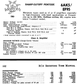
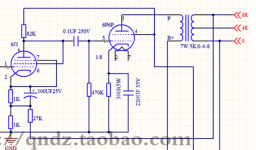
I have a bunch of 5654 tubes and some EL84's so would like to make an se triode amp using them. However, looking at this China circuit board which I bought and assembled, and sounds really good, the resistance values around the 5654 seem awfully high. Looks like a total of 2K for the cathode resistors when typically it seems around 470 ohms is normal. Measured voltage at the cathode is 3 volts, which I suppose is about right. The supply voltage to the plates of the 5654's is 225 volts with 20 volts dropped by the 82K plate resistor. Using ohms law that means the plate current is less than 1ma. This makes no sense to me.
Attachments
Can you measure DC voltages, put those on the schematic, and post that newly updated schematic? DC voltages would really help everyone understand what this circuit is actually doing.
Can you send more complete voltage readings?
What is the B+ to the 'top' of the output transformer secondary?
What is the voltage at the cathode of the output tube?
Are you using a 6P1P as the output tube, or something other than that?
What is the B+ to the 'top' of the output transformer secondary?
What is the voltage at the cathode of the output tube?
Are you using a 6P1P as the output tube, or something other than that?
Great, that all looks sensible.
It looks like the 6AK5 (6J1) is biased pretty cool. Plate current is only 1.5mA. The 6AK5 plate+screen current runs through both the 1k cathode bias resistor (bypassed by the 1000uF capacitor) and the 1k resistor 'below' that, to ground, which also is the bottom half of the voltage divider setting the level of NFB.
Granted the actual Ip+sg of the 6AK5 is actually a little less than 1.5mA because the (very) small amount of current through the NFB voltage divider adds to the Ip+sg of the 6AK5. But I think Ip+sg = 1.5mA is close enough.
This is the loadline I see for that 6AK5-triode input stage:

You could probably change the value of the 1k cathode bias resistor if you really want to. The NFB is set by the 27k/1k voltage divider, which operates outside of the 1k//1000uF cathode bias network. I'm not sure what that would accomplish, since the chosen operating point looks on the warm side of central on the loadline already, and you don't want to run the input stage into grid current prematurely.
I'd say unless you're motivated to redesign the amp for yourself, you might as well enjoy it as is. Unless, of course, you find it lacking in some way...
It looks like the 6AK5 (6J1) is biased pretty cool. Plate current is only 1.5mA. The 6AK5 plate+screen current runs through both the 1k cathode bias resistor (bypassed by the 1000uF capacitor) and the 1k resistor 'below' that, to ground, which also is the bottom half of the voltage divider setting the level of NFB.
Granted the actual Ip+sg of the 6AK5 is actually a little less than 1.5mA because the (very) small amount of current through the NFB voltage divider adds to the Ip+sg of the 6AK5. But I think Ip+sg = 1.5mA is close enough.
This is the loadline I see for that 6AK5-triode input stage:
You could probably change the value of the 1k cathode bias resistor if you really want to. The NFB is set by the 27k/1k voltage divider, which operates outside of the 1k//1000uF cathode bias network. I'm not sure what that would accomplish, since the chosen operating point looks on the warm side of central on the loadline already, and you don't want to run the input stage into grid current prematurely.
I'd say unless you're motivated to redesign the amp for yourself, you might as well enjoy it as is. Unless, of course, you find it lacking in some way...
rongon I've been messing with the value of that cathode bias resistor, changing it to 500 ohms instead of 1000. That reduces the bias to 2.5 volts which sounds more pleasant to me. Looks like that puts in in a more linear portion of the tube if I am not mistaken.
What I'm going to try now is to short out one of those two resistors - the one connected directly to the cathode. That should get some more current flowing and I'll see how it sounds.
Don't forget that biasing the input 6AK5 hotter means it will not be able to swing as many volts into the output tube and into the negative feedback loop.
With the 6AK5 biased the way it was stock, it can swing +/-60V peak, which is 5X the peak volts needed to drive the 6V6 to clipping. The remaining gain is available to drive the negative feedback loop, which means there's up to 14dB of NFB possible.
If you increase the bias from -3V to -2V on the 6AK5 cathode, the plate current only goes up by about 300uA. However, the available voltage swing from the 6AK5 plate is cut in half, to only +/-30V peak. That's now only 2.5X the peak volts needed to drive the 6V6 to full power, which means now there's only 8dB of NFB available.

I figure distortion from the 6AK5 due to grid current will become significant when the input signal swing drives the 6AK5 to about +0.5V on the cathode (-0.5V bias).
With the 6AK5 roughly center biased (blue line with arrows labeled "-3V") you can see that the grid voltage can swing -2.5V from -3V down to -0.5V.
But if you change the bias voltage to -2V, now the input can only swing -1.5V from -2V down to -0.5V. That is a significant reduction in available output signal voltage from the 6AK5-triode.
As you can see, you can increase the current through the 6AK5 by reducing the value of Rk, but that has consequences other than simply running the tube hotter. Have you spent much time drawing load lines for various triodes, to get a feeling for how changing Rp and Rk changes the available output swing and other characteristics of a triode stage?
This article explains this, but from a guitar amp perspective. Still useful for hi-fi.
https://robrobinette.com/Drawing_Tube_Load_Lines.htm
Norman Crowhurst wrote some of the classic texts on the subject, including this one:
http://www.triodeguy.com/Triodeguy PDF files/ch1.pdf
I hope that helps.
With the 6AK5 biased the way it was stock, it can swing +/-60V peak, which is 5X the peak volts needed to drive the 6V6 to clipping. The remaining gain is available to drive the negative feedback loop, which means there's up to 14dB of NFB possible.
If you increase the bias from -3V to -2V on the 6AK5 cathode, the plate current only goes up by about 300uA. However, the available voltage swing from the 6AK5 plate is cut in half, to only +/-30V peak. That's now only 2.5X the peak volts needed to drive the 6V6 to full power, which means now there's only 8dB of NFB available.
I figure distortion from the 6AK5 due to grid current will become significant when the input signal swing drives the 6AK5 to about +0.5V on the cathode (-0.5V bias).
With the 6AK5 roughly center biased (blue line with arrows labeled "-3V") you can see that the grid voltage can swing -2.5V from -3V down to -0.5V.
But if you change the bias voltage to -2V, now the input can only swing -1.5V from -2V down to -0.5V. That is a significant reduction in available output signal voltage from the 6AK5-triode.
As you can see, you can increase the current through the 6AK5 by reducing the value of Rk, but that has consequences other than simply running the tube hotter. Have you spent much time drawing load lines for various triodes, to get a feeling for how changing Rp and Rk changes the available output swing and other characteristics of a triode stage?
This article explains this, but from a guitar amp perspective. Still useful for hi-fi.
https://robrobinette.com/Drawing_Tube_Load_Lines.htm
Norman Crowhurst wrote some of the classic texts on the subject, including this one:
http://www.triodeguy.com/Triodeguy PDF files/ch1.pdf
I hope that helps.
Yes that is very helpful and very interesting. I was just about to touch the soldering iron to the board to remove one of those 1K resistors when I got a notification of your post, and now I think I'll just turn the iron off. LOL. Thank you again for all your help and education.
I'm happy to help.
If you could read up on the relationship between the plate load resistor (Rp) and cathode bias resistor (Rk) values and how they affect a triode given a particular B+ voltage, I think you'll see that there are lots of opportunities for tweaking with that amplifier you have. Just randomly changing resistor values and trying to listen for better/worse changes is helpful, but only to a point.
To simplify, there is a relationship between the triode in question (6AK5-triode), the value of Rp (82k in this circuit) and the value of Rk (2k ohms in this circuit).
You can get a feel for this by playing with this neat online loadline calculator:
https://www.vtadiy.com/loadline-calculators/loadline-calculator/
6J1 is in the list of available tubes, and you can set the tool to triode too.
A small error is creeping into the discussion. Long loop feedback doesn't add any burden to the driver's required anode voltage swing, which seems to be implied above. Maybe surprisingly the driving valve (also the output valve!) has the same grid-to-cathode drive voltage and the same anode output voltage swing with or without loop feedback. Neither valve even knows whether or not feedback is occurring.
All good fortune,
Chris
All good fortune,
Chris
I stand corrected!. (Thanks for pointing that out.) There's so much to learn, but that's the process. 🙂
Yes, thinking about it I realize that the negative feedback reduces the signal the input stage 'sees', therefore that stage does not need to be adjusted to provide more voltage swing headroom. The entire amp will be less sensitive because with 6dB of NFB (for instance) 1V at the input will be reduced to 0.5V (cut in half). I'm struggling to visualize exactly how that happens, but I'll keep working on it.
So... No matter what, the input stage needs to be able to swing 12V peak of audio signal into the 6V6 grid. It's common practice to allow +6dB of headroom there (double the voltage), therefore 24V peak (or as close as we can get).
The gain of the 6AK5-triode is about 25x (I think). So the 6AK5-triode grid bias needs to be at least -1V. That means 0.5V input signal should result in 12.5V to the 6V6 grid. Since a triode will typically begin to draw grid current with bias closer to 0V, we want to keep the grid bias more negative than -1V anyway. So it all works out nicely with a 6AK5-triode.
Right?
It might be useful to think about feedback amplifiers from the standpoint of a fixed output, rather than a fixed input. Working backwards from the speaker terminals, we would measure the same signal swing, with or without feedback, at the output terminals, at the output valve's anode, at its grid (therefore at the driving valve's anode) and at the difference between the driving valve's grid and cathode. These are all fixed in place by the characteristics of the valves and their working loadlines (which apply the same with or without feedback).
What changes is signal voltage at the driver's grid referenced to ground and at the driver's cathode referenced to ground. We would measure each of these increased by the same amount, the feedback voltage.
Sensitivity to grid current varies completely with source impedance. A perfectly stiff, zero impedance, source is indifferent to grid current loading and the valve will operate just like its published curves, even up into the positive grid voltage area. A high impedance source will introduce distortion as its load varies with grid current - it's trying to drive a diode. Folk will try to give advice about where exactly we need to begin to worry about bias voltage, but that varies with type, age and construction of a particular valve, and with source impedance. Small signal valves are usually considered "clean" enough with no greater than -1.0 VDC at peak signal swing and "average" (whatever that means) source impedance.
All good fortune,
Chris

- Home
- Amplifiers
- Tubes / Valves
- 6AK5, 5654 - EL84 Amp