I'm trying to create a reference-quality open source implementation of a relay bypass scheme. The idea is to have the "user interface" be a simple momentary SPST switch. A microcontroller will monitor momentary switch presses, and in turn send a current pulse to a latching relay to set or reset it. My particular use case is for an electric guitar effect pedal, i.e. stompbox, but I think the concepts apply to hifi designs as well (e.g. input selection on a preamp).
I actually asked about it here:
Should I protect against collapsing field effects of a microcontroller-driven small-signal relay coil?. To summarize, I'm using four IO pins of a small MCU (e.g. ATtiny13, ATtiny85, pic12f675, pic10f322): one as input to monitor the momentary switch, one output to turn a status indicator LED on or off, and two as outputs to drive a relay coil. I think I have a handle on the switch and status LED. But my question is what comes "between" the MCU and relay.
Currently, I'm looking at a single-coil latching 5V relay, like the Panasonic TQ2-L-5V. According to my read of the datasheet, a short (3ms) pulse of 20mA is required to drive the relay coil.
Right now, I have the MCU IO pins directly connected to the relay coil pins. This works for all four of the MCUs I mentioned above (I tested on a breadboard). And going from examples on the web, as well as one of the responses to my EE StackExchange question, it's a common practice. But most of the responses on that StackExchange post suggest it's one of those things that "works for now", but is a bad design, and could have unexpected results at some point in the future.
FWIW, this has been discussed a couple times already on this forum, and there is another, similar EE StackExchange question:
Grossly oversimplifying, but the common theme is: direct-connecting the MCU to the relay coil works, is easy, simple, low-part count. But it's not an ideal design, due to the IO pins being used as current sink/sources (especially considering voltage drop), and the effect of the high voltage spike (due to collapsing field effect of the coil) on the MCU IO pins.
Here's my MCU code, if you're interested: mcu-relay-controller on GitHub.
I actually asked about it here:
Should I protect against collapsing field effects of a microcontroller-driven small-signal relay coil?. To summarize, I'm using four IO pins of a small MCU (e.g. ATtiny13, ATtiny85, pic12f675, pic10f322): one as input to monitor the momentary switch, one output to turn a status indicator LED on or off, and two as outputs to drive a relay coil. I think I have a handle on the switch and status LED. But my question is what comes "between" the MCU and relay.
Currently, I'm looking at a single-coil latching 5V relay, like the Panasonic TQ2-L-5V. According to my read of the datasheet, a short (3ms) pulse of 20mA is required to drive the relay coil.
Right now, I have the MCU IO pins directly connected to the relay coil pins. This works for all four of the MCUs I mentioned above (I tested on a breadboard). And going from examples on the web, as well as one of the responses to my EE StackExchange question, it's a common practice. But most of the responses on that StackExchange post suggest it's one of those things that "works for now", but is a bad design, and could have unexpected results at some point in the future.
FWIW, this has been discussed a couple times already on this forum, and there is another, similar EE StackExchange question:
- diyAudio - Controlling a relay with a PIC microcontroller
- diyAudio - Protection diodes for various relay types?
- EE StackExchange - MCU to switch single coil latching relay not working (attempting array with common gnd)
Grossly oversimplifying, but the common theme is: direct-connecting the MCU to the relay coil works, is easy, simple, low-part count. But it's not an ideal design, due to the IO pins being used as current sink/sources (especially considering voltage drop), and the effect of the high voltage spike (due to collapsing field effect of the coil) on the MCU IO pins.
Here's my MCU code, if you're interested: mcu-relay-controller on GitHub.
Why not use a buffer transistor? Cheap and works fine.
You mean to to remove the current source/sink load from the MCU, right?
But won't the transistors need protection from the flyback effects of the relay coil?
That's what a flyback diode is for, and is routinely used.
https://resources.pcb.cadence.com/blog/2022-selecting-flyback-diodes-for-5v-relay-coil-suppression
https://resources.pcb.cadence.com/blog/2022-selecting-flyback-diodes-for-5v-relay-coil-suppression
Attachments

Its perfectly fine to do this so long as you are within the current capabilities of the pins (and the microcontroller as a whole), and protect from inductive kickback with diodes - this last is never optional with inductive loads, even small inductors can potentially output spikes of kilowatts of power without free-wheel diodes (millijoules released on sub-microsecond timescales = kilowatts available to fry things).
Some microcontrollers have fairly beefy outputs (25mA continuous or so), so paralleling them can be quite powerful, but you should parallel pins that are controlled by the same output register so they are all switched simulataneously (avoid them fighting each other).
Often the easiest way to drive a single-coil latching relay is with a small motor H-bridge - especially if you use one with in-built free-wheel diodes.
Using a microcontroller pins directly is a way to implement a small H-bridge with reduced parts count, but you need to realize the limitations of the output drivers in most microcontrollers.
Dual-coil latching relays are arguably easier to drive, a couple of transistors/FETs and free wheel diodes, extra parts, but simple and cheap.
So in @rayma's example above, that 1n4148 is used as the protection diode for the bc547, right? So when the coil's field collapses (i.e. after the current pulse), the momentary voltage spike will cause the diode to conduct, and put that temporary big voltage on the +12v rail (instead of the transistor).
But couldn't parts on the +12v rail possibly be damaged from that brief voltage spike? For example, that +12v rail likely has a bulk electrolytic capacitor on it. Aren't we just moving the problem around? Maybe we also need a small (1nF?) high voltage cap to ground on that 12v rail, since the high voltage spike will be short enough that the small cap can act like a short?
Side note: in researching this, it seems like I've typically seen Shottkey diodes used as the flyback protection diodes?
That's what I've been thinking. I'm having trouble figure out exactly how things would be arranged for the single coil case. But I think I have an idea what the dual-coil looks like. (Single coil relays appear to be slightly cheaper... not to mention, I already bought a bunch of them!)
But couldn't parts on the +12v rail possibly be damaged from that brief voltage spike? For example, that +12v rail likely has a bulk electrolytic capacitor on it. Aren't we just moving the problem around? Maybe we also need a small (1nF?) high voltage cap to ground on that 12v rail, since the high voltage spike will be short enough that the small cap can act like a short?
Side note: in researching this, it seems like I've typically seen Shottkey diodes used as the flyback protection diodes?
Dual-coil latching relays are arguably easier to drive, a couple of transistors/FETs and free wheel diodes, extra parts, but simple and cheap.
That's what I've been thinking. I'm having trouble figure out exactly how things would be arranged for the single coil case. But I think I have an idea what the dual-coil looks like. (Single coil relays appear to be slightly cheaper... not to mention, I already bought a bunch of them!)
Hi. When relay coil is turned off, voltage is removed , relay coil generates voltage spike of opposite polarity , and only then the mentioned diode will conduct, and that spike is limited to roughly 1V . So with 12v supply to relay transistor is getting close to 13v spike.So very simple and effective. Also in place of NPN you can use N-Mosfet like 2n7002.
For the single-coil relay, if I do something like this, are the protection diodes still necessary?

The MCU IO pins (ATTINY13_PB2 and PB3 in the schematic above) will be kept low. To change relay state, one MCU pin will go high temporarily, to give the relay coil a path to ground. After the current pulse to change relay state, the NPNs' bases will once again both be low, making the transistors look like an open circuit. So won't the flyback voltage go through the 0R resistors to the +5v supply?
In the 5v case, I would actually omit the 0R resistors. I put those there as a placeholder, thinking that I can actually use a 3v relay, and a 3v3 supply, and those resistors can drop the voltage a bit from 3v3 to 3v0.
(Here) is a little test I performed 3.5 years ago. With no flyback protection components whatsoever, I measured a flyback pulse magnitude of 600 volts across the coil of a 12V relay. But luckily you can buy very low cost relay driving transistors with insanely high max-VCE ratings, and this does not hurt them.
Or if you are super duper conservative, you can wear a belt and suspenders. Include flyback protection components AND use relay driving transistors with insanely high max-VCE ratings. Now you can sleep soundly.
Or if you are super duper conservative, you can wear a belt and suspenders. Include flyback protection components AND use relay driving transistors with insanely high max-VCE ratings. Now you can sleep soundly.
(Here) is a little test I performed 3.5 years ago. With no flyback protection components whatsoever, I measured a flyback pulse magnitude of 600 volts across the coil of a 12V relay. But luckily you can buy very low cost relay driving transistors with insanely high max-VCE ratings, and this does not hurt them.
Looks like they have power MOSFETs in TO-92 package, for example, ST STQ2LN60K3-AP (datasheet). Drain-source breakdown voltage of 600v. About twice the cost of a 2n3904, but not terribly expensive.
Or if you are super duper conservative, you can wear a belt and suspenders. Include flyback protection components AND use relay driving transistors with insanely high max-VCE ratings. Now you can sleep soundly.
In the schematic I posted above, for the super duper conservative design, are flyback protection diodes still needed? And where would they go?
I realized that schematic I posted will almost certainly not work! When only one transistor is turned on, current will flow almost entirely "straight down", as the path through the coil will have higher resistance. So little to no current will flow through the coil, certainly not enough to reliably activate the coil.
I think I'd need four total transistors to make this work, basically replacing those 0R resistors with transistors, and then it's obvious where the flyback protection diodes go.
I think I'd need four total transistors to make this work, basically replacing those 0R resistors with transistors, and then it's obvious where the flyback protection diodes go.
Your schenatic in post #8 will not work because 0 ohms resistors shorts the coil, and when you turn on any transistor, it will try short circuit power supply with know consequences. Because of this h bridge is designed, where 4 devices needed and additional circuitry to control them. Much more simple is relay with two coils .
The problem is such a high dV/dt voltage spike causes (very audible?) interference to nearby circuitry and may fail emissions tests. Much much better to provide free-wheel diodes so there is no voltage spike, the current just continues to circulate through the diode(s) and dies down slowly.(Here) is a little test I performed 3.5 years ago. With no flyback protection components whatsoever, I measured a flyback pulse magnitude of 600 volts across the coil of a 12V relay. But luckily you can buy very low cost relay driving transistors with insanely high max-VCE ratings, and this does not hurt them.
However sometimes you want the magnetic field to stop a bit faster (for mechanical reasons perhaps), in which case add a zener in series with the diode to clamp the voltage spike at some reasonable value thats significantly larger than a diode drop. Or you can use a resistor in series with the diode (with a suitable value resistor you can lose the diode and just waste a little power in the resistor).
Just connect a VVV volts zener diode (nothing in series with it -- no resistor, no PN junction diode, no nothing) across the switching transistor. If the relay coil actuates at XX volts, and the switching transistor is guaranteed to be reliable all the way up to VCE = YY volts, choose the zener voltage to be VVV = (0.9 * YY) volts. Presto your flyback protector design is exactly one component, which makes the bean counters happy. Large V therefore small delta_T { inductor equation: delta_T = (L * delta_I) / V } also means that the relay releases much sooner, as post #13 alludes.
Active clamping is used for fast demag.However sometimes you want the magnetic field to stop a bit faster (for mechanical reasons perhaps), in which case add a zener in series with the diode to clamp the voltage spike at some reasonable value thats significantly larger than a diode drop. Or you can use a resistor in series with the diode (with a suitable value resistor you can lose the diode and just waste a little power in the resistor).
Off topic...
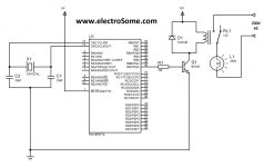
I implemented a IC 555 based latching relay driver, and I'm using a 12V relay module that has an opto-isolated input. It also has a freewheeling diode across the relay coil.
Should I add a zener in series to the free wheeling diode, or is it unnecessary?
The relay module is here.
I implemented a IC 555 based latching relay driver, and I'm using a 12V relay module that has an opto-isolated input. It also has a freewheeling diode across the relay coil.
Should I add a zener in series to the free wheeling diode, or is it unnecessary?
The relay module is here.
Off topic...
I implemented a IC 555 based latching relay driver, and I'm using a 12V relay module that has an opto-isolated input. It also has a freewheeling diode across the relay coil.
Should I add a zener in series to the free wheeling diode, or is it unnecessary?
No need.
If you use a cheap NPN transistor such as a 2N3904 and protect it with a cheap diode like the 1N4148 it works, as people have been doing forever, whether a single pull in relay or a latch relay. Latching just requires more parts. Attaching a schematic of a four input relay board with XLR and RCA connections for a preamp for you to see how it is typically done.
Attachments
- Home
- Source & Line
- Analog Line Level
- Microcontroller-driven latching relay