I am working on a fairly simple balanced line stage that will consist of a LTP driving a balanced source follower output stage. The LTP will use a discrete SS CCS in its tail and will be driven from a balanced source. My B+ is from a Maida regulator with about 250V output, and a regulated 6.3V DC heater supply. I could voltage double if the heater current is low enough. I also have a -20VDC low current regulated supply which I am planning to use for the CCS connection.
I am looking for a dual triode recommendation that is not too finicky (I'm a relative novice when it comes to tube circuit design) that will produce clean output with modest gain (2-3x optimal) and no global feedback. I was thinking of a 6SN7 or 12AU7.
I was also thinking I'd use some cathode degeneration to improve linearity, reduce the gain, and potentially to adjust balance (with a trim pot).
Thanks.
Aside from the source followers, I am running EL84 rigged as triodes. Cascode tail load, and a yoooooge B+ so I can run enough current through 20kOhm plate loads. Works also with EL86/6CW5.
Try a pair of 6AH4's...mu is about 8, delivered in circuit to each plate about 3.5. Or perhaps sort some 6BL7GTA for section-section match.
cheers,
Douglas
Try a pair of 6AH4's...mu is about 8, delivered in circuit to each plate about 3.5. Or perhaps sort some 6BL7GTA for section-section match.
cheers,
Douglas
@Bandersnatch - Thanks for the suggestions. A low mu tube is certainly worth considering, although I'm a bit concerned about the availability of the 6AH4. It doesn't appear like there is any new production, and NOS versions seem to be getting pretty scarce (although currently not expensive).
The 6BL7 also looks interesting, but I'm a bit concerned about the high heater current (and again, the limited availability) This would require some redesign of my power supply. I'll have to ponder this for a bit.
Since they are relatively inexpensive, I guess I could buy a few and see how well they test. Tube World Express is the only online dealer that seems to have any selection of 6AH4 - any experience with them? Do you have a favorite brand?
I did not find a notable difference between the 6AH4's I tried. There's plenty around; grab a six-pack and you'll be fine. I am sure Radio Electric Supply has 'em.
I did a PS from Mouser, and rigged the 12V supply with the two in series. It was like $15. 120VAC in, and the 12V DC out the other end.
Douglas
I did a PS from Mouser, and rigged the 12V supply with the two in series. It was like $15. 120VAC in, and the 12V DC out the other end.
Douglas
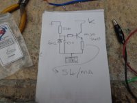
The ECC82, 12BH7A, 6CG7, 6SN7 all make decent LTP's. I usually use 47k anode R's with the CCS set to around 4mA ish (8mA total) Vk = 7 to 8v. I've attached a couple of CCS circuits I use though they might need tweaking at you have a lower negative rail.
Andy.
Andy.
Attachments
Also to consider if you wish balanced output, a SE voltage amp followed by a split load. The split load can be SS or tube. Type 12A4 will do a fine job, as will its lower mu brother the 12B4. Given the amount of voltage output you will want, they're probably interchangeable... ")
Douglas
Douglas
Thanks for all the suggestions. I've got some studying to do.
@Diabolical Artificer - your second CCS circuit is very similar to what I was planning, but I'm going to use LEDs for voltage references, and was looking at a 2N3904 for the lower transistor.
@Bandersnatch - I'm using both balanced inputs and outputs, so I was planning to feed the input directly to the LTP gates (through gate stoppers), and then connect the plates to CCS loaded source followers.
Don't leave out pentodes. Type 6AU6 is not to be despised. A dropping R from B+, with a common connection to both screens, and a bypass from g2 node to cathode node( 1 uF should do ) should get on your list. Figure g2 current to be *ABOUT 30% of plate current for dropping R calculations.
This approach allows adjustment of gain with plate load value...just remember to mind the dissipation rating, and adjust CCS current to deliver a decent operating point. Somewhere between 27 and 56k should do quite well.
Douglas
This approach allows adjustment of gain with plate load value...just remember to mind the dissipation rating, and adjust CCS current to deliver a decent operating point. Somewhere between 27 and 56k should do quite well.
Douglas
If you use a dual triode, and the signal to the input triodes is balanced/differential, you do not need a CCS in the cathode circuit.
Just use a single resistor, and no bypass capacitor (and that does not need a negative supply for the single resistor).
Example:
* Suppose a single ended triode input uses a 1k Ohm self bias resistor, and a bypass capacitor. The B+, plate load, and 1k Ohm cathode resistor gives you the quiescent voltages and currents you like.
Now, using that quiescent state of the single ended stage, you simply do the following:
Dual triode balanced input, connect the two cathodes together, and use a single 500 Ohm resistor. The quiescent parameters of each triode will be the same as for the single ended single triode stage above *.
Or, if you want to balance the two triodes plate current of less than well-balanced triodes, then use a 470 Ohm resistor, tie the wiper of a 100 Ohm potentiometer to the top of the 470 Ohms, and tie the ends of the potentiometer to the cathodes (cathodes not connected to each other, instead 100 Ohms away from each other).
The un-bypassed 100 Ohm will reduce the gain of the stage (you can get the lower gain you want, for example 400 Ohm resistor connected to the wiper of a 200 Ohm potentiometer gives less gain than the 100 Ohm pot and 470 Ohm resistor; and a 50 Ohm pot and 475 Ohm gives more gain).
My balanced amplifier input stage uses the following:
A shunt wired volume control (7 resistors for the 2 input grids including: XLR connector, 2 Rg to ground, 2 series resistors, a shunt rheostat, and 2 grid stopper resistors).
12AU7 cathodes are connected together, to a single 270 Ohm resistor to ground.
Two 27k plate load resistors.
The shunt volume control looses about 3dB from the XLR voltage, but the balanced/differential signal is 6V peak, 12V peak to peak.
Works for me!
Silicon parts?
Amplifier circuitry, No.
Power Supply, Yes.
Just my Opinion (and just my amplifiers)
Have fun designing, building, and listening!
Last edited:
A low value for the tail resistor will cause balance issues. A CCS in the tail is an artificial way to create better balance with a much lower voltage drop compared to a large resistor, leading to more gain and significantly better balance. I recommend reading Merlinb's articles on LTP and CCS:
http://valvewizard.co.uk/dcltp.html
http://valvewizard.co.uk/acltp.html
http://valvewizard.co.uk/ccs.html
http://valvewizard.co.uk/dcltp.html
http://valvewizard.co.uk/acltp.html
http://valvewizard.co.uk/ccs.html
pblix,
A pair of triodes in balanced configuration has Very Little 2nd harmonic distortion.
No CCS needed to reduce 2nd harmonic with balanced signals in.
I used a single un-bypassed resistor, and parallel cathodes.
I also used individual self bias resistors, and individual bypass resistors (can give slightly more gain, than the single resistor that is common to both cathodes)
Try it (I have).
In fact, a pair of balanced triodes with Either CCS long tail, Or 'high resistance/high negative voltage' long tail connection, often produces 3rd harmonic distortion.
Your Mileage May Vary.
Last edited:
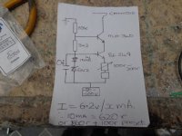
I prefer using a 6V2 zener because it gives a higher V ref than a LED so I can use a 500r Piher preset in order to make Ik adjustable. If you really want even better regulation use a CCS into the LED or zener. Sorry, winding up all the "sand" haters out there : ) 2N3904 Yep, any old Q will do though Morgan Jones in his book say s a Q with a higher hfe = a higher Z. Having said that I've used all sorts inc BD139's, 2N2907A's (in active loads), BC550;s, MPSA42/43 and of course the MJE340. doesn't seem to matter much.@Diabolical Artificer - your second CCS circuit is very similar to what I was planning, but I'm going to use LEDs for voltage references, and was looking at a 2N3904 for the lower transistor.
One thing I have found using a CCS/LTP combo is that the two Va differ by about 10v DC, this is less with a R as the tail, something to take into account if anything is direct coupled. One useful aspect of using a resistor in the tail is less gain, which may be desirable as others have noted.
Last edited:
I was shooting for a voltage gain of about 3x, but after looking at one of the amp projects I am working on, a bit higher gain would work well. My current primary amp has an balanced input impedance of 10K with 7M cables, so it needs a reasonable amount of drive. With my current amps (and planned projects), a maximum output voltage of 8V would suffice, but having a little more headroom wouldn't be bad.
I'm currently thinking of trying the 6N6P. I've got a bunch of these in my limited tube stash and it looks like it might work reasonable well. Attached is my current schematic. I'd appreciate any critique.

I'm currently thinking of trying the 6N6P. I've got a bunch of these in my limited tube stash and it looks like it might work reasonable well. Attached is my current schematic. I'd appreciate any critique.
First of all, you really don't need a high voltage MJE340 as Q2. Then, what do you intend with R22 and R23? To reduce gain, configuring each branch as an inverted amplifier with NFB from the output to the related input grid might be preferable, if the source impedance allows it.
Best regards!
Best regards!
Jaytor,
Your Post # 1 said: "I am working on a fairly simple balanced line stage".
I never thought the intent of the design question was to be able to produce a preamp that is this complex. Wow!
Make sure that all thse solid state devices quiescent operating points do not drift more than the tubes quescent operating points drift . . .
as the preamp warms up, and as the ambient temperatures change . . . winter to summer.
Is this for a commercially produced product?
If not, I have to ask what the rest of your home system components are . . .
Turntable, tone arm, moving coil cartridge, MC transformer, high end CD player, power amp mono-blocks, loudspeakers, room treatments, etc.
"You should make things as simple as possible, but no simpler." - Albert Einstein
Last edited:
- Home
- Amplifiers
- Tubes / Valves
- LTP Tube recommendations