For Sale Assembled Pit Viper Crossovers

Hey folks, I have some ready to crossovers for the Pit Viper speakers by Paul Carmody. The PCB's were made by Matt G (you all know the one, what a great guy). I made some modifications to my driver layout that unfortunately proved to be a little too much for the crossover and haven't had luck altering the xover parts to appease my layout.

I'll ship them to your door for $60.

20230622_183815.jpg

Hybrid RIAA tube preamp SS Poweramp General Arrangement

Hi,

Could someone please confirm what the big picture general arrangement to drive a pair of SS Icepower Monoblocks with a tube preamp from a turntable phono signal? Looking to only use tubes and no solid state up until the poweramp input. Assumption; SS Amp has 10K impedance so preamp requies <1K impedance.

Example 1. - Preffered but cannot find design
Phono MM or MC cartrige > Class A Single End Tube Preamp (impedance <1K) > SS Monoblocks (10K impedance)
Can anyone recommed any Class A Single End preamp designs with an impedance of less than 1k that accepts a RIAA input?

Example 2.
Phono MM or MC cartrige > RIAA Tube Preamp > SS Monoblocks
such as http://diyaudioprojects.com/Tubes/RIAA-Phono-Preamp/

Example 3.
Phono MM or MC cartrige > Tube RIA converter > Class A Single End Tube Preamp > SS Monoblocks
I found this design but I think it does not accept a RIAA phono input
https://www.cascadetubes.com/the-12au7-cathode-follower-color-preamp/

For Sale Some brand-new old stock aluminum electrolytic capacitors SMD

Hi All ! Long time to see.😆
1、315V 330uF 30x35mm 105C Snap In Capacitor Lelon LSK331M2F--A3035(50pcs)
https://www.ebay.com/itm/234973151726
2、50V 470uF 16x16.5mm SMD Capacitor Lelon VEJ471M1HTR-1616(200pcs)
https://www.ebay.com/itm/234976089271
3、25V 100uF 8x10mm SMD Capacitor Lelon VEJ101M1HTR-0810(500Pcs)
https://www.ebay.com/itm/234976105848

Zobel Network?

I'm not going to pretend that I really understand this subject, but I'm intrigued by the idea of Zobel networks and would like to learn if it would improve my speakers, which are currently leaning toward a harsh top end.
They are small T-M-M towers, with the 25mm silk dome CSS LD25x XBL tweeter above a pair of CSS LDW7 7" midwoofers, crossed at 1800Hz. Crossovers have good quality components by Erse and Jantzen.
Actual construction of a Zobel network seems pretty simple, but I don't really understand how to design one that's right for my speakers. Can anyone help?
Thanks!

Ideas for horn subwoofer (B&C 12PS32)

Hello everyone!.. i have this driver (b&c ps32) and i am thinking of building a sub ,specifically a horn type. I have built mth30s in the past, with great results, using ps32's smaller ''brothers'' the pz32's. I have seen martinsson's roar 12 sub plan, i find this very interesting design. I have done some reading and it seems that this design have some opposers , maybe it needs sove development maybe not, so it can reach the success of the mth30 or the tham 12, tham 15. I am open to ideas of course, since this site is a huge tank of knowledge with people that they really love what they do. thanks in advance and KEEP BUILDING....
12ps32-8_1.jpg

No more blue glow in Australia

I am writing this for the benefit of any Australians using this forum. It is now illegal to own sell mercury vapour tubes including 866 and 83 rectifier tubes in Australia. Included is a picture of a tube I handed in today, 17 tubes were sent to Northern Adelaide Waste Management, many of the tubes were brand new. Also included is a notice from a radio club magazine.
ug scale.jpg

mercury b.png

FS PCB clearance: Headphone Amps, D-Noizator PSU, MOD output delay, Ground Isolator..

I have a few spare PCB's. These are extra boards which I have left over from a fabrication run (due to minimum order requirements) and are therefore sold for DIY purposes only and not for commercial gain. They are to cover board, build and shipping costs to me, not for profit. Once they are gone, they are gone.

PAYMENT AND SHIPPING:
  • Payment by Paypal "Friends and Family".
  • UK - Free untracked P&P for orders over £5, additional fee for Signed-For.
  • EU / USA / Rest Of World - As per Royal Mail: Get a price | Royal Mail Group Ltd, additional fee for tracked.
  • Payment within 48 hours before being released from reserve.
  • Please reply here followed by a pm if interested.


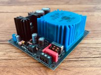
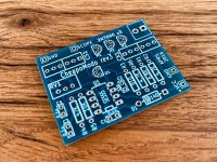
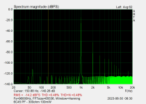
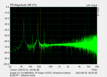
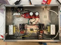
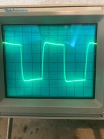
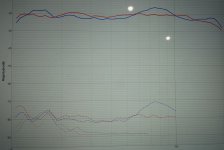
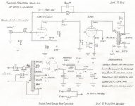
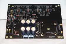
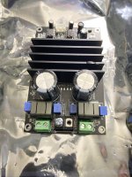
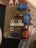
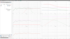
Die-Noizator 5-36V Linear PSU, PCB designed by me, schematic by Elvee/diegomj1973
D-Noizator: a magic active noise canceller to retrofit & upgrade any 317-based V.Reg.
Single rail positive PSU 5-36V.
Onboard transformer solution (Talema/Amveco/RS Pro toroidal series).
EMI filter, transformer snubber, CRC, LM317, Sziklai Pair Die-Noizator. Extremely low noise PSU.
These are my latest revision (2.1) with compatibility with 110V or 240V mains voltage.
Transformer secondaries can be jumpered parallel or series.
None available £7 each, 100g 'Letter'
  • 2x kcom00 (AUS) Dispatched 20th August
  • 2x jimk04 (UK) Dispatched 20th August
  • 2x mgb1965 (GER) Dispatched 20th August
  • 1x sq225917 (UK) Dispatched 7th September
  • 1x Mituisho (UK) Dispatched 13th September

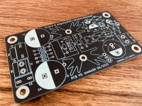
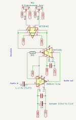
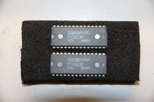
Die-Noizator 5-36V, PCB designed by tombo56, schematic by Elvee/diegomj1973
D-Noizator: a magic active noise canceller to retrofit & upgrade any 317-based V.Reg.
Single rail positive PSU 5-36V
Offboard transformer.
None available £4 each, 100g 'Letter'
  • 2x kcom00 (AUS) Dispatched 20th August
  • 1x kffern (AUS) Dispatched 20th August

Objective 2 Headphone Amplifier designed by NwAvGuy
NwAvGuy: O2 Details
7x available £8 each, 100g 'Letter'


Passlabs ACP+ Headphone / Pre-Amplifier Clone, PCB designed by withmatt
Amp Camp Pre+Headphone Amp - ACP+
None available- £12 each, 200g 'Letter'
  • 1x mgb1965 (GER) Dispatched 20th August
  • 1x Peppe (SWE) Dispatched 1st September
  • 1x Piisami (FIN) Dispatched 1st September
  • 1x M_Balou (GER) Dispatched 1st September

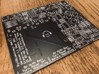
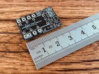
MOD: Mini Output Delay for Headphone / Line-level Audio designed by me
MOD: Mini Output Delay - a headphone / line-level audio output delay retrofit PCB
A miniature 2x3cm retrofit board to protect headphones from turn-on/off power transients.
12-35V power input. 0-30 seconds adjustable delay time.
10+ available £4 each, 100g 'Letter'
  • 2x mgb1965 (GER) Dispatched 20th August
  • 2x Gregje (UK) Dispatched 10th September
  • 2x Mituisho (UK) Dispatched 13th September
  • 2x SigFire (GER) Dispatched 21st September
  • 4x s666foto (NED) Awaiting Payment

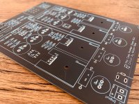
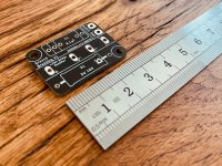
Ground Breaking: Earth Loop / Audio Ground Isolator designed by me
A 2x3cm board that helps reduce hum in audio circuits that are attached to a mains earth connection.
x5 available £3 each, 100g 'Letter'
  • 2x kcom00 (AUS) Dispatched 20th August
  • 5x truepaul (USA) Dispatched 26th August
  • 2x Neat Ripple (UK) Dispatched 28th August
  • 2x Slinkymalinky (UK) Dispatched 4th September
  • 2x avinunca (UK) Dispatched 5th September
  • 2x sq225917 (UK) Dispatched 7th September
  • 2x Mituisho (UK) Dispatched 13th September
  • 2x SigFire (GER) Dispatched 21st September

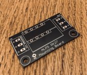
Alps RK27 Blue Velvet Breakout / Mounting Board designed by Nisbeth
A breakout board for mounting Alps RK27 volume potentiometer.
10+ available £3 each, 100g 'Letter'
  • 2x Neat Ripple (UK) Dispatched 28th August

8-Pin SOIC or MSOP/(T)SSOP to DIP Adapter
A miniature board to mount SOIC or MSOP/(T)SSOP integrated chips into DIP sockets. Perfect for op-amp rolling.
10+ available £2 each, 100g 'Letter'
  • 2x mgb1965 (GER) Dispatched 20th August

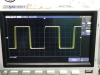
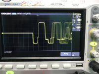
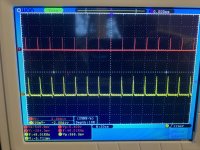
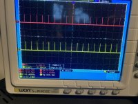
CheapModo Snubber Calculator designed by Mark Johnson
CheapoModo: quick and dirty transformer snubber bellringer jig
A quick and dirty transformer snubber bellringer jig to calculate optimum snubber resistance values.
None available £4 each, 100g 'Letter'
  • 1x kcom00 (AUS) Dispatched 20th August
  • 1x M_Balou (GER) Dispatched 1st September

Attachments

  • IMG_7980.jpg
    IMG_7980.jpg
    1,005.2 KB · Views: 929
  • IMG_8011.jpg
    IMG_8011.jpg
    816 KB · Views: 904
  • IMG_7982.jpg
    IMG_7982.jpg
    990.8 KB · Views: 887
  • PCB-O2.jpg
    PCB-O2.jpg
    989.7 KB · Views: 864
  • IMG_7984.jpg
    IMG_7984.jpg
    886.3 KB · Views: 832
  • IMG_7995.jpg
    IMG_7995.jpg
    813.3 KB · Views: 302
  • IMG_7986.jpg
    IMG_7986.jpg
    945.5 KB · Views: 290
  • PCB-RK27.jpg
    PCB-RK27.jpg
    638.1 KB · Views: 301
  • IMG_7991.jpg
    IMG_7991.jpg
    459.2 KB · Views: 306
  • IMG_7997.jpg
    IMG_7997.jpg
    957.3 KB · Views: 299

OB mono

...any of you use a mono OB speaker in your regular system? How do you think it compares to stereo OB or stereo box speakers?
I want to build a speaker similar to Reflector Audio P18 (but with a coax in place of the 2" compression driver). Two of those and the associated active amps and cabling would be unbearable in the living room. But just one is doable 🙂🙂🙂

Attachments

  • images.jpeg
    images.jpeg
    27 KB · Views: 66

mid/bass driver with dual voice coil?

I'm pretty new to higher end stuff 🙂 I have a pair of Energy Veritas 2.2 which have dual voice coils in each 6.5" woofer. The woofer is 3db down at 40hz (ported cabinet) and crosses over to a 2" aluminum dome midrange at 550hz. They are pretty transparent in the mids (edit: including the lower midrange spectrum that's covered by the woofer).

I'm planning on running them with a servo sub, crossed over at 80-85hz. The two voice coils are connected internally, so there are two wires brought out to connect to the crossover. Dual voice coils are supposed to help lower distortion at low frequencies and are used in some subs. I've seen dual VC midrange units for high power car audio, but I haven't found anything yet in the mid-high end audiophile market.

Here are a few details in a review of the Veritas 2.4 (3 of these mid/woofer units) from https://www.soundandvision.com/content/energy-veritas-v24-surround-speaker-system:

"The Veritas V2.4's 6.5-inch woofers have dual voice coils wound in opposite directions (thus the designation Dual-Hyperdrive). Each coil is situated in its own magnetic gap; operating them in tandem is said to significantly reduce distortion. The cone is made of a special composition designed to optimize weight, stiffness, and damping. A phase plug of solid aluminum eliminates the dustcap—a possible source of coloration—and helps dissipate heat."

So would a dual voice coil setup also improve the accuracy of the lower midrange? Or is it just mainly for the bass region?

For Sale Transformers!

Cleaning out the shelves:

2x Power tranformers: Prim 115/230, sec1 300-0-300, 300ma / sec 2 5v, 3A / sec 2 6.4V 4A. SOLD
2x PP Output transformers for EL34/6l6, 30W, 5k6 into 16/8/4ohm. Brand unknown. SOLD
2x Amroh U72 SE output tranformers. 5k,7k into 5/3.5/2.5 ohm, max 80ma,SOLD
2x Interstage transformers, 1+1:1+1, no further info, 60€/pair
2x input transformers, 0-30-ct-250-600 into 10k-0-10k, can be used as input transformer or totem step up or step down, 60€/pair
6x Toroidy transformers: All 20VA/ 2x 11V, 1x11V, 2x 25V, 2x18V, 2x11V, 2x15V SOLD
2x Sowter 4652 Line output transformers, 150+150:150+150, SOLD
9x pairs of input/mic transformers, some info included, make me an offer!

Will ship worldwide

Attachments

  • IMG_3300.jpeg
    IMG_3300.jpeg
    296.8 KB · Views: 141
  • IMG_3301.jpeg
    IMG_3301.jpeg
    286.4 KB · Views: 143
  • IMG_3302.jpeg
    IMG_3302.jpeg
    352.3 KB · Views: 131
  • IMG_3303.jpeg
    IMG_3303.jpeg
    411.9 KB · Views: 130
  • IMG_3304.jpeg
    IMG_3304.jpeg
    237.8 KB · Views: 189
  • IMG_3305.jpeg
    IMG_3305.jpeg
    595.2 KB · Views: 210
  • IMG_3306.jpeg
    IMG_3306.jpeg
    412 KB · Views: 205
  • IMG_3307.jpeg
    IMG_3307.jpeg
    382.6 KB · Views: 165
  • IMG_3308.jpeg
    IMG_3308.jpeg
    587 KB · Views: 172
  • IMG_3312.jpeg
    IMG_3312.jpeg
    567.2 KB · Views: 154
  • IMG_3313.jpeg
    IMG_3313.jpeg
    494.7 KB · Views: 141
  • IMG_3314.jpeg
    IMG_3314.jpeg
    588.7 KB · Views: 151

What’s this Amps 8 ohm RMS? Help

8CE57182-369E-44A3-8C39-1976682C3397.jpeg

I got this amp it’s says 1200w Max blah blah…

The actual rms is 2x

200w for 2omhs

I got a sub coming that’s 200rms 400max
It should be fine, the amp got 2 speaker outputs and it’s 2-16omh amp, could I run my sub from one speaker output and my 4x30rms watt 3way coaxial 4omhs speakers from the second channel?

Running the coxial speakers at 8omhs will make them take 60rms, just not sure can’t find the amps 8omh load rms but am guessing from the image above it’s somewhere 70watt at 8omh

Please correct me if am wrong

This is for home project I already am running my coxial speakers with a cheap amp.

Could I have blown a channel?

Hi All, been installing an Audison F8.9 DSP/Amp into a car and had to tap into the output/speaker cables of the OEM amp, to feed to the DSP, and all went well until replacing the factory OEM speakers, when i realised the wiring was different colours at the speakers compared to what i had tapped into at the OEM Amp side.

I had the negative battery terminal removed, and the speaker output plug removed from the OEM amp, and checked continuity between the speaker wires at the doors and the wires i had tapped into at the OEM amp side, to establish what colours at the OEM amp side were connected to what colours at the OEM speaker end.

However i was getting some strange readings, as was getting continuity tones from more than one set of speaker wires, and then i realised that I still had the speaker output cables plug leading from the DSP/amp still connected, i therefore removed that and all was fine with continuity as you would expect, with continuity only on one wire at the speaker and one wire at the OEM amp side, therefore it must have been the DSP internal circuity that was causing the strange readings/continuity on more than one set of speaker wires.

Anyway, my question is, even though i was checking continuity between the speaker wires at the OEM amp side and door speaker wires, because i still had the speaker output plug connected at the DSP/Amp, could i have blown a channel whilst checking continuity on those speaker wire outputs whilst they were still connected to the DSP? As essentially i've sent voltage up the output line?

Sony STR-6045 Diagnostic - help needed

Hi guys,

Lately, I have developed some interest in electronic repair and fixed a Celestion Ditton 662. But I wanted to learn more and my current project is now a small amplifier from the 70's, the Sony STR-6045.

When I purchased it, it had no power and a blown fuse on the Power Supply Board (a soldered one). I took the following steps to resolve the problem and I have some newb questions that I hope won't generate too many responses like "if you don't know electronic, hire a professional or go take some lessons online first". This is a hobby, I just want to learn.

1. I verified every components on the PSU board by unsoldering the necessary legs and measured resistors, diodes, capacitors and transistors. All were good except a 47uf capacitor that was 34% over specification. Any way, I changed the 3 electrolytics since there were not many and they were so old.

Question 1: The service manual seems to indicate that electrolytic capacitors can be 100% over specification. Is this normal and true?
Sony_STR-6045_capacitors_tolerance.png


2. I also cleaned the board heavily with alcohol and acetone as it seems to have oxidation or flux that were never cleaned up.
PSU_Board_Conductor_side.png


3. While everything was disconnected, I measured the voltage at the secondary terminals of the power transformer: 54.6 vac.
Question 2, is this normal for such and amp? The service manual does not specify what it is.

Sony_STR-6045_specifications.png


3. I put it back together and powered on the system (using a dim-bulb tester). Got a big shiny lamp. Half success. My diy current limiter is working but the amp is still not!

4. I then disconnected all wire except those going to the power transformer. And this time no light. And I then tried to measure the voltage as shown on the service manual.
Very stupid Question 3: How do I do this? I tried to clip the black prob to the chassis and to prob with the red one at the indicated points. I could not get any significant voltage.
Sony STR-6045 PS Board - Components Side.png

Sony STR-6045 PS Board - Conductor Side.png


5. Because there was no short when the power amplifier board was disconnected, I thought the problem was further down on the power amplifier board. But while trying to measure voltage it started to make smoke! R806 being super hot.
Question 4: Is it because I should have left the connections to the filter capacitors or is there a problem with the board I have repaired?

The full service manual is available online at many places (here for instance) for those interested although the scan is of poor quality. Here is an excerpt of the schematic diagram - power sections.

sony_str-6045_sm_power_sections_200percent.png


Thank you all in advance for your valuable advises.

Field Coil vs Ferrite Magnet sound

Hi All,
Ever since I started fiddling with FR speakers, I've been reading on how good FC FR sounds
& this has gotten me very curious. Like SET Amps, FC speakers are also from yesteryears.
Yes I understand the principals of how FC works & their flexibility in the adjustment of magnectic
strenght which offcourse would affect it sound production. My question is what if we adjust the
magnetic strenght of the FC to equal that of a same speaker but with Ferrite magnet instead, will
the FC still sound better & if so would it be due to coil design etc ?
By going FC this opens another can of worms which I've read the PS is very important to SQ as well,
so what is the proper type of PS is used to attain optimum results assuming that FC speakers are low voltage
version.

Many thanks

  • Locked
Help with hum in parafeed headphone amplifier

I recently completed a build of a Parafeed headphone amplifier, and have some hum that I would like to try and resolve.
There is a fairly long thread where I explored various options for a 5842 based amps but ended up with a 6C45Π similar to the Bottlehead Mainline and/or Papa Rusa.

The circuit is pretty much the Papa Rusa, with the exception of using the DN2540N5 cascade CCS from SY's ImPasse/HMN designs, and paying some more attention to the AC heater wiring such as elevating to 50V above ground, using a 1nF ceramic cap to chassis and tying each node though a ~100ohm resistor.
The PSU is 220uF - 5H - 220uF. There is a 1kΩ + 1nF snubbers for the transformer secondary.

There is low (but audible) hum when there is no signal. Based on FFT, it is 60Hz and 180Hz (with lesser of 120Hz and 300Hz)
When there is signal, even fairly low amplitude, the 60Hz drops, so its not audible when music is playing, but I'd like to try and get it to a completely quiet background.
I also looked at it with a scope with a 10khz square wave and there doesn't seem to be any oscillation. The tilt of the sq. wave aligns with the FR measurement from ARTA (HF boost), but I am fairly novice when it comes to interpreting this.

The attachments are FFT at 0 output, 5mW and 100mW, and FR at 0 output and 5mW output.

Any ideas where to look?
I'm also curious to understand why the 60Hz component drops when there is signal.

Thanks!

Attachments

  • 6C45 - 300ohm - 0mW.png
    6C45 - 300ohm - 0mW.png
    19.5 KB · Views: 88
  • 6C45 - 300ohm - 5mW.png
    6C45 - 300ohm - 5mW.png
    18.6 KB · Views: 82
  • 6C45 - 300ohm - 100mW.png
    6C45 - 300ohm - 100mW.png
    18.2 KB · Views: 85
  • 6C45 - 300ohm - FR - 0mW.png
    6C45 - 300ohm - FR - 0mW.png
    20.2 KB · Views: 81
  • 6C45 - 300ohm - FR - 5mW.png
    6C45 - 300ohm - FR - 5mW.png
    17.2 KB · Views: 106
  • 2023-06-29 15.23.05 (edited).jpg
    2023-06-29 15.23.05 (edited).jpg
    575.5 KB · Views: 100
  • JX2gTExY.jpeg
    JX2gTExY.jpeg
    355.2 KB · Views: 113

FS: Lot of drivers FE83NV, W200, 10FE200, Peerless Middomes; Audax PR240; Oberton 10M150; B&C 320K/C etc.

Selling the following:

Lot of various drivers in single listing -- Faital FE83NV Pair, Visaton W200 Pair, Faital 10FE200 single, Peerless Middomes: https://www.ebay.com/itm/275893316036

Audax PR240M0 8ohm 10" Sub woofer / Woofer Single: https://www.ebay.com/itm/275893307765

Oberton 10M150 8ohm 10" Midbass Bass Speaker: https://www.ebay.com/itm/275893297252

B&C 320K/C-A 8ohm 12" Bicone woofer: https://www.ebay.com/itm/275893304981

ChatGPT designed a gain cell - your comments?

LOL, so I got this apparently stupid idea to only do what ChatGPT suggested, I was not allowed (my own rules) to modify or add anything that ChatGPT did not suggest or recommended. The reason for saying apparently stupid is that I think it took about 3 weeks, on and off. The below description does of cause not contain all the tedious work it was to get it to understand what I wanted, sort out its many errors (talking about shielding where it suggested a garden fence because it shields for the wind). 🙂

Here is what I asked for and why it may look as it does.
1) Sound quality is most important.
2) Analog all the way. (just to avoid the usual digital volume control)
3) Possibility for adjusting the volume without ever using a pot.
4) Sound degradation is not allowed due to mechanical wear.
5) Everything has to work at the same voltage (It ended being +/-18VDC).

I started out asking for an op-amp, and it started by suggesting the OPA627, that I accepted but still did I ask about if it was the best, just to see how it reacted, it ended up in ChatGPT suggested a discreet solution and yes that is of cause a better solution, but I did simply not dare to begin letting ChatGPT guide me through a design of a discrete op-amp. (lol, my sanity is too valuable for that.) So I asked if there were some ready build op-amps, and it ended suggesting Sonic Labs 990Enh-Ticha that I have never heard off but hay it has great marketing.

Now to a way to adjust the volume and I asked it for a solution, again did several digital solutions come up, but I reminded the AI about the 100% analog solution. Then did it suggest using a FET, a combination of LED and LDR, or a gain cell solution. As you properly can read from the title did, I chose the gain cell to see how it would turn out.

To adjust gain did the AI suggest using a pot, but I reminded it about the possibility for adjusting the volume without any pot, and it got the AI to suggest a resistor of unknown value and a VCR in the feedback, but it was fairly limited what it could find and finally did it suggest a THT THAT2181.

Lastly after the AI had talked about using a pot for the 879th time did I ask how it would implement a pot, thinking of my rules about sound quality and wear, it had two suggestions, one was to get the best most expensive pot I could get or placing a buffer between the pot and the VCR, so I tried.

The result do you see below. It looks very strange, but this is how ChatGPT would have me build it.
Any comment? 🙂

Attachments

  • gain cell.png
    gain cell.png
    11.9 KB · Views: 392

JL Audio E6450 Q1 &Q2 part numbers

Hello guys, working on an E6450 with burnt P/S FETs. Found transistors Q1 and Q2 in the driver circuit are blown. The part number starts with PN, but can’t make out the complete part number. Anyone knows the correct part number? Thanks

Attachments

  • 406352C3-F68D-45C1-A4ED-F77E81970552.jpeg
    406352C3-F68D-45C1-A4ED-F77E81970552.jpeg
    722.2 KB · Views: 86
  • 1BFBA1FA-6CBB-459E-89D9-C5871AC7F57C.jpeg
    1BFBA1FA-6CBB-459E-89D9-C5871AC7F57C.jpeg
    520.8 KB · Views: 84

Wharfdale Centre 8 - 5" kevlar speaker specs

Hi

I have a Wharfdale Center 8 with the yellow 5" kevlar woofers and I was wondering if anyone has either in thier possession or a link to, the mechanical and electrical specs for these drivers, I was wanting to repurpise them into a 3 way speaker project and need specs to design an enclosure.

I've done some Web searches and come up with nothing.

The other option is to take the existing box, which is single ported and split it into two enclosures, how can this be calculated and achieved?

Adam

Acoustical notch filter for TPL-150

TPL 150 in dipole the 2º harmonic distortion drops 20dB, but have a big peak in the 8kHz range frequency response.

You can see in this tread:

https://www.diyaudio.com/forums/multi-way/142015-baffle-dipole-beyma-tpl-150-a-9.html#post1993491

You can see in the green impulse response a double oscillation. The period coincides approximately with 8 Khz. peak.

8 Khz. Wavelength 4,3 cm. Time period 0,13 ms.

A notch filter R // L // C in series corrects the 8 Khz peak response, but not these small impulse oscillations, in addition you have a peak in the impedance just at 8 Khz.

Acustical 8 Khz notch filter can corrects these small oscillations. You can see in red impulse with acustical filter. And the 8 Khz peak also in red in frequency response, in addition you don't have an 8 Khz peak in the impedance. And better harmonic distortion

I am going to summarize the steps that I have taken to obtain it.

The first clue is 1,1 cm. the 1/4 of the 8 Khz. Wavelength.

TPL-150 impulse response.
Green only dipole. Red with acustical notch filter.

872212d1598880028-acustical-notch-filter-tpl-150-a-q1a-jpg


TPL-150 frequency response
Green only dipole. Red with acustical notch filter.

872213d1598880028-acustical-notch-filter-tpl-150-a-q1b-jpeg

Attachments

  • q1a.jpg
    q1a.jpg
    330.6 KB · Views: 2,765
  • q1b.jpeg
    q1b.jpeg
    238.3 KB · Views: 2,777
  • Like
Reactions: vemsom

For Sale Burr Brown PCM63P-K DAC D/A Converter IC Pair NOS Genuine Korea

I have 2 PCM63P-K available. They have never been used or soldered in any way except that I did insert them in a DAC but never powered it up as I was going to do some other mods to it and never got around to it. I used to do warranty work for ADCOM, Parasound, and Behringer so I know they are genuine NOS. $120 plus shipping; PayPal only.

Sold "as-is" and no warranty is expressed or implied. No returns or refunds. Sells and ships to USA residents only.

Attachments

  • IMG_4668.JPG
    IMG_4668.JPG
    376.5 KB · Views: 119

Pioneer SA-5500 MK11

Hi


This HiFi amplifier uses two PA3002 power ICs for its L & R output and both have blown. This part is totally obselete. On checking on the net, as a replacement UPC1188H they say,can be used as a substitute. I replace both sides with this part. Now the problem I face is, when I turn on the amp, there is a loud hum but no audio and then if I turn the volume or bass up, the sound comes on but goes off, then comes on again and fades off. This keeps repeating and if I touch the chassis, the hums fades but comes on again. Is this a problem with the replacement IC or a power supply problem. The voltages to pin 3(+vcc) is +21V and pin10(-vcc) is -21V which is correct.


Thanks

KRK Rokit 5 2nd gen low bass

Hello,
I have a KRK rokit 5 2nd gen , recaped with low ESR nichicon, replaced a few 104 caps and resistors with correct values.
The speaker works but the bass is very low and the high from the twitter is really high .
did the same with the other one and it worked fine , same parts used .
where can I start checking ?
No more black junk, I cleaned it all up and re did all the corded connections with new ones .
Any help would be appreciated.
Thanks

Effects of low voltage to rectifier tube

I'm working on my first direct from schematic build (see below) and have a power supply related question for Asano/LW.

I plan to use a Hashimoto PT-160 power transformer with the following specs:

P.120V​
S.320V-280V-0-280V-320V AC140mA​
0-2.5V-6.3V 3A 2 circuits​
6.3V 2.5A​
5V 3A​
I should note that I plan to use a 5V4G in place of the 83V as a rectifier; however, the current schematic is asking for 380V and my transformer only outputs 320V. I'm curious to know - for this project and moving forward - what effects this lower voltage will have on rectification and if there are any adjustments I need to make down stream in the power supply. Perhaps there is a better rectifier tube choice...

That said, is there anything I need to consider in the PS when adding a second channel for a stereo configuration. Seems pretty straightforward, but figured I'd ask.

Many thanks in advance!
Jonah

Attachments

  • asano_loftin_white.jpg.html.jpeg
    asano_loftin_white.jpg.html.jpeg
    44.1 KB · Views: 351

McGee Radio Speaker Catalog - 1982

In 1982 I was 13 years old and in the hunt for a good pair of speakers. I had 20 watt Pioneer stereo receiver and was salivating over the Boston Acoustics A60s. But at $200 a pair they were well out of my reach.McGee1982_cover_M.jpg

I asked a stereo salesman about building speakers. He told me to write to McGee Radio and request their speaker catalog. I remember the December afternoon when I came home from school and the catalog had arrived.

(PDF of the catalog is here: www.tinyurl.com/mcgee1982)

A few weeks later I mailed ‘em a check for $82, which got me a Peerless TP165F 6.5” woofer and Tonegen T011-020-0 Tweeter, the same unit Boston Acoustics used in their A60. (Both of these drivers are pictured on the front cover.) I built an ugly but quite functional set of speakers that sounded just as good as the Boston A60s.

By the time I was 17, I was selling my speakers to friends and advertising my biz in the newspaper. Then I got a distribution agreement with a dealer in Lincoln Nebraska, Sound Dimensions, who started selling my “Acoustic Design Ltd” brand next to KEF, Denon and B&W.

When I was 23 I moved to Chicago and worked for Jensen for 3 years where I designed OEM speakers for Honda, Mazda, Ford, Chrysler and Acura.

In 2022, speaker design is back to being a hobby; here is one of my recent designs:

https://www.diyaudio.com/community/threads/ultimate-open-baffle-gallery.123512/post-6682515

The McGee catalog was terrible by today’s standards... it told you all kinds of irrelevant information (like the flux density of the magnets) but almost no specs you actually needed to know, like SPL or Qts. I’m not even sure the people who ran the place really knew that much how to design a speaker.

Nevertheless this humble catalog was where I got my start. Huge fodder for my teenage imagination. Even today I still enjoy flipping through this catalog and asking myself the question, “If you were ONLY allowed to source these 1982 components, what could you build then if you knew what you know now and had the tools you have today?”

Did anybody else buy stuff from McGee Radio in Kansas City?

Catalog: www.tinyurl.com/mcgee1982

Tube models & LTspice, trouble with (odd simulation behavior)

Hello, totally new here. I have some experience with LTspice, but not with these tube models (2 of the "Ayumi_LTspice", contained in the zip).

Could someone with experience tell me why this simulates so poorly (takes ages), and the crazy behavior when I actually attach the "HV" output label to the left end of R15 (it's disconnected in the attached schematic) - i.e. instead of the +366V I'm seeing a large negative voltage, as if the tube circuits do some black magick there.

Notes apart from that: the outupt transformer model may be crap, it's after measurements with an ebay LCR meter on a transformer I have laying around, but the L2 winding seems awfully low in series R and inductance - then again I have no other output transformer to compare to. Also, the power source is not as in the orig schematic, it's the supposed output of some cheap power transformer from a tube radio I just "shot" on ebay, arrival pending.

Attachments

Fender Princeton 65 DSP amp intermittent popping - any ideas?

Picked up a little Fender Princeton 65 DSP for gigging, really clean sound (had to replace the driver after my second gig as it has blown though!)

Recently it’s been ‘intermittently popping’. I’ve left it sitting whilst on, not touching a thing or shaking it, and it randomly pops a few times every few minutes or so. 99% certain this happens post the ‘PWR IN’ jack - any ideas what it could be?

Schematic can be found here: https://www.manualslib.com/manual/1183721/Fender-Princeton-65-Dsp.html?page=13#manual

help a newbie with 3 way crossover design

Hello! Im not a big Hi Fi audio person, so sorry if these questions are stupid 🙂

Anyways, I need to design a setup. The setup in question has a Woofer (4.5 ohms where I need it to crossover), a midrange speaker (10 ohms where I need it to cross over), and a tweeter (6.5 ohms where I need it to cross over). One of the speakers (the woofer) has a hump between 300-600 hz, so I need to begin my decent for the crossover before that. For the lower range of the mid, the crossover should be at 600 hz. I would like to use a 2nd order butterworth for all of this with a Q of 0.707.

the higher end is slightly more standard, however, I think i need to use an LPAD filter, because the efficiency of the tweeter is around 6db higher than that of the woofer.

Im starting to design the situation in spice. I have attached what I have so far.
unnamed.png
unnamed-1.png


I started to add the LPADs on the midrange speaker, but not the tweeter yet. The problem is that in the graph, the midrange speaker is slanted on the top and I have no idea why. Ive tried using calculators, but every one gives me a different answer. If anyone can help by explaining what I need to do or giving me equations so I can calculate it, that would be great! sorry this is so specific, it is for someone who is extremely particular in what they want. hopefully this doesn't sound too crazy and is possible to do.

Thanks so much and I look forward to hearing from you soon!

KEF Topics Literature

KEF TOPICS LITERATURE (Technical Bulletins)

Great collection of vintage bulletins covering KEF speaker design.

Loudspeakers "We'd like to Know more" by Richard Chapman

Misleading Measurements by Raymond Cooke

How KEF builds its speakers and focus on its cross-over design and components and introduction of its speaker models and KEF Kits (2 separate articles)

"A Atrget Function approach to the design of filters"

Reference Series MODEL 105

$3 each plus USPS First class postage

Attachments

  • P1070413.JPG
    P1070413.JPG
    81.5 KB · Views: 60
  • P1070414.JPG
    P1070414.JPG
    57.1 KB · Views: 63
  • P1070415.JPG
    P1070415.JPG
    55.8 KB · Views: 65
  • P1070416.JPG
    P1070416.JPG
    52.7 KB · Views: 78
  • P1070407.JPG
    P1070407.JPG
    54.5 KB · Views: 64
  • P1070417.JPG
    P1070417.JPG
    69.2 KB · Views: 67
  • P1070418.JPG
    P1070418.JPG
    61.5 KB · Views: 64

Q re Pete Millett LR Phono stage

Based on all the rave reviews, I am considering building this phono stage. I saw a post on Audio Talk (a UK audio site) that may or may not be of concern. The thread starter was building the LR Phono and, at page 3 of the thread, posted his frequency response (https://www.audio-talk.co.uk/phpBB2/viewtopic.php?t=8198&start=30) (see posts 30 and 40). It seems in his case, the highs and lows were down considerably. He solved the problem by changing a resistor value. He attributed the problem to a possible defect in his inductors. Has anyone experienced anything similar. I believe he used the same cinemags that are in the BOM. Is this something I should be worried about?

Thanks for any assistance anyone can provide.

Jean Hiraga

Sorry if this is off topic.I want to know more about the famous audio designer Jean Hiraga.Unfortunately even Wikipedia doesn't have much information about him. What I want to know is his year of birth, place of birth, parents, education, career, works, work environment, what is he doing now. Those who know about these please share that information or suggest links.This information is to create a wiki page about him

Marantz CD 5004 - CD motor does not spin

I got a faulty Marantz CD 5004 for cheap. It doesn't open and does not read any CDs.
I've tested the sled and it seems that part is simple - old lithium grease needs to be updated and the whole mechanism is quite resistive.

Regarding the spindle motor, I've tested the motor with a 9V battery and it spins both forwards and backwards. I've also tested the voltage from the TA2125AF IC that manages spindle motor and lens sled - voltages behave as it should for both the spindle and motor. Lens sled moves into position if I move it before turning on.
However the spindle does not spin at all. I haven't oiled the spindle motor yet because I don't have any suitable oil with me now.

What's the issue here? Could it be the motor just needs oil?
And if worse comes to worse, I can only find the spindle/lens assembly on aliexpress. Is there a reputable place to get it? or are the ones from aliexpress sufficient?

Screenshot 2023-07-05 at 3.02.46 AM.png

D3A and 5687 Tube Testing

I am looking for settings for my Western Electric KS-15560-L1 tube tester. for the D3A and 5687. The settings in the available in the Experimental Tube Data Excel file spreadsheet don't seem to work. The filament lights up but nothing happens when tested.
D3A
Filament = 6.3
Selectors = EV2791-1
Bias = 12
English = 90
Press - P1

5687 Triode 1
Filament = 12.6
Selectors = EV7906-1
Bias = 23
LoSig
Press - P4

5687 Triode 2
Filament = 12.6
Selectors = EV2103-9
Bias = 23
LoSig
Press - P4

Any help would be appreciated.

Bose AM-5 Clone ... sort of

Long story . . . I've had a pair of brand new Altai 5" woofers for ages - I have no use for them. Then there's the nostalgia . . . the first subwoofer I ever heard was a Bose AM-5. I was fascinated by the small box with two holes beneath my neighbour's sofa.

Just for kicks I'm toying with the idea of building something similar.
You're probably still laughing at the concept of Altai woofers. The only information I have on these drivers: 40-6000Hz, 45w RMS, 92 (dbV/Pa).

I'm looking to build these drivers into a box the size of a generous night-stand drawer (14 litres).

I have the drivers, ports, capacitors all sitting around.
But I have no idea on bandpass subs.

Audio Technica AT33PTG/II compliance

Hello,

I need help calculating the AT33PTG/II compliance. The specs for the AT33PTG/ii show 10 x 10-6cm/dyne (100Hz), but someone pointed out the VE cart resonance evaluator requires compliance figures measured at 10hz.

Is this a low or medium compliance cartridge? My tonearm works best with medium to low compliance cartridges.


Type​

MC type​

Playback Frequency Range​

15 ~ 50,000Hz​

Output Voltage​

0.3mV (1kHz and 5cm/sec.)​

Channel Separation​

30dB (1kHz)​

Output Balance​

0.5dB (1kHz)​

Tracking Force​

1.8 - 2.2g (2.0g standard)​

Coil Impedance​

10Ω (1kHz)​

Direct Current Resistance​

10Ω​

Load Impedance​

>100Ω (amplifier connection)​

Coil Inductance​

22μH (1kHz)​

Static Compliance​

40 x 10-6cm/dyne​

Dynamic Compliance​

10 x 10-6cm/dyne (100Hz)​

Stylus​

Micro linear (ML)​

Cantilever​

Pure boron taper​

Vertical Tacking Angle​

23°​

Dimensions​

H16 x W16.6 x D26.5 (mm)​

Weight​

6.9 g​


Best regards,

I am looking for ORION HCCA 5000.1D SPL Manual

Does anyone have idea what is the whole dimension of this particular amp?
I think the HCCA 5000.1D DV2 is much smaller thank HCCA 5000.1D SPL

Attachments

  • s-l1600.jpg
    s-l1600.jpg
    304.7 KB · Views: 83
  • s-l16001.jpg
    s-l16001.jpg
    350.4 KB · Views: 90
  • s-l16002.jpg
    s-l16002.jpg
    309.2 KB · Views: 81
  • s-l16003.jpg
    s-l16003.jpg
    304.2 KB · Views: 83
  • s-l16004.jpg
    s-l16004.jpg
    351.3 KB · Views: 85
  • s-l16005.jpg
    s-l16005.jpg
    356.1 KB · Views: 80

Internal reflections deadening

I got a random idea.
If internal reflections color the sound of a loudspeaker, what happens if you line the inside of the enclosure with acoustic absorption foam. Will this work to reduce enclosure coloring and is its effect in any way similar to light acoustic fill?

Attachments

  • 1688765200821.jpeg
    1688765200821.jpeg
    46 KB · Views: 81
  • CA7BE605-636C-404C-8B0F-AFDD7EDDCA61.png
    CA7BE605-636C-404C-8B0F-AFDD7EDDCA61.png
    86.7 KB · Views: 79

For Sale Whammy DIY Headphone Amplifier Partially Built

All component parts provided except for voltage regulators and opamp. Enclosure and silver knob are included. Buyer will need to provide screws and spacers for pc board mounting in enclosure. Resistors are PRP, RN55/RN60, and Yageo. Talema 22VAC transformer supplied along with Toshiba 2SJ313/2SK2013.

I no longer have the time or energy to finish this project. $250 + shipping by money order. PayPal is available with fee added. Sold "as-is" and no warranty is expressed or implied. No returns or refunds. Sells and ships to USA residents only.

Attachments

  • IMG_4720.JPG
    IMG_4720.JPG
    318.2 KB · Views: 173
  • IMG_4721.JPG
    IMG_4721.JPG
    244.2 KB · Views: 161

Power supply sag when calculating load lines

Hi All!

I've been looking around Google, etc, trying to find any general rule of thumb with regards to power supply sag when calculating load lines. The measured B+ when the tubes are cold always drops when the tubes begin conducting, barring a regulated HT supply. Maybe I'm over-complicating things, but it would seem that each power supply change (resistor value, cap value, etc), will yield a different plate voltage, giving different bias level needs, etc. Is there a general rule of thumb for this? Thanks for any and all insight!

A low power 6L6WGB/6L6GC self-inverting push pull amplifier

I am posting another of my amplifier designs/builds.
I just wanted to document it . . .
Because I am converting it to an LTP phase inverter, to drive the 6L6GC push pull output (I need to get a matched pair of JJ 6L6GC, add an LM334, and change the input tube from a JJ ECC82 to a JJ dual triode with higher gain (higher u). And I will remove the CCS (Choke), and replace with a self bias resistor for the output tubes.

I hope you like the self-inverting idea, I did one before using a 6C45pi driver, and 6CK4 triode output tubes. The CCS for the 6CK4s was a Choke (but that is another story, and perhaps another thread).

I will attach a picture of the 6L6xx self-inverting amplifier, the amplifier circuit, the power supply circuit, and the performance measurements chart.

Please keep in mind, this amplifier is for near field listening, or for efficient loudspeakers.

Happy Reading!

Questions?

Attachments

Anyone done their own curves for GM70?

The two sets of curves easily found on the web have fairly substantial disagreements. The prettier set comes from an English only page, but without confirmation there's no reason to believe it over the less than wonderful (for audio) looking manufacturer's sheet. Has anyone done their own set?

Thanks

Attachments

  • GM70 Curves Russian Data..jpg
    GM70 Curves Russian Data..jpg
    44.9 KB · Views: 81
  • GM70 Curves English Page.jpg
    GM70 Curves English Page.jpg
    86.5 KB · Views: 87

Yamaha PX3 2x500W amp repair, one chanel in protect

Hi everyone,
I have a Yamaha PX3 amplifier with chanel A fault.
Fault message overcurrent.
Do you have experience with repair this type of amp?
I checked all the resistors, capacitors, diodes, FETs and none of them faulty, no short or break.
Swapped si8244 driver IC with the good chanel not helped.
Measured with scope si8244 pin1. PWM, and not get signal from YDA 177-V IC, and pin5. disable get signal, so disabled it.
At good chanel si8244 pin1. i can measure signal.
It has CQ-330H current sensors at output, i do not measure any anomaly, but do not know am i measure right.
The bad output checked with scope has spike pulse nearly 60V every 5 sec.
Could you advise what to check next?
Thank you!

Attachments

  • 20230630_093009.jpg
    20230630_093009.jpg
    546.3 KB · Views: 691
  • 20230630_093145.jpg
    20230630_093145.jpg
    540.8 KB · Views: 397
  • 20230630_094201.jpg
    20230630_094201.jpg
    538.1 KB · Views: 331

ProAc Response DT8 Crossover Upgrades

Evening all

Has anyone done a successful crossover upgrade for the ProAC Response DT8 floorstanders as yet? :Looking for cap/resistor/inductor upgrades. I love the speakers but cannot resist the urge to upgrade/fiddle.

Rest of the system:

Thorens TD MKII heavily modified plinth and suspension, Handmade tonearm, Goldring E3 cartridge.
Cambridge Audio SM6 Streamer
Roksan Kandy KA1 MKIII Integrated Amplifier
Home-made interconnects and speaker cables to TNT Audio designs
Other speakers Custom built 105litre ported cabinets housing Tannoy 10" DC Drivers (HPD295A) and Batpure Supertweeter (these are fabulous but SWMBO has strictly banned them when we move to our new place in August!)

Music tastes Rock, Jazz, female and male vocals. I like it loud.

Why would a manufacturer use a 16uf cap that is really 18uf?

as some of you know , I am creating an external xo for my Proac DT8’s

I’m the xo woofer circuit there is an ALCAP 16uf cap, and on both speakers they measure a touch over 18uf.

im confused.

the woofer circuit has only an inductor and cap. Why would Proac put a cap in there that is +-10% ?
did they know these caps measured 18uf ?
was the design originally for a 16uf cap there but they just threw in a cap that measured a bit over 18uf?

im confused because i put in a Poly cap which reads 16uf and that value sounds quite a bit different than 18uf.
its not a bad sound but just different now that the woofer I’m assuming is crossing a bit higher.

i don’t get why someone would put in a cap that says 16uf but measures a bit over 18uf.

🤷‍♂️

Attachments

  • 91819A2D-258E-4999-933F-5F4AA88F546A.jpeg
    91819A2D-258E-4999-933F-5F4AA88F546A.jpeg
    623.2 KB · Views: 322
  • 0268C32E-9DDB-462A-8B6B-9E3CF4ED90DD.jpeg
    0268C32E-9DDB-462A-8B6B-9E3CF4ED90DD.jpeg
    655.4 KB · Views: 322
  • 3E53D5A4-0D38-4AA9-85DF-C4F5BB061123.png
    3E53D5A4-0D38-4AA9-85DF-C4F5BB061123.png
    5.1 MB · Views: 320

Motorola TO-3 2N5884 and 2N5886

for Sales Motorola 70 piece 2N5884 TO-3 and 70 piece 2N5886 TO-3 . 2N5884 and 2N5886 are about right for Audio Amplifier repairs. See at John Curl amp : https://www.diyaudio.com/forums/solid-state/107592-john-curl-amp.html

The 2N5886 and 2N5884 transistors were used in the Mark Levinson ML-2 and ML/9 and the Sentec PA-8 Amplifier.
TheY are right for a Harman Kardon Citation 12 copy or repair. Rated for 80V and 200Watt.

https://www.diyaudio.com/community/threads/mark-levinson-ml-2-problems.113457/page-2

Parts are NOS unused I bought them in 1998 from a German Distributor.

Shipping with registered mail. PayPal is accepted buyers needs to pay the additional PayPal fees from 4% with confirmed address!!. Shipping prices are different depends on the country. Register shipping by DHL. Drop me an email if you are interested.

thanks

Finwbu

Attachments

  • IMG_20200218_060310.jpg
    IMG_20200218_060310.jpg
    290.4 KB · Views: 168
  • IMG_20200218_060325.jpg
    IMG_20200218_060325.jpg
    447.9 KB · Views: 175
  • IMG_20200218_060332.jpg
    IMG_20200218_060332.jpg
    321.3 KB · Views: 157
  • IMG_20200218_060402.jpg
    IMG_20200218_060402.jpg
    350.1 KB · Views: 194
  • IMG_20200218_060424.jpg
    IMG_20200218_060424.jpg
    424.5 KB · Views: 176

Vituix CAD2 Help

I tried a design with the SB Audience 15OB350 and SB Acoustics 26ADC-C000-4, for use in an Infinite Baffle, so I acquired the ZMA and FDR and put them into Vituix.

I played around in XSim beforehand, and it has much less Info and Graphs,

The Questions are following:
-Are these Drivers usable together,
-The Resistor in series is pretty bad from what I heard
-Is the Phase Response okay

Or is there another design you would recommend for 2-Way Cinema?

Attachments

  • Virtuix 2-Way.png
    Virtuix 2-Way.png
    127.5 KB · Views: 120

Assorted Transformers for sale (Triad, Talema, Toroidy)

Hi All,

New/Unused Triad, Talema and Toroidy transformers for sale.

Triad: FS120-02, 2.5 VA, 2 x 115 V / 2 x 60 V

Triad: F120-050, 6 VA, 115 V / 2 x 120 V (https://catalog.triadmagnetics.com/...ount-split-pack-power-transformers/f120-050-1)

Talema: 62051-P2S02, 15 VA, 2 x 115 V, 2 x 9 V (https://talema.com/wp-content/uploads/datasheets/62000.pdf)

Toroidy: TS20VA, 20 VA, 230 V, 2x10 V, screened and goss band (http://img.toroidy.pl/kk_eng/TS20.pdf)


IMG_1892.JPEG

Please PM.

Regards,
VS

Audio Generator CA-101 ~ 2 resistor values needed

Looking for help in determining two resistor values in this CA-101 audio generator.
This is a 'Madell' brand, although I see this identical CA-101 unit with other brandings
such as Lonwei, Tronon, TAG0101, RAG-101, etc.
I'm looking for a schematic or at least what the values of R41 and R43 are. If no schematic
is available, perhaps a kind-hearted owner of one might be willing to 'pop the hood' on
theirs and report.
In the accompanying picture R41 has been removed from the circuit board.
Both are so charred that the color bands cannot be succesfully read.
Thank you kindly,
Russ
Tone Res.jpg
Tone Gen.jpg
Tone Res.jpg

What is this analogue numerical display?

I've seen reference to this display working by the use of rotating cylinders, looks backlit when in operation and not backlit when idle (but numbers still visible). It's not a mechanical counter, it's electronically controlled. Clearly not a Nixie tube either. I'm interested to find out more about it. It's from the 1960's. Anybody have a link to further information ??

Attachments

  • 1968 numerical display b&w image.jpg
    1968 numerical display b&w image.jpg
    153.7 KB · Views: 297
  • 1968 numerical display colour image.jpg
    1968 numerical display colour image.jpg
    83.5 KB · Views: 216

Close-wall speaker design

I've seen some people ask why their speakers sound too bright, thin, and lack of bass, or something tonal imbalance. And many replies suggest your speakers are designed to position close to the wall or somewhere with boundary.

I wonder what are the design criteria of close-wall or far-wall speakers?

If I understand correctly, the close-wall speakers will sound a bit increase at high, the bright tone, while the far-wall speakers will sound decrease at high, or warm tone. Am I correct?

And which one do you prefer?

Board mounted Panel Mount RCA female parts

I can not for the life of me find these exact copies to buy anywhere!?! Does anyone have a lead on where I can buy these? I know I can just label mount the other types and solder in wires but I’d like to keep the amp original.

Any info or insight would be greatly appreciated. It is for an Orion HCCA 12,500DSPLX amp, def need a Hail Mary on this one lol 😅

Attachments

  • 4F845C95-D25E-4D8C-83FD-E27F904B6A60.jpeg
    4F845C95-D25E-4D8C-83FD-E27F904B6A60.jpeg
    242.7 KB · Views: 74

0 N0 - X0 - 0 YES

X0
Yes.
Seriously.
😱

Get your drool bibs out.

Who here has seen one of these in the wild ?
Who here has ever seen the internals of one ?
Who here has ever heard one ?
As of this weekend, I have 🤓
And I got to compare to my X1.

My overall sonic findings are the same as was posted in the X1 vs X0.2 thread.
The X0 is just that little bit cleaner, more precise, better at everything than the X1.
Then there's the bass.
No contest.
The X0 wins by several Kilometers.
Cleaner, tighter, smoother, etc etc.

After doing a US to AU voltage conversion, I HAD to make sure it was working fine by playing music through it for a day.
But all great things must come to an end, and I had to hand it over to the lucky SOB owner.

Wayne.
The layout and attention to detail is, well, will you marry me 💒👰

1.jpg


2.jpg


3.jpg


4.jpg


6.jpg


7.jpg


9.jpg

2SK79 curves, musings

Scored 4 pcs of 2SK79. I am thinking of a DIY pre-amp that can swing +/- 50v output in tribute to the XP-30. I am thinking of the DIY Sony VFET front-end.

By the way, the 2SK79 datasheet shows pins 1,2,3 as E-B-C. The gate of this SIT is pin 3. The datasheet is wrong.

Here are the musings. An n-channel SIT is a variant of an NPN transistor but it has a grid-shaped gate. When Vg > 0, you can see some normal NPN transistor behavior mixed with some SIT behavior. The curves become concave down like a normal BJT but with a very small Early Voltage. You see ~normal BJT curves but they are rotated counterclockwise ~45 degrees.

Enjoy the curves

2SK79_FOC.jpg
  • Like
Reactions: Quantensprung

TDA1540 and LE crosstalk

Hello,

I am playing around with different old DAC chips for a while. Now I am amused with the performance of the TDA1540 chips (NOS mode, CS8412). I have never heard before so a natural and live like sound. The piano sounds almost like a real one.

However, I see something quite wired that wasn't seen in BB's, AD's and TDA1541. At the DAC output, I see some crosstalk from the LE input. When there is no SPDIF signal the LE has ca. 11,68kHZ so it is audible - constant hiss in speakers. With the SPDIF signal, I see 44.1kHZ or 48kHZ noise - fully synchronous with the LE input. I attach the data from the oscilloscope. The red probe was connected to the analog output. The yellow probe was connected to LE input to the DAC chip.

Do you know the reason why I see such LE crosstalk?

Best regards

Attachments

  • IMG_9635.jpeg
    IMG_9635.jpeg
    472.4 KB · Views: 141
  • IMG_9633.jpeg
    IMG_9633.jpeg
    444.8 KB · Views: 134

Curious about Power output Increase Hafler DH-120

While repairing another Hafler DH-120, I decided to experiment with different outputs. I initially replaced the original outputs on one channel with Exicon T03 10N series mosfets.
They work well and operate very similar to the stock outputs (2sk134, 2sj49). The basic rating for the 10 series Exicon is 8A / 125W. Power clipping for each channel ended up nearly identical at 24.2V RMS or 73 watts. I had some EFC20 series (Double Die Version) and installed them in both channels, out of curiosity, reset the bias and re-measured the output.
Both channels clipped at 27.8V RMS or 95 watts. Distortion measured with REW was similar to the 10N series or stock outputs at about .009 THD.
The rating for the 20N series Exicons is 16A 250W. My rail voltages measured 54 v both channels. Close to the Hafler manual spec.

Why would the power increase by just changing outputs? I thought that would only be dependent on drive stage gain and rail voltages.

Measured with 8 ohm load at 1kHz.

To sum up... the 10N series Exicon outputs had an almost identical clipping point to the stock outputs, but there was an increase in the clipping output with the 20N double die outputs.

Just curious!

Attachments

  • EFC 10.png
    EFC 10.png
    39.5 KB · Views: 84
  • EFC 20.png
    EFC 20.png
    39.8 KB · Views: 105
Projects by fanatics, for fanatics
Get answers and advice for everyone wanting to learn the art of audio.
Join the Community
507,713
Members
7,885,461
Messages

Filter

Forum Statistics

Threads
406,100
Messages
7,885,461
Members
507,713
Latest member
Stone95