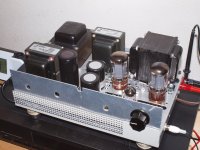
I am posting another of my amplifier designs/builds.
I just wanted to document it . . .
Because I am converting it to an LTP phase inverter, to drive the 6L6GC push pull output (I need to get a matched pair of JJ 6L6GC, add an LM334, and change the input tube from a JJ ECC82 to a JJ dual triode with higher gain (higher u). And I will remove the CCS (Choke), and replace with a self bias resistor for the output tubes.
I hope you like the self-inverting idea, I did one before using a 6C45pi driver, and 6CK4 triode output tubes. The CCS for the 6CK4s was a Choke (but that is another story, and perhaps another thread).
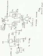
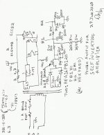
I will attach a picture of the 6L6xx self-inverting amplifier, the amplifier circuit, the power supply circuit, and the performance measurements chart.
Please keep in mind, this amplifier is for near field listening, or for efficient loudspeakers.
Happy Reading!
Questions?
Attachments
The essence of tube amplification IMO, elegant in its simplicity!
The 6L6s are triode wired. Is UL a possibility for this topology?
Since it saves a tube, self inverting should be more common if it was equal to using a phase splitter. What is the limitation of this approach?
The 6L6s are triode wired. Is UL a possibility for this topology?
Since it saves a tube, self inverting should be more common if it was equal to using a phase splitter. What is the limitation of this approach?
Thanks @6A3sUMMER !
I have one question: why do you take the signal from driver anode instead of on top of CCS sense resistor?
I have one question: why do you take the signal from driver anode instead of on top of CCS sense resistor?
A mosfet in a concertina circuit would save you a tube as well, and probably be more linear.The essence of tube amplification IMO, elegant in its simplicity!
The 6L6s are triode wired. Is UL a possibility for this topology?
Since it saves a tube, self inverting should be more common if it was equal to using a phase splitter. What is the limitation of this approach?
The self inverting output stage has been circulating in the experimental realm since before WW2.
And covered Ad Absurdum by many including Yours Truly on these pages a few years ago,
Here is one from WW2 built when parts were hard to find, This version needs an isolation transformer in today's World.
A few commercially sold products have utilized the self inverting circuit.
For those who have a copy of RDH4 you can find references there as well. 👍
Attachments
Certainly that's true of the Poddwatt I built a couple of years back. My sweetest sounding amp.Was that not the essence of the Oddwatt amps?
I tried several versions of the self inverting circuit, most of the measurements & observations are posted here on DIY.
For the test mule I used an old chassis that had run many experimental circuits. In this case the driver is a triode connected 6AU6.
The rectifier is a 5V4 or something similar into a simple CLC HV filter. B+ is ~300V.
The PP outputs are 6V6s. The OPT a Hammond 125E. The main variable for the tests was the cathode tail.
I tried tails of Rs, NPNs, 3-term device & a Hammond choke, The Hammond choke gave the best results.
The spectrums were obtained using a Pico Technology 3224. The THD by an HP 334A.
The output terminals of the HP 334A provides the distortion components for direct viewing & measurement.
That is the RED Trace in the Pico Tech Display.👍
Attachments
-
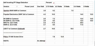 Self Inverting Amplifier Performance Summary.jpg87.7 KB · Views: 114
 -
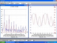 Self Inverting PP 6V6s 3.75 Watts Choke Tail.JPG128.5 KB · Views: 112
 -
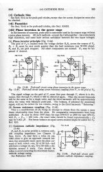 RDH4 p 585 30C Self Inverting Push Pull.jpg413 KB · Views: 129
 -
 IMG_2081 Self Inverting Amp 14H E.jpg281.6 KB · Views: 123
 -
 12AU7 PP Self Inverting OP Firefly.gif25.7 KB · Views: 143
 -
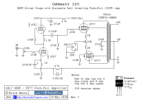 6SL7-SRPP-KT77-Push-Pull-Tube-Amp-CCS.png10.6 KB · Views: 228
 -
 Sparton 8549 Output Stage 7H.jpg66.3 KB · Views: 144
 -
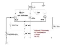 Simplified Self Inverting 6V6 PP Amplifier.JPG22.3 KB · Views: 149
Thread Readers,
Thanks for the questions, observations, and additional information.
My responses:
Since it saves a tube, self inverting should be more common if it was equal to using a phase splitter. What is the limitation of this approach?
Answer: Whether the CCS is in an LTP phase splitter, or in a self inverting output stage, the cathodes swing about 1/2 of the grid signal (it lowers the stage gain). Input stages have low to medium bias voltage; output stages have medium to high bias voltage; which requires more signal swing, Right?
Saving a tube? . . . All my LTP input stages of non-self-inverting amplifiers use dual triodes, so that is only 1 tube.
I have one question: why do you take the signal from driver anode instead of on top of CCS sense resistor?
Answer: Because I have experienced unstable IXYS parts in some circuits.
A mosfet in a concertina circuit would save you a tube as well, and probably be more linear.
Answer: 1. A MOSFET changes capacitance according to the voltage swing. A MOSFET can be sensitive to static, and voltage transients.
2. A tube generally does not have those potential problems (pun intended too).
Was that not the essence of the Oddwatt amps?
Answer: Yes, but an LM317 or other solid stage CCS, is far different than a Choke CCS.
Only 2,3W ?
Answer: My intent is for simplicity of circuitry, low temperature tubes, finesse of 'sound'. I do near field listening, and small living room listening with medium efficiency loudspeakers that have friendly impedance across the frequency range.
If you need lots of power, consider two things:
Other's circuits; and the troubles they experience.
I tried tails of Rs, NPNs, 3-term device & a Hammond choke, The Hammond choke gave the best results.
Thanks jhstewart9 for that comment!
I hope I have answered your questions and comments.
Happy designing, building, and listening to all!
A mosfet in a concertina circuit would save you a tube as well, and probably be more linear.
Answer: 1. A MOSFET changes capacitance according to the voltage swing. A MOSFET can be sensitive to static, and voltage transients.
2. A tube generally does not have those potential problems (pun intended too).
Not sure about that. I thought a mosfet changes capacitance with changing Vds, which as I understand it, remains constant in a split load circuit like a concertina. The static is only an issue when handling, once in circuit they last for ever, and require no heater to operate! The transients are also a non-issue if you pick a device with built in fly-back zeners, or add one externally for protection. Making a mountain out of a mole hill there 6A. If you don't like Mosfets, that's fine. But all devices and circuits require compromises one way or the other. I'd take a mosfet concertina over a self-split design any day, but YMMV, as they say.
There were no MosFETs when this circuit was first devised. And few double triodes to act as ordinary phase splitters.A mosfet in a concertina circuit would save you a tube as well, and probably be more linear.
As a marketing tool the circuit has the advantage of allowing the manufacturer to claim PP, a big deal in the 30s & 40s.
All without the expense of another socket & toob. Things are not always as they seem at first glance! 😀
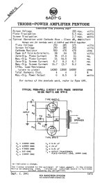
There are other ways, for example the 6AD7G. It was used as a low budget phase inverter driving its pentode in PP with a 6F6,👍
Attachments
Last edited:
not mentioned so far:What is the limitation of this approach?
- strictly limited to class A operation (as soon as the driven output enters class B, i.e. is cut off, the other output does not get any more signal to work with)
- incomplete cancellation of even harmonics (PP with more like a SE distortion spectrum)
constant ...?Vds, which as I understand it, remains constant in a split load circuit like a concertina....
drain goes up while source drops and vice versa ... both with unity gain,
so vds change is twice the input signal swing ...
Sorento,
You were correct about Class A operation only, no Class AB allowed because of the CCS (Constant Current Sink).
. . . But is that an advantage, or is it a disadvantage?
That depends on what you want to get, and what you are willing to trade off . . .
needing to use global negative feedback or not; output power lower or higher; distortion lower or higher; average power supply works OK, or a much stiffer power supply is paramount; simple circuit or complex circuit; etc.
Tradeoffs
You said:
"- incomplete cancellation of even harmonics (PP with more like a SE distortion spectrum)" . . . Well, consider this:
A typical single ended amplifier has dominant 2nd harmonic distortion; and the 3rd harmonic is typically 15 dB less than the 2nd harmonic.
Example: -40dBc 2nd harmonic distortion, and -55dBc 3rd harmonic distortion.
But my self inverting amplifier (this thread) has almost equal 2nd HD and 3rd HD.
1 Watt, 1kHz:
2nd Harmonic - 55 dBc 0.18%, 3rd Harmonic - 54 dBc, 0.2%, THD 0.27%
Everything is what it seems to be, until you find out it is different.
Last edited:
The big issue is that one tube is grid driven and the other cathode driven ... so transconductance is different . the push-pull is unbalanced . I don't see any advantage , just one triode phase splitter economy which is not a good trade-off in my opinion .
Last edited:
But others did see the advantage of claiming push-pull in their product for sales reasons.I don't see any advantage , just one triode phase splitter economy which is not a good trade-off in my opinion .
And made some money with it, unlike some here would do, Success in business often doesn't
care much for what the odd person thinks, as long as the majority think its OK,👍
Try giving your opinion to OddWatt, ask if they care.😀
Of course you are correct. So on an LND150, according to the spec sheet (0-40V signal), the Ciss is constant, at about 8pF, Crss is virtually constant in that order of .5-1pF and, the wildcard, Coss swings from 2-10pF. I hope this isn't the reason anyone isn't using Mosfets where appropriate.constant ...?
drain goes up while source drops and vice versa ... both with unity gain,
so vds change is twice the input signal swing ...
There were no MosFETs when this circuit was first devised. And few double triodes to act as ordinary phase splitters.
As a marketing tool the circuit has the advantage of allowing the manufacturer to claim PP, a big deal in the 30s & 40s.
All without the expense of another socket & toob. Things are not always as they seem at first glance! 😀
There are other ways, for example the 6AD7G. It was used as a low budget phase inverter driving its pentode in PP with a 6F6,👍
Fair point, but last time I checked its 2023 and Mosfets are abundant, cheap, and last forever. I see little reason to restrict one's design to self split when a concertina can be incorporated for less than $1. Just something to ponder. If that's objectionable for whatever reasons, I believe a cheap interstage transformer, albeit more expensive ($6), could also provide the phase inversion. This of course would also save a tube.
Depanatoru,
That is a pretty good catch on your part.
However, let's find out how it really works out . . .
A strange way to look at things, but push tubes are unbalanced versus pull tubes as the signal drives them in opposite phase.
A triode wired 6L6GWB beam power tube has a transconductance of about 4,700 uMhos.
Transconductance:
When the control grid voltage to cathode changes by one Volt, the plate current changes by 4.7mA (and the screen current changes slightly too).
The hidden factor, alluded to in in your comment is the fact that now the plate Voltage and screen Voltage are changing . . .
Which means the transconductance is also changing slightly, true.
But one plate and screen voltage is reducing, causing lower transconductance in that tube; and lower current;
While the other tube's plate and screen voltage is increasing, causing higher transconductance, and higher current.
I think that sounds like push pull, and the resulting 2nd order cancellation.
If that set of conditions does not prove it . . .
Then I think -54dBc 2nd Harmonic Distortion is proof enough.
Right?
Many designers of push pull do not notice the factor that is essentially plate to plate negative feedback.
That and cathode feedback are as local of a negative feedback as you can get (other than plate to grid negative feedback).
The big disadvantage of Class A self inverting output stages, and Class A LTP phase inverters is:
The CCS (Constant Current SINK) in the cathodes reduces the gain of the stage, and they are Only Class A (no Class AB allowed, unless you like listening to severe clipping).
I hope I covered it very well this time.
Happy designing, building, and listening!
Last edited:
Smile & give yourself a break, this is someones experiment into a circuit of the past.Fair point, but last time I checked its 2023
We know there are better ways but that is not the objective of this thread, If you like we could smash all the toobz & go SS. 😱
- Home
- Amplifiers
- Tubes / Valves
- A low power 6L6WGB/6L6GC self-inverting push pull amplifier
