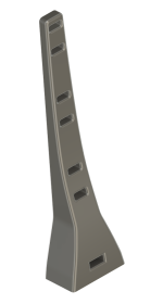
Wire Post for Wire Mangement [3D Print]

UPDATED on June 7, 2024 with "Rev C" design.

NOTE: The improved design, now "Rev C version" attached as a zip file here is designed to be used with an M3 bolt (10-12mm) and associated nut (5.2mm wide by 2mm thick). The design now is such that the M3 nut inserts into the slot, then must be "set" into it's pocket by tightening with the bolt first, to pull it into the hex nut slot. Then the bolt can be removed and the post used as intended. There are 4 different lengths you can print, which are attached below in the zip file (57mm, 100mm, 130mm, & 160mm). Specifically, the change in design from Rev B to now Rev C is the nut is required, whereas previously, you could "thread" into the plastic without a nut. Now the hole is larger than the bolt (or just about same size) and requires the nut to be set into it's pocket first. This is a more secure method and avoids the chance of the nut spinning by creating a pocket perfectly sized for the nut to set into. Reach out to me with any questions.
Pocket View.png


I'm giving these iterations away for free as a thank you to the diyaudio community. Interested parties who need me to print parts for you just send me a prepaid shipping label so no money needs to be transferred. Reach out via PM to coordinate. Cheapest option is print yourself or use a buddy who has a hobby 3D printer.

I created the wire post to help with wire separation and management in my F5m chassis (but works on all amps), and plan to share a final product as I go through iterations to optimize the design. There are now 4 different versions that are based on height (57mm, 100mm, 130mm, and 160mm). They all work well and create great zip tie points to hold wiring firmly in place and appropriately spaced (that part is up to you).

These mount to the bottom plate with a M3 bolt and nut (nut is technically optional). It will thread securely into the PLA print as the pocket/hole is 19mm deep and smaller than the thread outer diameter, however, there's also a slot if you want to add additional "rock solid" connection using an M3 nut (just slide the nut down the slot prior to bolting the post to the plate so the bolt threads into the nut).

The whole point is to create a structural point to connect to that guides and separates the various wire runs (filter board to amp board, amp board to speaker out, etc...). The goal is to make numerous versions for a variety of applications you can print at home (or use a buddies 3D printer, maker space, or fab house). The inspiration is from aerospace industry wire posts used to control and separate wire runs.

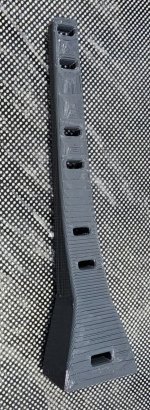
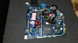
Although the material is "PLA" (Polyacitic acid), it's thermal properties seem to sill hold up inside the class A amps. I have not seen any deformation due to heat, even when the post is very close to the hot heat sink (heat sink is 60°C and PLA softens around 100°C) so as long as the loads are low (aka, just holding wires in place), the post does not deform under the heat loads.

I printed a bunch of these to give away to interested parties. Reach out via PM if you're interested.
Wire Posts Compared.png


M3 Nut just slides into the slot before bolting on.
20240317_015747.jpg


20240317_020024.jpg


20240319_004304.jpg

Attachments

  • 1710666781389.png
    1710666781389.png
    34.9 KB · Views: 125
  • 20240317_015511.jpg
    20240317_015511.jpg
    386.5 KB · Views: 111
  • Wire_Posts_RevC.zip
    Wire_Posts_RevC.zip
    1.1 MB · Views: 51

Active Xover with USB DAC or "sound card"?

Not many options for USB devices that can be used as a DSP/Xover for running 2 way active speakers? After lots of looking I've only found minidsp 2x4hd, sound blaster X3 and X4, and Asus Zonar U7.

So few options exist? There's like hundreds of single channel/headphone output USB DAC's.... but none have the ability to be used as active crossovers due to having only one output.
What are people using? I bought a used X3 and played some music (before trying it with apps to control 2 channels for the xover) and it doesn't sound clean enough to me to consider using it. I'm assuming the X4 is worse, as it's specs are worse. Then the minidsp 2x4hd has a rather poor review on audiosciencereview, and some people say the top end is missing some clarity. I'm coming from a pretty decent DAC I guess, or the X3 is this bad? So I'm worried the minidsp will sound worse too.. will it?

Any other decent performing mulitchannel output DAC I can buy without selling a kidney? It seems to be slim pickings. Also I prefer line-level output, or RCA.

VFET2 Amplifier Kit - all of the good parts!

SOLD!!

For Sale is one Sony VFet2 amplifier kit. You'll get ALL of the interesting/good/hard to find parts in closely matched pairs/quads. You just need to add the generic bits, a power supply, and a chassis to enjoy this beautiful and awesome amplifier.

This kit includes the following:

One pair of original DIYAudio VFet heatsink mounting brackets with predilled holes appropriately spaced for TO-3 cans
One pair of original DIYAudio VFet2 boards
Two complimentary pairs of original Sony Vfets: 2SJ28s measure 7.5v and 7.6v, 2SK82s measure 7.8v and 7.9v
One matched quad of original Toshiba jFets: 2SK170 measure 9.9mA and 9.8mA, 2SJ74 measure 9.9mA and 9.7mA
One matched quad of original Toshiba Fets: 2SK2013 measure 2.27v and 2SJ313 measure 2.27v
One pair ZTX450 transistors (unmatched)
One pair ZTX550 transistors (unmatched)
One pair of IRFP240 transistors (unmatched, but from same die)
One pair of IRFP9240 transistors, matched at 4.16v
Mica insulators for VFet TO-3 cans

Original Toshiba Front End Transistors:
2SK170/2SJ74 jFets were sourced from Spencer at FetAudio years ago. These are known/verfied original Toshiba jFets and a well-matched quad. 2SK2013/2SJ313 Fets were sourced from DIYA member NicMac long ago. They are known/verified original Toshiba parts and a well-matched quad.

Original Sony VFets sourced from Acronman at CircuitDIY years ago. These are known/verified original parts and a closely matched quad.

Here's a photo of everything that is included (oops, the ZTX450 transistors are not in the image, but still included):

VFet2 Kit.JPG


Price: $475 via PayPal "Friends & Family" delivered to your door in the continental US.

Technics SA-303: R703 thermal management

Hi folks,

I found a working Technics SA-303 and want to replace the stock R703 (470ohms - 5 Watts) due to heat damage on the board (circled in red). I don’t think there are any faults. I’ve measured 40 volts across the resistor. That is 3.5 Watts for a 5 Watt rated resistor! I found a thick film 10 Watt TO-220 package resistor and a heatsink that will fit in the volume (30mm x 30mm x 30mm). Wondering if there is a more common replacement for these power resistors. All of the other 10 watt rated resistors are too big. Thanks. Schematic and photo attached.
IMG_3550.jpeg

Attachments

Transformer Chassis Seat - vertical mounting of Antek 300/400VA (3D Print Files)

UPDATE NOTE: If you want to use an Antek 400VA transformer with this seat, you do need to use some 10-15mm spacers for the 130mm pipe strap. The slightly larger diameter of the 400VA over the 300VA transformer means there's a gap that exists between the chassis perforated plate and the strap ends. If you don't care what it looks like, then spacers really aren't needed as they don't increase the strength of the "grip". You do need to use longer M4 bolts (M4 10-12mm work for a 300VA, but 20-25mm are needed for 400VA. The spacers just make a cleaner look is all by flattening the tabs (see pics at end of this post and associated ZIP file with the 11mm spacer 3D file). Don't buy 150mm straps and think they'll fix the issue as those are too long. Stick with 130mm and either use spacers, or live with floating tabs (secure as a rock with either option).

I'm posting the 3D print files here for the Transformer Chassis Seat I created for my F5m build. Version 2 is now the most up to date (3-19-2024), which simply allows a "lip up" option to the perforated pate. The title to this thread says "Antek", but this may work for other transformers with similar widths/diameters. Making tweaks for other transformers is not hard, so feel free to reach out via PM to create a new version for other transformers.

For now, please see pictures from my build in the F5m Kit thread here: https://www.diyaudio.com/community/threads/f5m-kit.408290/post-7627904

Below is a zip file which contains both version 1 and version 2 STL & 3MF files for anyone to download and use however they see fit.

  • Version 1 - Original Design, no slot for "lip up" perforated plate orientation. [I don't see any reason to use this since Version 2, does what this does and more. However, maybe being 2mm closer to the bottom is beneficial for a few folks.]
  • Version 2 - 2mm Taller (allows more squish and squeeze) and has a slot to allow for "lip up" orientation of perforated plate if you go that route. Pics below are of version 2 showing the slot.
1710638632304.png
1710638690439.png


Hardware required:
  • 2x qty: M4x10mm bolts with standard nuts to mount the seat to the chassis. [2x bolt and 2x nut]
  • 2x qty: M4x10mm (or 12mm) bolts with lock nut, or lock washers, and fender washers to hold the pipe strap down. [2x bolt, 2x locknut, 2x fender washer]
    • NOTE: If you want to use a 400VA transformer you'll need M4 x 20mm bolts (25mm also works). Spacers are not a requirement, but will certainly make it look more professional. Spacer print is attached below, or use any spacer that is between 10-15mm.
  • 1x qty: 130mm Stainless Steal Pipe Strap with Rubber Cushion (cost is around $2 or $3 for one, but you typically have to buy more than one)
1710638913826.png


Assembly
  • Start by mounting the seat itself and ensure transformer has a little clearance around it.
  • Set the transformer up with the wires off to sides to avoid interfering with sides of seat.
  • Loosely attach one side of the pipe strap with the lock nut.
  • With your three hands (yeah, a third hand would help as its tricky), put the other end of the strap on compressing the transformer into the squishy seat to get the nut to thread.
  • Tighten it all up nice and tight....all done.

More to come as I try out different designs and try to make something that's more "universal" for different applications.

1710639391396.png


20240316_123722.jpg


Here's a 400VA using 20mm M4 bolts without spacers. Still crazy secure, but kinda looks "janky". (not that anyone sees this once case is closed up)
20240402_145508.jpg


Here's what the 400VA transformner looks like using 11mm 3D printed spacers. Just looks better, but no more, or less secure. Purely cosmetic.
20240402_175524.jpg

Attachments

For Sale ACA Mini Stereo Amp

Selling the first ACA Mini I built which used the ACA Mini Essentials kit, parts from Mouser and extra parts I wasn’t using. Upgrades include DynamiCap input film caps, a medical grade switching power supply, a P089ZB clone of a SMPS DC filter and Welwyn RC55 resistors in the signal path. Everything was mounted on a wooden board for expediency. Ugly, but sounds great!

$100obo including shipping to the lower 48.

Also included is a bare ACA Mini PCB and the original instructions left over from building a second ACA Mini using PCBs of my own design mounted on huge heat sinks.

ACA Mini Amp.jpg

Attachments

  • ACA Mini Dynamicaps.jpg
    ACA Mini Dynamicaps.jpg
    105.9 KB · Views: 135

Rotel RX 400A Repair - Transformer problem?

Hello All

I have chanced upon a faulty Rotel RX 400A

The previous owner said when it was switched on, it briefly lit up (the front illumination) and then smoked and shut down.

On examining the amp, the transformer doesn't seem to be producing any secondary AC - only shows 3VAC.
The schematics do not show any clear transformer specs. It does produce various DC voltages using a bunch of resistor divider networks, but the max seems to be 47V (B1 in the diagram). There is also a DC smoothing cap of 50v 6300uF.
There is an odd 6.3v shown on the primary side that goes to the pilot lamps. Not sure what this is ...?

I am attaching a pic of the transformer, and the relevant extract of the power circuit schematic.

The amp specs are 25w into 8ohm per channel.

So... I am looking for some advice on the specs of a replacement transformer. I presume I need 220V : 50-0-50V , and maybe 100VA atleast? The pilot lamps are a confusing element here, but maybe I can build a DC alternative for them, and/or swap to LEDs. Any further info on this 6.3v is helpful.

Or should I junk the whole power section and drive it with a modern power supply to get 47v DC, and let the other voltages stand as they are off the dividers?

Any advice or pointers are much appreciated.

Attachments

  • circuit.jpg
    circuit.jpg
    533 KB · Views: 143
  • transformer.jpg
    transformer.jpg
    516.6 KB · Views: 129

Humming noise Problem on the inputsignal

Hi There, need some help

i own an effect unit from Ensoniq the Dp4. I have problem with the input signals, there is completly distorted a lot of hum and noise.
i did a check after the D/A converting and the effects blocks. on the signal path after the effect which is going to the outputs everyhing is okay because i can generate i sine wave signal in the effect processor and it sounds good.
What are the possibilties of these issue ?

Grounding?
a faulty Tl074?

Tweeter to crossover at 1KHz?

I'm looking for recommendations for tweeters that can cross at 1KHz. Planning on an MTM with dual 8" woofers that shouldn't be taken higher than 1KHz. It will be active, so steep slopes are possible and OK.

High on my consideration list is the ESS HEIL AMT...it's actually the only one on my list at the moment. What else can do this that's not a large compression driver needing a large waveguide?

Thanks in advance.

driver/amp recommendations for dual mono sub

I currently have lowther dx4 in BLH cabinets, which bass is rubbish, my first plan will be to try and EQ some bass using Nelsons EQ board, if this works, great.

If not then i have 3 thoughts:

1. leave the drivers in the BLH cabs and build/add a couple of subs

2. make and transfer the drivers to open baffle and build/add a couple of subs

3. make and transfer drivers to TQWT (or ML voigt)


Would appreciate any thoughts/recommendations

Thanks

Two Hifonics BXI-2610D, one repaired, another component ID PWN

One amp died when Main positive and negative power in crossed, and the other failed with a multimeter attached while connected to speaker terminals while loaded. Of these two are the components I have to replace with bd139 & bd140, IRFP064N, IRF640. The first amp I have replaced with bd139 and bd140, new 47ohm resistors & IRFP064N, and repaired a trace under the coils.
I have the other amp all with the same symptoms, but additionally, the pwm/protection board has some failed components I have been scouring the forum for. I found here the schematic to help Identify resistor values but no ID on the transistor in position Q5. I dont know what Q5 is, a pnp transistor or linear voltage regulator? https://www.diyaudio.com/community/...-type-3-protectionmarkedtype3-01-pdf.1270452/
Im also reading a handful of odd resistor values on the pwm board as well.
9.jpg2.jpg3.jpg4.jpg5.jpg6.jpg
Where I can get a hold of a replacement board? Tracing Q5 to r10A (top), bottom middle leg to pin 1, left leg to C1898, But What does the right leg lead to seeing as it blown the trace? Probing what little left of the trace shows that its connected to pin1(bottom leg & top). What is the transistor of Q5?

Which Preamp for Less Than Great Sounding CDs?

Much of my source material (uncompressed CD track rips; no SACDs or vinyl), are 60s pop, r&b and soundtracks, which were often victims of excessively applied compression. And some tracks during multi-vocal passages and when orchestrations get busy sound “congested”; possibly due to poor miking/baffling (??), other acoustical and/or electronic causes. So, while not outright crappy (??), much of my music was certainly less than pristinely recorded and/or mastered, even though almost all were issued by major labels.

Further complicating matters was that I had originally attempted to wed this superb midwoofers with cone HF and MF drivers. Login to view embedded media
Luckily, I caught that mistake before wasting time and funds. Troy Crowe and I are now deciding among horn drivers to finish this build. The trouble is that no matter which drivers are chosen I might end up not smiling so much while those speakers are playing anything but my tip-top quality CDs. No doubt that’s one reason why so many horn speaker owners prefer SACDs and even less than high quality vinyl over most music released only on CD.

Thus, while I do have some well recorded and well mastered CDs, perhaps the only way to make most of my stuff sound more pleasing is through careful preamp selection-and/or, where possible, tube rolling and “voicing”, as Aikido owner PierreQuiRoule suggested.

To this end, I’ve heard the Aikido described as very neutral sounding. Whether this is true and/or is the same as transparent sounding, while either may be an asset for playing high resolution source material, how would such a preamp feeding my First Watt F4 power amp driving my >94db/m/watt horn speakers present my more sonically troubled CD tracks?

I’m hoping that the Aikido, built with high quality parts and using the right tubes would somehow behave friendlier towards most of my CDs. If yes, please suggest the best caps, even some of more costly Jupiter models. If the values are too big to fit on John Broskie’s updated Noval board, I might elect to ask John and Phil Marchand about the tradeoffs of redesigning the board to accommodate them.

John also mentions here that he suspects tighter bass can be realized with an electrolytic-free power supply. https://tubecad.com/2018/03/og0415.htm

Also important to know is which are the tubes known to create the most lifelike imaging and largest sound stage?

But which are the tubes which may be too revealing for my more crappier sounding CDs?

Alternately, is there another preamp which would be altogether better for my situation, such the Nelson Pass B1 Korg Triode, or others?

For Sale Capehart Field Coil 12" Speakers

FS Pair Nice Capehart Jensen C12R Field Coil Speakers $400 shipped
These are in excellent condition as removed from a working high end radio. Nice matching readings VC 8 ohm, FC 680 ohm. These have quite the following. Only $350 with free CONUS

Attachments

  • 51A35F2E-81FB-4C1C-8BF9-CFE51CDAF945.jpeg
    51A35F2E-81FB-4C1C-8BF9-CFE51CDAF945.jpeg
    504.3 KB · Views: 57
  • 0AB2C66C-8E2E-48CF-8F2B-E2E662F6F758.jpeg
    0AB2C66C-8E2E-48CF-8F2B-E2E662F6F758.jpeg
    487.6 KB · Views: 69
  • E346093C-65F5-4F5C-8E2F-0A78BD042164.jpeg
    E346093C-65F5-4F5C-8E2F-0A78BD042164.jpeg
    56.2 KB · Views: 65

$325 Lab 12 based PA tapped horn ~ 35Hz extension

There aren't many 12" tapped horns for prosound. The Lab 12 is a great driver for the price, has a strong cone for tapped horn high(ish) compression ratios, and a good amount of Xmax.
12" tapped horns can be much skinnier than 15" and 18" horns, and with the price of the Lab 12 ($165) one can use 4-8 horns and not hurt the wallet too much.
With multiple horns as opposed to one or two large 18" horns, you have more options for stacking and setup.

Figure with the 400w rms rating of the driver, huge amps aren't needed to drive the cabinets to full output.

So here is the breakdown:
$165 Eminence Lab 12 (readily available, been around forever, now two voice coil options available)
$60 per 5x5' 3/4" Baltic birch (2 sheets required)
$40 for Casters, Durtatex, terminal, screws etc

Simple folding, easy to construct. Will have handles and casters for easy transport.
38" High x 30" Deep x 15" Wide cabinet (about 10 cubic feet or 300L)
Low corner of about 35hz
15" wide cabinet maintains truck packing dimms
Group of 4 plus 2000watt amp will provide plenty of output for as little as $1600 ($1300 for 4 cabinets plus $300 for amp)
This build is with the original 6ohm driver. The new Lab12c may also work, not sure.

Lets call it "PAL12 Subwoofer" For P.A. Lab 12 Tapped Horn

DIRECTORY FOR THIS THREAD
AutoCAD drawings, 2D: (post #123)
$325 Lab 12 based PA tapped horn. ~35hz extension - Page 13 - diyAudio

3-D rendering: (post #127)
$325 Lab 12 based PA tapped horn. ~35hz extension - Page 13 - diyAudio

Construction Technique, order of panel installation: (post #129)
$325 Lab 12 based PA tapped horn. ~35hz extension - Page 13 - diyAudio

Initial measured results: (post #82)
$325 Lab 12 based PA tapped horn. ~35hz extension - Page 9 - diyAudio

Now that the sub is constructed and tested, we can post some final specs.
Operating frequency: 34Hz----120Hz +/-3db
Dimensions: 30"x38"x15"
Impedance: 4 ohms
Power handling: 400w rms, 800w program High pass 32Hz 24db/octave minimum
Weight: TBD

Woofers & tweeters by Visaton

Hi,

I am selling surplus drivers left from various projects in the past that I do no longer need :

1) Woofers W-300. Almost like new. Asking 50 euros per piece, I have 4 units in total.
2) Mid bass units AL-170. Good condition. 70 euros for piece, 2 units total.
3) Tweeters KE25SC, highly valued. 85 for piece, 2 units total.

I sell only in pairs, shipping from EU. All speakers come with original boxes and are fully working. Used very little, mostly stored for several years.

Attachments

  • IMG_0350.jpg
    IMG_0350.jpg
    404.8 KB · Views: 69
  • IMG_0353.jpg
    IMG_0353.jpg
    339.1 KB · Views: 62
  • IMG_0355.jpg
    IMG_0355.jpg
    357.9 KB · Views: 59
  • IMG_0357.jpg
    IMG_0357.jpg
    411.9 KB · Views: 57
  • IMG_0396.jpg
    IMG_0396.jpg
    394.2 KB · Views: 58
  • IMG_0397.jpg
    IMG_0397.jpg
    382.4 KB · Views: 60

Modular phono preamp

I've just finished the build for the first pcb of my modular phono preamp project.

It does RIAA compensation and basic amplification suitable for an MM input.

I intend to design an MC stage pcb, an input connector pcb, an output connector and power pcb (perhaps with battery option), a rumble filter pcb. They will slot together with dupont-style edge connectors, allowing various configurations.

The two channels are independent in this pcb, roughly mirror-image, allowing a star-ground to be used at the power supply end.


modular_riaa_preamp.jpg


SMT is used where possible to keep size down. PPS capacitors seem to be the best compromise for low distortion and SMT availability - here a single value, 10nF, is needed.

The RIAA circuit topology is slightly unusual in that each of the poles and zeroes is an explicit separate RC pair. Care has to be taken to keep the opamps stable into capacitive loads in this topology (the 33pF capacitors and 470 ohm resistors).

The nominal component values give exactly 75µs, 318µs and 3180µs time-constants. Alas I could only source 2% PPS capacitors, but 0.1% thin-film resistors are used throughout.


Where DC-blocking is needed I used back-to-back electrolytics of high value with a centre bias to keep them formed over time. The 22M resistors were a guess for this purpose - the time constant is measured in hours so in theory won't have any impact audibly.


modular_riaa_preamp.png


There is no input DC-blocking capacitor, as my calculations show the tiny bias currents of opamps are not going to have any effect on a MM pickup (despite what a lot of people glibly state). 500nA in a 1k5 winding gives an offset of a fraction of a mV, and a few mA-turns of magneto motive force, insignificant compared to signal levels, especially when the inefficiency of the MM cartridge as a motor is considered. I think I'd need to see some hard evidence to the contrary, such as a plot of THD v. offset current.

Yamaha P2200 replacement amp boards

Hello DIY'ers.
I have been given a Yamaha P2200 that is completely broken and not worth repairing - particulary so as the whole left channel has been removed. The best path forward is to try and reuse the chassis and toroid etc to build a whole new amp.
The power supply consists of a couple of 100v 22,000uf cans and I'll be replacing that fully. No problem there.
The rail voltages are very high though @ +/- 80VDC and I'm wondering whether anyone has some recommendations on suitable amp modules for this. I did read a very old thread in here about repowering a P2200 with Aussie Amplifier modules and while this is an option, it's a very expensive one.
So, does anyone have some thoughts on what I can possibly use or consider?
Cheers

FR-64s endpoints of the horizontal movement

Hi everybody,
I have two Fidelity Research FR-64s tonearms. They both work perfectly.
I noticed, however, that they have the different endpoints of the horizontal moving.

One of the arms can be placed directly above the TT spindle, just this position is the endpoint of its horizontally
movement.

My other FR-64s can be horizontally moved through the above mentioned endpoint a little bit further (apr. 20 degrees after the reaching the TT spindle).

The same situation by the moving right: the first arm can be horizontally moved just to the rest area, my other Fr-64s can be moved outward after the reaching the rest area a little bit further.
Is with this FR-64s something wrong and the arm must be repaired or serviced?
Thank you for any advice.

Paul

Automatic volume leveler

I've got the following circuit which keeps the level of an audio signal fairly constant.

Due to adding a VU meter circuit and only having a dual OP-AMP to drive the meter, I have an extra OP-AMP section.

Is it possible to connect the inputs to the + and - inputs of the OP-AMP and use it to drive a meter to indicate how much the circuit is operating on the signal?

FB_IMG_1710602130814.jpg

LX Mini 3D Print

After my fateful post re:LX Mini plan pricing, I did order the kit and plans from Madisound. Par for my course anyway, I decided to improve the WAF. Others have done 3D printing but I suspect they narrowed the focus a bit. These prints took a while and are (hopefully) cosmetic only. At least I’ve tried to make that way….

C786BB0A-A84D-443D-AF81-F72564DF1745.jpeg


It’s not finished as I plan to incorporate a white wooden base (next time I would use a different filament color). And just to further my appreciation of “measure twice, cut (print) once” I managed to use the 6” flange OD as the bolt circle instead of the actual bolt circle. Damnit.

Z

For Sale Iron Pre Single Ended Essentials KIT

SOLD!!

I've decided to sell my unassembled Iron Pre Single Ended kit. You get everything that came with the kit from the DIY Audio store. I could post an image, or you could just look at the link to kit in the DIYA store. You get:
  • 1x Iron Pre SE PCB, good for two channels
  • 1x Iron Pre “Twister Board” PCB for Input Selection with LED indicator and Mute x 1 positions (LEDs not included)
  • Active Devices (QTY based on SE board)
    • 2x 2SK370 Matched JFET Pairs (J1, J3)
    • 2x 2SJ74 (J2, J4)
    • 1x BD139 (Q1 )
    • 1x BD140 (Q2)
    • 7x BC546 (T1, T3, T5, T7, T9, T11, T13)
    • 7x BC556 (T2, T4, T6, T8, T10, T12, T14)
    • 2X LM336 2.5 (U1, U2)
    • 1X IRF510 (M1)
    • 2X IRF9510 (M2, M3)
  • 2X CineMag CMOQ-4HPC (high nickel laminations) Signal Transformers
Everything is completely new and unused/never soldered. I opened the static-safe just once in order to verify the contents to make this list. Your price is exactly what I paid for it from the DIYAudio store: $150 + $15 for paypal fees and shipping. Shipping to the continental US only. First response gets it.

If this is still available in the morning, I'll post a few images (exactly the same as what you see on the store link).

Tube Lab SPP build

Been a long time since I have posted in here. Starting a Tube Lab SPP build and have ran into an issue with a bit of a solder bridge and was wondering if this will be an issue?

R204/R203 and pin 8 on the V200 tube socket? I've been trying to clean it up🥴
17105933222312925920875283613752.jpg


Looks like R204/R203 are connected? But definitely get the solder away from pin 8. Just want to make sure before I overdue it trying to remove something I don't need to.

Thanks in advance

SSL Matrix 2

Please let me know if you have any questions about this board. I have one of these at my studio in Orlando, FL. East Rom Suites It is by far one of the best consoles for a small studio footprint. It is definitely an amazing bridge between analog and digital.

10c93055-8023-4394-9a3a-dd4b542f9955.jpg
76fcd8d2-16a8-4d62-8eca-343d01b6ca26.png


The Standard information:
  • 32 x 16 x 16 'Insert Router' for up to 16 external hardware processing devices
  • Hardware processors can be inserted via console controls or cross-platform drag-and-drop software browser
  • Stereo or 5.1 EXT monitoring outputs with independent Main and Mini monitor control
  • Hardware processors can be inserted individually or as 'chains'40 input Super Analogue summing console
  • Stereo Aux Send and 4 x Mono Sends per channel
  • 4 Stereo Returns with full stereo mix bus routing
  • Dual Stereo Mix Busses with summing Inserts and reassign In Line' DAW monitoring with 'SuperCue' headphone mode
  • Stereo or 5.1 External Monitor inputs
  • Stereo digital I/O (S/PDIF, AES/EBU) with SSL converter technology
  • iJack front panel Monitor input
  • Heavy-duty external PSU16 analog line channels with two inputs per channel
  • Artist Monitor output with independent EQ and monitor source selection
  • Single button push flips control between the analog signal path and DAW software
  • Multi-layer control of up to four DAWs simultaneously
  • Ergonomically advanced hybrid hardware control surface
  • Digital scribble strips for constant visual feedback
  • Fader-linking for analog channels
  • Additional motorized 'Focus' fader for simultaneous DAW/Console control
  • 16 channel strips each with motorized fader and assignable rotary encoder
  • Total Recall for analog console controls
  • General purpose MIDI controller mode
  • A-FADA or MIDI Fader automation
  • Ethernet MIDI connectivity
  • Simple drag and drop insert router page for configuring hardware device chains and loading inserts
  • Intuitive cross-platform remote browser for system configuration and project management
  • Cross-platform 'Logictivity' remote browser interface
  • Programmable hardware buttons for sending standard USB keyboard commands

The "Dutch" Karlson 12

- has been a popular build in Europe and spoken of, like Karlson boxes in general, as playing very loud with very little visible cone movement.

I would assume its based upon Karlson's 2nd K12 with a distributed slot port which appeared around 1956 and published in the July 1958 issue of Popular Mechanics. Its 3 port slots are much larger than Karlson's K12 with 6 saw blade-width cut slits, so should have less velocity. The panel above the speaker baffle, fully perpendicular.

IIRC, there was a build some years back on Diyaudio, but I've not been able to locate the thread or post.

Article https://i.imgur.com/SBDGevY.png

Plan http://home.planet.nl/~ulfman/images/Plans/new12in.gif

Karlson's 2nd K12
6553ba203ae53f80f8cb08e62dda952a--speaker-plans-hifi-speakers.jpg


a couple of Karlson's mid 1960's K12 - one apparently offered with a blank port panel

(the first pair are mine)
PvBejSd.jpg

ZxGbIup.jpg

6PBeU6n.jpg


A down-scaled version of the "Dutch" Karlson 12
7cd715fb96541892e2aa2b06e624674d--transparent-speakers.jpg

Alternatives to The Beaglebone

I don't think there are many of us left using the Beaglebone/Hermes/Cronus. It seems development for the Botic driver has been dropped. I have been using GentooPlayer but the developer no longer supports the BB. He said it's not worth his time. This is really too bad because the BB is much superior to the RPi for our purposes. One alternative is supplied by IanCanada. He has a lot of products and it takes some time to sort them out. Just thought I'd post my experiences with this in case anyone is interested.

I use HQPlayer on a separate PC to convert everything to DSD256 and send over the network to the BBB.

I purchased a FiFoPi from IanCanada along with his PurePi power supply. I connected the BuffaloPro to the FifoPi using I2s. Just to get started I loaded RoPieee on a RPi4. Had to choose "Generic I2s DAC" nothing else worked. The best I could get was DSD64 using DOP. This is apparently a limitation of Linux on the RPi. The BBB does not have this limitation even though it uses Linux as well.

Initially I felt the sound was improved and more detailed but a little forward in the upper midrange. Bass was very good. I'm told that the clocks need time to burn in so I listened to this setup for a week or so. Ultimately it became a bit fatiguing. I could maybe make some adjustments in my speaker crossovers to help. For now I have gone back to the BBB/Cronus but substituting the clocks from IanCanada. This is a happy medium with bit more detail but not quite so searing.

3-Way design with Dayton RS52AN

I am planning a small size 3 way with Dayton RS52AN which I have, Initially brought with an Idea to build Black Box (Dayton RS270S-8 + Dayton RS52AN-8 + Dayton RS28A-4) --https://www.humblehomemadehifi.com/download/Humble%20Homemade%20Hifi_Black%20Box.pdf but later to my delay RS28A-4 has become obsolete.

Due to space constraints Iam not opting for http://zaphaudio.com/ZDT3.5.html

As I require a small footprint 3-way speaker, My thought is to go with a passive radiator for the woofer.

Has anybody tried building a 3-way Dayton RS52AN ( other than the above builds )?

Kindly help me to complete my build, your inputs are highly appreciated.

3" FR speakers for micro stereo upgrade

I get second hand all in one box micro stereo with 3" speakers and sound of it really needs upgrade.

I made measurements in room from 1m and there are problems to solve. Room modes have very little influence and holes on 500 Hz and 1.2kHz are from speaker.
Black line is bass reflex port near filed and blue is speaker near filed measurement.
Port+box have very low Q, probably because air leaks, this can be easily fixed, but can help only increase very little in bass response.

MicroStereMes.png


My first idea was Alpair 5.3.
Speaker box volumes are 1,75 L what is very little but it cannot be increased.
Simulation of Alpair 5 in existing box with existing port ( 30 mm diameter, 80 mm length) give not best results, solid lines on image
Optimized volume configuration lines are doted, 3,58 L box, port 30 mm diameter, 80 mm length.

What other 3" FR speakers can be used with small bass reflex box volume?

Alpair5.PNG


If I increase port length in simulation to 140 mm change is to better but little.
Alpair5increasedport.PNG

STC 4033X info

Hi, I am wondering if anyone has any information on 4033X's parameters?

Previous links with datasheets appear to be removed a long time ago.

On radiomuseum (without sources), it states that it requires 4V filament, but stated the 6V tube, 4033L as "Normally replaceable-slightly different"

I note that online tube sellers commonly label 4033X together with NT37, which was stated to use 6V (http://www.r-type.org/pdfs/cv1220.pdf)

Any ideas if 4V on radiomuseum is a mistake, or could the 4033X be one of those tubes that are usable on both listed voltages?

Technics SU-7200 Replacement power transistors

Good afternoon, I am writing to inquire about something specific. I have a Technics SU-7200 to which the power transistors have been changed, and that ones are now short-circuited. Could someone advise me on whether using the original 2SD526-Y and 2SB596-Y matched transistors would make the amplifier work perfectly, or if there are other transistors that might work better? I'm not an electronics expert, but I have some knowledge. I would be very grateful for your help as a humble radio enthusiast. Thanks in advance.

Ultra-low distortion, non-GFB, discrete, non-complex, DAC line level amplification ... does it exist?

Hi all,

Well, I reckon this is going to be a quite short thread as my feel is that what I am looking for does not exist ... But knowing that there are many knowledgeable people here there might just be someone knowing something about this ...

Is there an ultra-low distortion (<125 dB THD (DC to ~30 kHz), non-GFB, discrete components (non-opamp), non-complex design (basically "not that many components") DAC line level amplification circuitry (gain 5-10x) in existence somewhere accessible? I am asking because MarcelvdG's RTZ FIRDAC design in this post:

https://www.diyaudio.com/community/...t-register-firdac.379406/page-55#post-7419240

shows great potential, however, I would prefer to have the subsequent amplifier be a non-GFB & discrete design (and, yes, there need be filters but "first things first").

Yet I have never seen a non-GFB & discrete design with such low THD values - so my guess is that it doesn't exist ... ? Or may I just have missed it?

Cheers & thanks for reading & maybe replying with good news ;-)

Jesper

Frankenplanar speaker: Acorn ESL / Maggie ribbon tweeter hybrid

Inspired by StigErik’s hybrid Magnepan speaker project (please come back StigE if you are reading this) I’ve decided to put together an unusual hybrid speaker system comprising Maggie ribbon tweeters, ESL mid range (cut out of some old gen 1 Acorn panels) and OB woofer arrays. The ESL mid range will use a 3 micron diaphragm.

On paper it probably doesn’t look very sensible to mix 3 different transducer types but I’m in a position to try it without going to enormous expense and so why not give it a go. To maximise the chances of success I will be using Audiolense for the crossovers etc.

Still in the planning stage but I will post updates as I progress.

The Pioneer Super Linear Circuit

Every now and then, we do something totally different, for fun but also for bench-marking.

This is almost 180° to what we normally do.
No FETs, no NOS parts, no 0.3% matching (although hfe matching does improve performance significantly).
All parts are in active production; you can get them from Digikey or Mouser for very little money.

It is Class A, has no global feedback, can deliver +/-10V into 30R before clipping.
It delivers 1Vrms into 30R at an amazing -97dB THD, and has a -3dB bandwidth of 2MHz.

You can read about it here :
http://xen-audio.com/documents/SLHPA/SLHPA Description Public 171005.pdf


Patrick

.

Attachments

  • 170928 SL HPA Proto 1 Top.JPG
    170928 SL HPA Proto 1 Top.JPG
    298.7 KB · Views: 7,817
  • 170928 SL HPA Proto 1 Btm.JPG
    170928 SL HPA Proto 1 Btm.JPG
    309.4 KB · Views: 7,706

ECC83 + ECL86 guitar amp pondering...

Hey gang, so I have this old valve radio which has an ecc83 preamp tube run as a two channel stereo and then there are ECL86s for each of the channel in the power amp section.

Now, although it somewhat worked while still in the wooden enclosure, something got damaged while i was taking it out. I don't really feel like bothering to measure all the old dusty buggered semiconductors, also the construction of the multiband radio receiver is a big mess.. or maze.. or both so to get to the board where the amplifier section is mounted is extremely inconvenient, that is why i have decided not to try to mend it but rather salvage what i know is good and functional and build a new simpler amp around those parts in a fresh chasis: the transformers, tubes and sockets and the amp board.

Now my question.. is it possible to rewire the two triodes of the ecc83 as two gain stages and then run it to one of the ecl 86's in the power section?

And if so, is it possible to wire a gain pot? The radio obviously only had a volume one, treble, bass (and stereobalance which i would remove bcs i do not intend to use it as a stereo amp).

I do have a full schematic and parts data sheet. But I am seriously considering just using the ecc83, one ecl86 and just point to point wiring it bcs there is a lot going on the original pcb and there are leads and switches all around the place bcs of the multiband radio receiver..

I know I should probably just buy brand new parts for a simplified princeton or whatever 🙂 but at the same time I would like to give new life and purpose to this old junk which has been lying in the attic for decades. And I do want to build from these parts bcs I know it sounded pretty good considering its age and state and the fact those werent even guitar spekers. Login to view embedded media
Here is the maintenance manual with the schematic of the radio at the end http://www.oldradio.cz/schemata/ts538sn.pdf

Offset voltage in Lang 20W class A mosfet amplifier

Hi everyone. Having built 3 Lang 20W class A amplifiers, after finishing the 4th, during the final measurements, the dc offset is 7mV at the right channel and at the left is -25mV. In all the previous amplifiers the offset voltage was between +5 to +13mV. The only difference among them is that instead of +-20V regulated voltage supply, +-28V unregulated power supply which I think it is not a big deal. My worst problem has been in matching the BC560C. i have bought 100 of them and their Hfe was below 600 except of 2. So While all the BC550C were from 600 to 612, I have placed the only 2 BC560C with Hfe 600 at the differential amplifier and the rest where it has been needed to. The quiescent current was set for 2A as per the instructions of the article. I use separate toroid transformers with 2 separate secondaries 2 X 20VAC/8A and 4 X 6 X10.000uF so every negative and positive voltage use 60.000uF each. All the components have been purchased by Mouser except the BC560C. The output waveform are clean and undistorted at 1Khz/4V input from the wave generator. Do you think that those difference will affect the fidelity of the amplifier and if yes how can I fix it? Check the attached files for every helpful detail. Thanks a lot in advance.

Attachments

  • Lang 1.jpg
    Lang 1.jpg
    328.3 KB · Views: 323
  • Lang 2.jpg
    Lang 2.jpg
    407.4 KB · Views: 314
  • Lang 3.jpg
    Lang 3.jpg
    456.4 KB · Views: 277
  • Lang 4.jpg
    Lang 4.jpg
    392 KB · Views: 277
  • Lang 5.jpg
    Lang 5.jpg
    329.6 KB · Views: 501
  • Lang 6.jpg
    Lang 6.jpg
    294.5 KB · Views: 514
  • Lang 7.jpg
    Lang 7.jpg
    368.1 KB · Views: 506

Matching Tweeter, Woofer, and Amp

I hope I posted this in the right place... I was trying to build a portable speaker. My budget varies but I didn't want to go crazy. It started out as a simple idea... build a speaker box that I could plug in my Qudelix 5K to have the awesome app and equalizer. I didn't care if it didn't sound "great"... My goals were: 1: Try not to spend more than necessary. 2: Don't make it TOO big, I wanted the biggest speaker to be no more than 4 inches if I could help it. 3: I wanted to separate the highs and lows between two speakers, A tweeter and a woofer/full range, with a crossover. Added: 4: I realized flat 20hz to 20,000hz was NOT going to happen, so I decided I wanted it to have around 60hz to 19,000hz on a relatively decent flat overall response curve, made more difficult as most Woofers I looked at had a bit too much fall-off around 100 to 80hz. BONUS: 5: Use 4ohm speakers for power efficiency.
I tried to learn what I could browsing many forums and actual build guides.
Looking at Ohms I saw things like: "Make sure the speakers are the same Ohms as the Amp or you will blow the speakers or burn out the amp," or "The speakers can be a higher Ohm than the Amp but they have to be the same as the other speaker," or build guides where the speakers' Ohms didn't match at all.
Looking at Wattage I saw things like: "Match the RMS wattage of all the components," or "Make sure the wattages of the speakers are a bit higher than the Amp so the Amp can't blow them," or "If the speakers' wattages are too high compared to the Amp's then they will stress the Amp."
Looking at Sensitivity I saw: "The ohms and wattage don't matter, it's the sensitivity of the speakers that matters, match that instead," but on some build guides I saw, none of that matched either! I saw things like a 20w RMS 4ohm 90dB 2.83V/1m Tweeter being used with a 50w RMS 8ohm 80dB 2.83V/1m Woofer!
I'm incredibly confused! I spent several days looking at Speakers and Amps trying to just match everything so I don't have to worry about any of it, but that being very difficult isn't even what has stopped me... It's my realization that I'm in way over my head! I'm obviously either missing something or overcomplicating it... I just want to know how to match a Tweeter to a Woofer with DECENT accuracy and not blow anything up...
...
Now with how expensive the parts are that match in ways similar to those above, I'm considering doing a mono Amp with only 1 Tweeter and 1 Woofer for now and eventually building a second later splicing them together by feeding each the split left and right signal... or using two Bluetooth transmitters, each with a split left and right signal out of my Qudellix to each of the Satellite speakers.

8 vs 16 Ohm drivers: different frequency response?

Having examined the data sheets of 18 sound’s comp drivers in recent days, I’m intrigued by the fact that depending on the 8 or 16 ohm version, there are notable differences in the frequency response, with a tendency to more accidents and decrease in the UHF region for the 16 ohm versions.

The impedance curves also tend to exhibit more accidents with several maxima.

Only explanation I came up til now is that the 16 ohm versions involve a greater distance between core and diaphragm (due to longer moving coil??).

Anyone can comment on the above?

M&K MX5000 Amp

Hello, I’m new to this forum but found it while searching for thoughts on repairing an MX5000 amplifier. My issue started out as loud uncontrolled low frequency noise coming from the sub. I thought it might just be too much gain on the sub so I went to turn it down a bit. I got more of this noise when exercising the gain potentiometer so I thought it might be the issue. It showed as an A50K potentiometer so I ordered what I thought was a replacement. Turns out it was a B50K but I figured it was ok so I soldered it in. Well, it didn’t work and I found/ordered an A50K. I took out the B50K and soldered in the A50K and now I’ve got nothing. Occasionally I get some weird noises. I took it apart this evening just to look over everything and I don’t see any evidence of electrical damage on either of the circuit boards. I connected all the wires back up internally and and plugged it back in. Then got some chattering noise with no audio inputs. Hooked up audio inputs and nothing and the chattering has gone away. I do get a low frequency hum if I touch both the positive and negative terminals on the low level audio inputs. Is the amp dead? Is there anything I can easily check? Can I put some sort of steady state resistor in the place of the pot to just check it? I’ve learned that I can get a replacement plate amplifier which will probably solve my problems. However, I just want to make sure I exhaust all my options before doing this.

Thanks for any help that you can provide.

Does a "ported stub" affect a ported chamber?

Here is a fast approximation of a 6th order I'm building,
where the middle baffle and outer walls are set in stone and cannot be moved. But the baffle can be sawed, partly...
1710460669879.png

So to convert this into a properly working 6th order I have to "steal" space from the rear chamber to the front chamber.
But there is a port and a brace in the way, making the opening to the "stub" smaller than the outer/front port.
The stub opening would be 900cm2 and the port would be 1000cm2.
Now the question is, will this stub have it's own resonance or somehow otherwise affect the front chamber loading?

For Sale Dayton Parts Express subwoofers Midrange and tweeters

I am parting out a set of prototype speakers a friend had built for his recording studio. just as he got his studio finished. the landlord sold the building so these have zero use!!!

I have FOUR (4) Dayton Audio RSS265HF-8 10" Reference Series HF Subwoofer 8 Ohm these are currently $205each plus tax and shipping. asking $140 Each or best offer. $250 for a pair shipping not included, or buy all four for $500 and get free shipping in the USA! and these babies are HEAVY!

I have FOUR (4) Dayton Audio RS180-8 7" Reference Woofer. these are currently $70 each plus tax and shipping. asking $50 each, $100 per pair plus shipping or buy all four for $200 and get free shipping in the USA

I have TWO (2) Dayton Audio RST28A-4 1-1/8" Reference Series Aluminum Dome Tweeter 4 Ohm
these are currently $42each. asking $60 per pair plus shipping.

or buy ALL for $750 with free shipping in the USA. may consider offers.

all drivers have zero play time on them. but some woofers have some white paint on the rubber surround. should clean off easily.


20240109_190543.jpg
20240109_190556.jpg
20240109_190601.jpg
20240109_190608.jpg
20240109_190715.jpg
20240109_190717.jpg
20240109_190726.jpg
Located in Minnesota. Please PM me for details
20240109_190539.jpg
20240109_190730.jpg
20240109_190732.jpg
20240109_190736.jpg

Recommendations for a Better Signal Processor (4+ inputs and 8+ outputs?)

I'm looking for a better processor for my unconventional active 4 way speaker project. I am currently using the Peavey 48VSX, which has the main features I'm looking for, but I am finding it is fairly noisy for a home environment. And it would help to have a few more inputs, whether by having a single unit with more inputs, or two units that can be configured together.

The noise I'm experience is signal noise, and also the fan is very loud. I've actually unplugged the fan, since none of the components appear to need active cooling.

My wish list is:

Rack mount--1RU ideally
4-6 Balanced inputs (XLR?)
8 Balanced outputs (XLR?)
Low noise
10+ parametric EQs per channel (Including high pass, low pass, shelf, etc)
Matrix programming, delays, etc
Expandable (I might go multi-channel at some point)

My budget is going to be up to ~$1500. Hopefully less, but I don't expect to get something for nothing.

18" up to 400-500 Hz

I got the idea to build a large, DSP controlled 3 driver 3 way speaker by using a 18" woofer (namely the Faital Pro 18FX600). The midrange driver needs to be used from 400 Hz, otherwise it's distortion is high. My initial problem is the 18" seems to resonate/distort if I run a sine-sweep in free-air mode. My Eminence Kappalite 3012LF doesn't acts like this. But recently read somewhere a similar problem, and when the 18" was secured to a baffle/box, the distortion had gone.

The 18FX600 is a relative low Mms 18" with not too high Le, so I thought it may be usable up to 500 Hz, where it not beams yet, according to the factory off-axis response.

Does anyone have experience with large woofer free-air distortion that gone away when the driver is secured to a box?

I tried the smaller brother 15FX560 which have very good reputation amongst builders and that woofer also sounded distorted in free-air.

Any replies appreciated!

Please explain…

I have posted the following question, in multiple forums, without really getting a clear answer. So, I hope the knowledgeable people here can answer…

what about the design, of a tube amp, makes it sound more syrupy than analytical?

somewhere around the year 2000, tube amps started getting more analytical. They still sound good; however, they became more analytical, clean, solid state sounding (I know they still have the holographic airy sound). I don’t think parts just got better; rather something in the design must have changed to create this change.

personally, I like the old sound better and would like to figure out of to get an amp done, with the old characteristics….

Free stuff from 20 yrs ago

I came across a bunch of stuff. Hopefully of some use to someone (prob not). See pics. Free.

All ask in return is an authentic schematic to the chimpamp LM3886 and LM3875 offerings.


Regards, Vinay
1710532630212.jpeg
1710532651260.jpeg
1710532671277.jpeg
1710532687897.jpeg

Attachments

  • 1710532706675.jpeg
    1710532706675.jpeg
    263.6 KB · Views: 71
  • 1710532723852.jpeg
    1710532723852.jpeg
    263.6 KB · Views: 77
  • 1710532743546.jpeg
    1710532743546.jpeg
    263.6 KB · Views: 68
  • 1710532760340.jpeg
    1710532760340.jpeg
    263.6 KB · Views: 72

Fostex XR 7 need help with bargraph meter

Hello everyone!

I’m seeking advice on how to repair my bar graph meter, which is currently unresponsive. I would greatly appreciate any assistance. I love this stuff and enjoy making things with it.

When I play a cassette, the bar graph meter remains stuck (see PIC_1). However, when I plug in my headphones, the bar graph get stuck to a higher position. When I remove the ribbon (as shown in PIC_2), the bar graph functions normally during cassette playback.

I hope someone can assist me with this issue. Thank you 🙂

Attachments

  • PIC_1.jpeg
    PIC_1.jpeg
    246.2 KB · Views: 63
  • PIC_2.jpeg
    PIC_2.jpeg
    509.1 KB · Views: 68
  • PIC_3.jpeg
    PIC_3.jpeg
    796.1 KB · Views: 74
  • PIC_4.jpeg
    PIC_4.jpeg
    844.6 KB · Views: 75

For Sale [USA-FL] Cleaning out the collection - Drivers, amps etc

I have a variety of used and unused drivers (subs, mids, tweeters, full ranges) that I will be adding to this listing over the coming weeks. Anything listed here has been stored either in the temperate basement of my homes or more recently in a climate controlled storage unit. I am trying to price everything for a quick and easy sale.

Offers welcome, combined orders I'll be way more lenient on pricing.

All prices are without shipping, and I will charge actual cost via pirateship. Combined shipping encouraged! I can ship in or out of the USA, but for my own protection shipping outside the US is non-refundable, no returns. Within the US you may return items at your own expense for a full refund (ex-shipping) within 14 days of receipt. Local is St Pete, Florida. Meetups welcome within a reasonable distance. I accept Paypal G&S, or local cash.
For Paypal, please send your paypal to me in a PM and I will invoice you through Paypal's G&S so we both have protection for the transaction.

To start:

$160 for all 8
8x SB13PFC25-08 (one case).
https://www.madisoundspeakerstore.c...b-acoustics-sb13pfc25-08-5-paper-cone-woofer/
Each has been measured, one mounted for test. Unused otherwise. (must buy all)
Login to view embedded media
$75
for 6
$120 for 12.
12 8" woofers from ApexJr circa 2012. I think these were a peerless or clone. I tested each one and mounted at least one for measurements but never used them.
Shipping is 2 boxes at 40lbs each.
Login to view embedded media
$60 for 60 drivers.
60x Aurasound AS3-75-16FR 3" drivers from madisound 2012. Some tested, most never removed from the box. Must buy the lot.
Login to view embedded media
$75 for the lot.
156 mylar tweeters from apexjr. I must have misplaced the 4 I tested, I originally bought 160. I never took the time to build that line array...
Login to view embedded media
SOLD $40 each, 2x Dayton titanic MKIII 12" in near mint condition. I bought these around 2011-2012. Used them for a couple years in a HT sub pair, then replaced them with something bigger but kept them in storage expecting to do something with them.
Login to view embedded media
$20
1x NS270-44 10" low profile subwoofer. I only ever tested this, never used it.
https://imgur.com/a/oTBl8Xi

Question about bluetooth with some Vonyx Speakers.

Hello, I have two vonyx VSA12BT which both have bluetooth. I don't have a mixer or console and want to conneect them together via bluetooth. Is that possible? To pair them both with one device like a phone or a pc ( with bluetooth features of course ) or a laptop but both of the speakers playing the same sound because I couldn't do that as I could only be able to pair one of them. Please help me.

The Gedlee Metric Demystified

Since the 1930's, measurement of Total Harmonic Distortion (THD) has been recognised as a poor arbiter of sound quality. The Gedlee Metric, Gm, attempts to overcome the shortcomings of traditional THD measurements, and to quantify non-linearity in a way that corresponds much more closely to the psycho-acoustical perception of distortion. It is derived from the Transfer Function T(x) of the DUT. Since, in principal, any signal can be used as an input to determine the Transfer Function, Gm can be said to be a characteristic of the DUT rather than a characteristic of the output signal. Characteristics of the human hearing system such as masking have also been allowed for in the formula for Gm. Experimental results indicate that for low to intermediate levels of non-linear distortion, the Gedlee Metric has a much improved correlation to the subjective perception of distortion, and is a significant predictor of subjective sound quality, when compared to traditional metrics such as THD and IMD.

The original AES papers describing the Gedlee Metric are available on Earl Geddes's website:

Lee and Geddes: Auditory Perception of Nonlinear Distortion, AES October 2003. Part I: http://www.gedlee.com/Papers/Distortion_AES_I.pdf
Part II: http://www.gedlee.com/Papers/Distortion_AES_II.pdf

An undoubted obstacle to the adoption of Gm is that the mathematics involved in calculating Gm are complicated compared to the simplicity of THD calculations. It is also likely that many manufacturers are comfortable with consumers' misguided belief that low THD is a meaningful predictor of sound quality, and design and market their products accordingly.

The calculation of Gm involves two steps: 1) the derivation of a function T(x) which represents the normalised transfer function of an audio black box and which is amenable to differentiation; b) plugging T(x) into the equation for the Gedlee Metric Gm proposed by Geddes and Lee in their AES papers.

Published suggested methods for deriving T(x) have to date utilised either the theory of non-linear systems or trigonometric identities to derive a polynomial expression of T(x). I found both approaches very complicated, so I developed a hassle-free method of calculating Gm, and have created a spreadsheet to facilitate this. The spreadsheet derives the coefficients of a trigonometric expression of T(x). This set of coefficients can then be plugged into a short worksheet for Sage Math Online which then calculates Gm virtually instantly. The spreadsheet contains directions on how to use it, together with a breakdown of the mathematics I have used.

The rapid calculation of Gm is therefore possible, given a sinewave input to the DUT and the amplitude and phase information of the harmonics present in the output.

The spreadsheet file can be downloaded from Google Drive using the link below (the file is too large to post directly on diyaudio).

********************
Gm_Sine_Mixer_and_Coefficient_Calculator_Shared.xslx

Download from: Gm_Sine_Mixer_and_Coefficient_Calculator_Shared.xlsx - Google Drive

This version has been developed in Excel 2016, and is best viewed with Auto-hide Ribbon selected. It should also work without problems in Excel 2010 and Excel 2013. It does not load correctly into LibreOffice Calc, but a version for Calc also exists which I may post in due course if there is any demand for it.
********************
Questions/comments on the use of this solution are invited, though I am reluctant to get embroiled in discussions such as subjective/objective assessments of audio gear, the "best" objective assessments, etc. I am simply posting here a tool that simplifies a particular calculation. The Gedlee Metric does, however, have the potential to explain and quantify, for example, the difference between alternative circuit architectures, even when THD measurements are the same (see first two examples in the spreadsheet).

Forum contributors who quote THD and other distortions in their postings of their designs are, however, encouraged to use this tool to quote Gm too.

Thanks go to Earl Geddes for his support in this study.

Stephen
  • Like
Reactions: stoneeh

Carver Receiver

I have a Carver receiver MXR 150 with a dead 5v supply . I have a schematic for a MXR 130 which is pretty close. I am pretty good with digital stuff but not so good with this analog stuff. I am thinking about just installing a LM309 and calling it a day but maybe it is a simple fix. Where is the 5v regulator circuitry exactly . The other supply voltages seem to be OK. Since this amps chassis is not safety grounded what is the best way to use a scope to check it out? Thanks

Damaged Power Supply Bose SoundDock 10

Hi there. I don't know if I'm posting this topic in the right place. The thing is, I have a Bose SoundDock 10 powered speaker with a damaged power supply. I have voltage in the high voltage part but the low voltage part only gives me 1 volt. I don't get voltage at the output. I have changed several components following the manufacturer's scheme but I still have no results. I changed the Q500 and Q501 mosfet transistors, which are the ones that supply power to the T502 transformer. I have also changed the U504 and U505 ICs and the C515 capacitor. The current reaches the transistor Q501 and the resistors that follow it, but I have no voltage on the secondary of the transformer, nor on the integrated circuits U504 and U505. At this point I am confused. Is it possible that the schmitt trigger U506 and the transistor Q509 are the cause of the current not going through this part? I put the photo of the part that I am testing and the schematics in case they are of any use. The power supply part number is: 322642-0010.
Thanks in advance.

Attachments

For Sale Pearl 3 Phono Kit

Have a brand new, never opened Pearl 3 kit for sale. Came to the conclusion that I already have a perfectly functioning phono and no need to upgrade.

I have a spot in the PSU group buy that you could potentially take over if Randy agrees.

Prefer shipping in Canada, but can also ship to US. Not looking to make any money, so $150+shipping.

McIntosh MX150 does not work

I have a McIntosh MX150 AV-processor/preamp with a problem.
When power plugged-in, BOOT for about 10sec and MCINTOSH MX150 on display.
No selections or actions possible, no HDMI output for monitoring or menu display. Standby/On is flashing.
When power plugged-in while holding the test button, I have a X-mas tree. All logos or symbols light up as a running light, all switches and knobs give a change in the display.

Please help me with your well known good advice.

Thank you,

Philippe

For Sale eTracer vacuum tube curve tracer / tester

SOLD

Asking $635 to include insured USA only shipping. New this unit, including shipping, is approaching $1300.

Selling my eTracer tube tester. It requires a Windows based PC to function. You must supply the computer.

It has worked fine for me on a few hundred tubes tested. Results can be output to certain Brother printers.

I have gotten away from tubes and most DIY audio endeavors now, but still have a few things to part with.


Those not familiar with the unit / concept can read about it at their website.

https://www.essues.com/etracer/

This is the tester housed in their chassis, run by a Meanwell internal power supply. You must manually change the position of lead wires for each tube type, but there is an automatic switcher option at the website.

Comes with the tester , lead wires, and copies of manuals as shown. I will supply the necessary config file to calibrate this particular machine to the new owner once the unit is purchased.


IMG_3644.JPGIMG_3645.JPGIMG_3646.JPGIMG_3647.JPGIMG_3648.JPGIMG_3649.JPGIMG_3650.JPGIMG_3651.JPGIMG_3652.JPGIMG_3653.JPGIMG_3654.JPG
  • Like
Reactions: itsikhefez
Projects by fanatics, for fanatics
Get answers and advice for everyone wanting to learn the art of audio.
Join the Community
507,645
Members
7,882,579
Messages

Filter

Forum Statistics

Threads
405,959
Messages
7,882,579
Members
507,645
Latest member
Tahoephoto