Hello All
I have chanced upon a faulty Rotel RX 400A
The previous owner said when it was switched on, it briefly lit up (the front illumination) and then smoked and shut down.
On examining the amp, the transformer doesn't seem to be producing any secondary AC - only shows 3VAC.
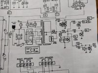
The schematics do not show any clear transformer specs. It does produce various DC voltages using a bunch of resistor divider networks, but the max seems to be 47V (B1 in the diagram). There is also a DC smoothing cap of 50v 6300uF.
There is an odd 6.3v shown on the primary side that goes to the pilot lamps. Not sure what this is ...?
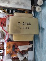
I am attaching a pic of the transformer, and the relevant extract of the power circuit schematic.
The amp specs are 25w into 8ohm per channel.
So... I am looking for some advice on the specs of a replacement transformer. I presume I need 220V : 50-0-50V , and maybe 100VA atleast? The pilot lamps are a confusing element here, but maybe I can build a DC alternative for them, and/or swap to LEDs. Any further info on this 6.3v is helpful.
Or should I junk the whole power section and drive it with a modern power supply to get 47v DC, and let the other voltages stand as they are off the dividers?
Any advice or pointers are much appreciated.
I have chanced upon a faulty Rotel RX 400A
The previous owner said when it was switched on, it briefly lit up (the front illumination) and then smoked and shut down.
On examining the amp, the transformer doesn't seem to be producing any secondary AC - only shows 3VAC.
The schematics do not show any clear transformer specs. It does produce various DC voltages using a bunch of resistor divider networks, but the max seems to be 47V (B1 in the diagram). There is also a DC smoothing cap of 50v 6300uF.
There is an odd 6.3v shown on the primary side that goes to the pilot lamps. Not sure what this is ...?
I am attaching a pic of the transformer, and the relevant extract of the power circuit schematic.
The amp specs are 25w into 8ohm per channel.
So... I am looking for some advice on the specs of a replacement transformer. I presume I need 220V : 50-0-50V , and maybe 100VA atleast? The pilot lamps are a confusing element here, but maybe I can build a DC alternative for them, and/or swap to LEDs. Any further info on this 6.3v is helpful.
Or should I junk the whole power section and drive it with a modern power supply to get 47v DC, and let the other voltages stand as they are off the dividers?
Any advice or pointers are much appreciated.
Attachments
Hi woodyp,
Check the continuity of the transformer primary (mains winding), and the fuses first with the unit unplugged. Also check to make sure you do have your mains voltage across the transformer primary.
Check the continuity of the transformer primary (mains winding), and the fuses first with the unit unplugged. Also check to make sure you do have your mains voltage across the transformer primary.
(some edits for typos and wrong values)
Hello anatech
The fuse is fine and so is the switch. I see 240VAC at the input terminals of the TX (transformer).
I measure almost 15 ohm resistance at the primary.
I also measure c 1.8 ohm at the secondary . I snipped off what look to be the only 4 wires coming out of the TX on the secondary - 2x green and 2x red . The greens mutually, and the reds mutually are continuous, but no continuity between either red to either green. Which makes me think these are two independent secondary coils. The greens must be the pilot lamp ones, the red must be the business ends.
This amp is a pain to disassemble due to all the point to point wires crisscrossing inside - very hard to detach boards to check.
I am testing the amp on a Dim bulb tester. The bulb is completely dead, so I am presuming there is no major short pulling in a lot of amps.
So I am a bit confused as to what's going on here. Everything points to the TX but im not sure in what way it has failed.
Last edited:

Ahh, and we have the first problem with Dim bulb testers. It is dropping the voltage due to excessive current draw, your transformer is probably just fine. A variac would have showed you this without any doubt.
So, you either have shorted outputs or a shorted rectifier most likely. The short may exist in the lamp supply, or the higher power supply to the output stage. C907 could cause this if it shorted.
At this point you don't need to try and power it up. The fault will be obvious once you find it.
So, you either have shorted outputs or a shorted rectifier most likely. The short may exist in the lamp supply, or the higher power supply to the output stage. C907 could cause this if it shorted.
At this point you don't need to try and power it up. The fault will be obvious once you find it.
1 ohm at the primary = Transformer shorted.
Try measuring from one primary to one secondary...... should be open.
Try measuring from one primary to one secondary...... should be open.
Hi Boydk,
Not necessarily true at all. You're jumping the gun here.
Cheaper meters do not read low resistances accurately for starters, and it was a casual connection not using a kelvin lead set I bet. So all we do know is a low primary reading - that's it.
Could the primary be shorted? Sure. But we do not have enough information to conclude this. The OP said it was a pain to get to individual parts and I'll guess the wiring isn't fun to get to. Testing outputs and rectifiers for shorts is easy. If that doesn't pan out, then disconnecting the secondary wires and powering up again through the dim bulb tester is the following step, but we aren't there yet.
Apologies folks, I have made some edits to my post 2, was easier than writing a new post.
May I request you to re-read it for additional details and corrections.
@Boydk this TX has multiple input (primary taps) for selecting various input AC voltages, again with very confusing wiring, so i think the 1ohm was an erroneous measurement. I am more confident in saying its 15ohm on primary.
Primary to secondary is (correctly) open.
Secondary red-red and green-green give about 1ohm.
@anatech I didnt understand your point about the DBT dropping voltage.
I have now isolated the TX from the onward rectification circuits by chopping off the 2 red and 2 green wires I can see (with much effort) coming out of the TX.
I have plugged the unit in directly to power (no DBT)
With the -ve probe on the chassis, and +ve on the input primary side,I get 240vac
I get nothing on either output pair, red-red or green-green, either between the two or with -ve lead on chassis and +ve on either.
Am I doing some thing stupid here?
Hi woodyp,
The "dim bulb" is a highly non-linear resistance in series with your transformer. So when you connect the mains to the unit and bulb in series, they divide the voltage drop depending on current draw of each (the resistance). So if the bulb would normally draw 1/2 ampere (about 100 watts) and your stereo was attempting to draw 5 amperes, most of the voltage would be across the bulb leaving approx 10% for the stereo. The bulb limits current but you never know easily what amount of current is being drawn except it can't be more than the bulb draws on it's own.
The obvious conclusion is that your amplifier current draw it too high, so something draws too much current. Normally that would mean something is shorted, but it could be an open bias circuit causing excessive current draw in the output section. The end result from the perspective of the lamp is the same, excessive current.
Please do not change content in posts that we rely on information from. It throws off all following comments - like you're changing history and it may mislead people. Instead, comment in a post you are correcting information, cut and paste while correcting what you want to change. This is why moderators never change the content of a post unless we are removing personal information for safety sake.
Noted about not editing - didn't think some one would be so quick to reply! thank you for your attention though.
The lamp is not lit, it never showed even the faintest glow. I am acquainted with how it glows in the case of dead shorts or the dim glow when higher powered amps are running. In this case its as if its untouched.
Above I mentioned : I get nothing on either output pair, red-red or green-green, either between the two or with -ve lead on chassis and +ve on either.
I re-measured: I get 3vAC on the geen pair, with -ve on chassis and +ve on either green wire
I get 6vAC on the red pair, again with -ve on chassis and +ve on either redwire
When I switch off power, they go down to 0.
So clearly 'something' is happening on the secondary, but not what it needs to be.
Okay, with secondaries disconnected now. You have very, very little current draw. That is correct and expected. You have continuity in the primary. I would say the transformer is very probably fine.
Unplug and leave things as they are with the power transformer. You'll reconnect it later. One secondary at a time, lamp winding first.
Right now, use the diode check function in your meter. Test the rectifier (dual diode in one package if it is original). Then check each output device, I don't know if it is transistor of chip off-hand. You could post the output section if you have it.
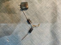
I checked the diodes and it seems it achieves rectification using two diode packages ESAB01N and ESAB01O
Out of which ESAB01N has met with a fiery end, see attached.
The component is described here {https://www.radiomuseum.org/tubes/tube_esab01.html}
ESAB01O checks out fine with a diode test.
I am also attaching the full schematic.
Now it seems the ESAB01N is not in production, so I might have to rig up a pair of diodes in the correct orientation to achieve the same effect?
Attachments

Hi woodyp,
Sure, I would use a pair of 6 ampere diodes connected common cathode. A 200V PIV rating or higher. You can get by with lower PIV, but sometimes the diodes are less expensive at a higher voltage rating, that and the price differential isn't much if any. Headroom won't hurt you ever.
You could also use a bridge rectifier, just use half of it (ignore the negative terminal). It may mount easier, same ratings. Whatever is easier for you to work with.
-Chris
I created a jerry rigged monstrosity using 2x IN5401 as that's all I had to hand.
I left the greens disconnected and isolated.
Hooked up the red secondaries to the new bridge rectifier.
Unfortunately, not much to report. I see no DC. DBT doesn't glow. I still see c 5VAC at the bridge inputs but no DC output.
I checked the output transistors, but they seem to check out in circuit. No shorts.
Scratching my head now.
Attachments
For a 42 VDC supply, a 100 PIV rectifier diode is marginal as heck (I had stronger words). So okay, it didn't fail which is cool. A spike could kill it. That's why I suggested a 200 VDC rating as a minimum.
Never do anything if you don't have the proper parts on hand, or wait for them. Patience.
You went from a bright lamp to nothing. Okay, good. You knew the unit was drawing far too much current. You did find and replace the failed component, excellent. Your readings therefore don't add up. Power transformers often have a thermal fuse in the primary which open if too much heat develops. They can be blown open under some conditions, then the transformer is scrap. However, you measured continuity. A shorted secondary would draw tons of current with the leads disconnected, so that isn't your problem. Therefore, something else is wrong. Now ... what have you done or changed? You disconnected the power transformer secondary windings.
All right, so is the centre tap connected to chassis ground (wherever it was originally)?
Maybe I don´t trust OP´s measuring of primary??
The internal fuse could still be blown.
Woodyp...... Set the voltage swich (if any) on the back to desired voltage. Turn the powerswitch ON.
Measure ohm between the two terminals on the AC-plug. If still 15 ohm´x (or about), primary at least is OK
The internal fuse could still be blown.
Woodyp...... Set the voltage swich (if any) on the back to desired voltage. Turn the powerswitch ON.
Measure ohm between the two terminals on the AC-plug. If still 15 ohm´x (or about), primary at least is OK
Last edited:
@Boydk : I did as you say above,
- the voltage selector switch has a screw to hold it in place, so its set at 240V
-amp power switch on (and yes the switch has been tested
-the main fuse at the back is working and shows continuity across in situ
and ....I get an open circuit. I am genuinely a bit baffled, as I did think I figured out the right terminals in use on the primary to get my 15ohms. So does this definitively mean the primary is blown?
TO answer some of @anatech questions, which in the light of the above might be rendered moot
1/ The DBT bulb never glowed for me -- I mentioned on first power up the amp's fascia pilots lit up but the amp smoked and died. The amp was not on a DBT at that time.
2/ The center tap on the secondary -- I was hunting for that too. I cannot see a center tap wire coming out of the transformer - wondering if the body itself forms the ground as its screwed to chassis?
1.) Measure resistance across the plug where the mains is applied, with the power switch turned on.
2.) The centre tap is normally black and will come out in the same spot as the red wires. If you were to disconnect all the wires, you should always measure an open between any lead and the transformer case or bracket. Your secondary is centre-tapped, so three wires. You have another winding for the lamps which completely independent, but also has one side grounded. That is for your lamps.
2.) The centre tap is normally black and will come out in the same spot as the red wires. If you were to disconnect all the wires, you should always measure an open between any lead and the transformer case or bracket. Your secondary is centre-tapped, so three wires. You have another winding for the lamps which completely independent, but also has one side grounded. That is for your lamps.
I am genuinely a bit baffled, as I did think I figured out the right terminals in use on the primary to get my 15ohms. So does this definitively mean the primary is blown?
You probably didn´t 😉
And yes..... If measured exactly as you described, the primary is blown.
The primary cold be wound in many different ways. 100 + 20 +100 +20 or 110 + 110 + 20 depending on how many wires that comes out.
For instance, I have one right here with 110 + 5 + 5 and 110 +5 +5. Gives you all kinds of opportunities between 110 and 240.
The internal fuse is only built into one of the windings.
Last edited:
- Home
- Amplifiers
- Solid State
- Rotel RX 400A Repair - Transformer problem?