Hi all,
Well, I reckon this is going to be a quite short thread as my feel is that what I am looking for does not exist ... But knowing that there are many knowledgeable people here there might just be someone knowing something about this ...
Is there an ultra-low distortion (<125 dB THD (DC to ~30 kHz), non-GFB, discrete components (non-opamp), non-complex design (basically "not that many components") DAC line level amplification circuitry (gain 5-10x) in existence somewhere accessible? I am asking because MarcelvdG's RTZ FIRDAC design in this post:
https://www.diyaudio.com/community/...t-register-firdac.379406/page-55#post-7419240
shows great potential, however, I would prefer to have the subsequent amplifier be a non-GFB & discrete design (and, yes, there need be filters but "first things first").
Yet I have never seen a non-GFB & discrete design with such low THD values - so my guess is that it doesn't exist ... ? Or may I just have missed it?
Cheers & thanks for reading & maybe replying with good news ;-)
Jesper
Ultra-low distortion (<125 dB THD (DC to ~30 kHz), non-GFB, discrete components (non-opamp), non-complex design cannot exist. Free lunch is not really free.
What does "non-GFB" mean in the context of a subsystem that's already non-global?
I have my own reasons to be wary of routing NFB from the speaker output back to an inverting input. Not least because I consider shaping the output impedance an important part of the design. So a balance has to be struck.
Another reason could be that sprawling complexity may come with various subtle operating weaknesses that don't show up in simulations. E.g. imperfect power rails + class B output stage --> rectified audio with tonnes of harmonics injected onto the rails, which may feed into other parts of the circuit. So a desireable feature may carry a lot of unavoidable baggage to make it bullet-proof and worthwhile.
But if you're looking at a pre-amp stage on its own, I see no obvious reason to avoid GFB. What could be happening for some people is noise or instability or layout errors creating parasitic behaviour. Avoiding NFB is no guarantee of safety.
Hi both - & thanks for considering & replying.
What I was/am hoping for is to see a schematic of a design with the criteria I have listed for a DAC output (i.e. a parallel to an I/V but a V/V so to speak) ... or if this does not exist somehow to confirm that this is the case. I am, I suppose, to a reasonable extent aware that there are many options and considerations to address, however, I essentially am curious to find out how far it is possible to go without global (device-global) NFB in a not too complex circuitry.
Cheers, Jesper
You can have a design with -120dB THD with no GFB but it will necessarily be complex.
You can get rid of the complexity by allowing GFB.
You listed diametrically opposite requirements ;-)
Jan
You can get rid of the complexity by allowing GFB.
You listed diametrically opposite requirements ;-)
Jan
Hi Jan ... & thank you also for replying! ... Well, I realize that the requirements are somewhat contradictory - but I am just trying to find out what is actually possible within the non-GFB "paradigm". With this in mind: Any chance you have a link to (or a name for) the complex -120 dB THD design you mention?
Cheers, Jesper
Cheers, Jesper
Can you be more specific regarding your definition of DAC line-level? Such as, is the circuit really just a line-level preamp stage? Is the DAC I/V (if any) handled outside, or within this circuit? Are the inputs and outputs differential, or single-ended? What is the desired maximum voltage amplitude of the output signal?

Yes, we need to know more specs, especially input and output impedances and voltage levels, and we need to make reasonable constraints. 10x gain is not reasonable.
There's a whole book about that.Hi Jan ... & thank you also for replying! ... Well, I realize that the requirements are somewhat contradictory - but I am just trying to find out what is actually possible within the non-GFB "paradigm". With this in mind: Any chance you have a link to (or a name for) the complex -120 dB THD design you mention?
Cheers, Jesper
https://www.amazon.com/Audio-Power-Amplifiers-Towards-Inherently/dp/9490929158
Jan
I don't think discussion of DAC is very relevant to OP's quest. MarceldvG's RTZ dac mentioned in OP has differential and single-ended outputs. My version (measured in OP link) has 4 Vrms output differential and 2 Vrms output single-ended. Output impedance is determined by the series output resistor which in my version is 100 ohms. So nothing out of the ordinary.Can you be more specific regarding your definition of DAC line-level? Such as, is the circuit really just a line-level preamp stage? Is the DAC I/V (if any) handled outside, or within this circuit? Are the inputs and outputs differential, or single-ended? What is the desired maximum voltage amplitude of the output signal?
Hi Ken ... & I can see that others have posted during my writing ... thanks all for chiming in ;-).
I am interested in finding out if there is a discrete & non-GFB alternative to MarcelvdG's FIRDAC output stage as shown here:
https://www.diyaudio.com/community/...t-register-firdac.379406/page-11#post-7174367.
Bohrok2610 mentions the specs - to this I can add that the output impedance from the FIRDAC itself is 375 ohms and to my memory the output level from the FIRDAC itself is around 0.9 Vrms. Basically it is a differential output from the FIRDAC.
Maybe I should also mention that implementing a fourth-order filter (DSD LPF) around this amplifier circuitry will be required. From my measurements the high sound quality filters in HQPlayer (ASDM7 etc., as I understand it) have a rising noise level from ~60 kHz so I would personally set the low-pass frequency to be around this frequency.
I chose a 10x gain as a safeguard against low-level recordings. Maybe it can be lower in practice (x4 possibly?) - at least for normal recordings ...
@jan: Ha-ha ;-) ... I thought you were thinking about Kolinummi's book! As it is I already have it, and I think there are some circuits here that would fit the bill - except, as you have already mentioned - the IMHO rather high level of complexity.
So, if possible, I would prefer to find a simpler alternative, if at all possible ... ?? Please note that I am not considering venturing into a design phase with my question - just trying to find out if a circuitry that fits the above mentioned bill actually exists.
Best wishes for your day - Jesper
CCS thermally compensated with a cascode?
I searched for thermal distortion and finally stumbled upon a missing puzzle piece that ties a lot of loose ends together.
peufeu -- memory distortion
Very enlightening!
Tube input stage; thermally compensated V8 gain engine... 100dB NFB... 😎
I searched for thermal distortion and finally stumbled upon a missing puzzle piece that ties a lot of loose ends together.
peufeu -- memory distortion
Very enlightening!
Tube input stage; thermally compensated V8 gain engine... 100dB NFB... 😎
Think about your gain staging. Maybe you could add the gain somewhere else...
What is it that you really try to avoid or gain or achieve?
//
What is it that you really try to avoid or gain or achieve?
//
The answer to the original question is "no", you need overall feedback for ultra-low distortion, or possibly a vastly over-powered amp stage such that normal line-level counts as a tiny signal level (think 1000V supply rails!!). Complex allows better performance, more is definitely more, but it has to be the "right more"! I'm assuming ultra-low is talking about -110dB or better (in the ppm class).
Fortunately its all been done for us, witness the performance levels of something like the OPA1612. So the complex route is actually very simple in practice!
Fortunately its all been done for us, witness the performance levels of something like the OPA1612. So the complex route is actually very simple in practice!
Is there an ultra-low distortion (<125 dB THD (DC to ~30 kHz), non-GFB, discrete components (non-opamp), non-complex design (basically "not that many components") DAC line level amplification circuitry (gain 5-10x) in existence somewhere accessible?
High grade 1:5...10 step-up transformer.
Good ones can do way below -120dB THD, bandwidth to 100kHz+.
No op amps. Single component.
Design the secondary load so that 100pF...330pf cable capacitance and 10k...50k give a correctly damped flat frequency response.
That usually means adding a capacitor and resistor (Zobel) across the secondary. Add a cap and resistor to the primary to get levels and roll-off right.
5 components in total.
Thor
I took a look at Marcel’s FIRDAC schematics which you linked, but, on only a too quick review, the circuit appears not so simple. Being lazy by nature, I didn’t take the time or effort to accurately determine the answers to all of those specification questions I had asked about in my last post.
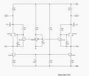
That said, I’m including the schematic of a rather elegant, fully discrete circuit. It is fully differential (and can simply be cut in half if only SE operation is required). Incorporates the DAC I/V function (since it is an I/V circuit). Doesn’t utilize GFB, but does use short local FB loops. Features a differential output impedance of essentially 780 Ohms, and half of that if operated SE (the values of which are inversely adjustable against the gain). It does all of that with only 7-transistors, 6-capacitors (including a 1st order reconstruction filter) and 9-resistors.
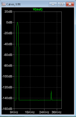
It was designed by diyAudio contributor Sergio Santos (smms73), so ALL credit goes to him. It was originally intended for use with the popular PCM179X family of differential current-output DAC chips. The other image is a simulated distortion spectrum of the circuit with a demanding 10kHz input signal, it looks like. It features the sort of figures you were hoping for. Another desirable aspect of the circuit is that, because of the local FB, the distortion performance is not based on close matching of the transistors, as would be required for an open-loop circuit. You will have to do the work of determining whether, or not, this is suitable to your specific application.
That said, I’m including the schematic of a rather elegant, fully discrete circuit. It is fully differential (and can simply be cut in half if only SE operation is required). Incorporates the DAC I/V function (since it is an I/V circuit). Doesn’t utilize GFB, but does use short local FB loops. Features a differential output impedance of essentially 780 Ohms, and half of that if operated SE (the values of which are inversely adjustable against the gain). It does all of that with only 7-transistors, 6-capacitors (including a 1st order reconstruction filter) and 9-resistors.
It was designed by diyAudio contributor Sergio Santos (smms73), so ALL credit goes to him. It was originally intended for use with the popular PCM179X family of differential current-output DAC chips. The other image is a simulated distortion spectrum of the circuit with a demanding 10kHz input signal, it looks like. It features the sort of figures you were hoping for. Another desirable aspect of the circuit is that, because of the local FB, the distortion performance is not based on close matching of the transistors, as would be required for an open-loop circuit. You will have to do the work of determining whether, or not, this is suitable to your specific application.
Attachments
Last edited:
Hi all - & many thanks for your many and varied feedbacks 😉 I will reply to each of you below:
@thorstenlarsen : Well, I honestly did not have a tube design in mind (and I would be reluctant to make it a tube design) ... but you would say that in this way it would be possible to reach - 125 dB THD? Just out of curiosity: if you have a link to such a design I would like to see it ...
@abstract: I will allow myself to turn my reply to your post upside-down and consider the last part first: You write: " 100dB NFB... 😎 "... Just to make sure: you have seen that I would be interested in reaching - 125 dB THD so as to complement the ~-127 dB THD of Marcel's DAC?
And then, regarding thermal distortion, I may mention that there's also a section about this in Kolinummi's book that Jan Didden and myself mention above. Actually quite a significant distortion contributor if I remember correctly ...
@TNT: I would like to achieve the full sonic qualities of Marcel's circuitry - including the low distortion level (even if at this point in time I personally do not know where the level for non-audibility is). And then in a non-complex & non-GFB circuitry that translates the output level of Marcel's circuitry to a filtered line level.
@Mark Tillotson : Hmmm ... I have to admit that opamps, at least for now, are not my main area of "knowledge". But I am trying them out for the time being (aot the OPA1612, OPA828) to learn more about the current state of opamp design. If they prove sound-wise overall "better" than the discrete circuitry I know of it will (indeed) make some things easier ...
@ThorstenL : Very interesting suggestion ... I admittedly have been a bit wary of transformers because the notion of very long wires and transformer "challenges" like hysteresis and low/high frequency cut-offs have not been (are) not that appealing to me. Nevertheless ... might you have a suggestion for a transformer that would be very best quality SQ-wise? It could be interesting to see what may be possible ..
@Ken Newton : Thank you also for your feedback & pictures. As it is I actually have used the more basic variant of Sergio's circuitry - the common base coupling - for years now exactly in relation to the PCM1794. In this context, as I reckon you already know, it is capable of extraordinary performance depending on the voltages and currents used (the R1,R4 resistor value) - potentially outperforming the PCM1794 by a good margin.
I have also considered the common base (and a Sziklai circuitry similar to Sergio's) in this context, however, as I have been thinking about it there are a couple of additional factors to include with Marcel's DAC:
- Marcel's DAC has an output impedance of 375 ohms. This means that the very high output impedance of the PCM1794 (apparently several hundred kiloohms) is not available to offset the BE distortion of the "generic" common base structure. Adding the Sziklai may reduce the input impedance of this generic common base structure (as you likely know) - thus reducing the distortion level - but if one is also to run a bit of current through the "steering transistors" of the Sziklai (here Q1 and Q3) while reducing the distortion using the Sziklai - the current through the Sziklai structure as a whole may become quite high. Which again may mean low output levels from the Sziklai ... (as i mentioned above it would be ~1.26Vp from Marcel's DAC and to compensate for low-level sound source material I would prefer it to be maybe 5Vp). In order to keep distortion reasonably low (I have not simulated this specifically but from memory of previous simulations) assuming a factor of 6 in the Sziklai (Q1 & Q3 5mA and Q2,Q4 30 mA) this would mean a R1/R4 resistor of 1k5 and a voltage drop of ~52 volts across these resistors alone. While doable I ended up hoping that that a more, well, straightforward solution might be possible ..
- Also, in my measurements on Marcel's DAC (and NoDAC approaches) I have noticed that there is a quite noticeable HF noise rise above, say, 55 kHz when using HQPlayer. A bit depending on the DAC in question it may reach -100 dB in frequencies not too distant from what I would assume are normal amplifier frequency ranges. Thus, personally, I would consider good HF filtering to be "important" ... One way of doing this could be to add an R/C cut-off between Marcel's DAC and the Sziklai circuitry, however, depending on the cut-off frequency chosen, this lowers the HF impedance seen by the Sziklai and thus increases its HF distortion level. One might then add a resistor in-between this capacitor and the Sziklai's input (thus DAC's 375 ohms -> capacitor -> added resistor -> Sziklai) but then the output impedance of Marcel's DAC goes up meaning that the Sziklai's amplification goes down, etc., etc. ...
So while this circuitry is still under consideration I am a bit unsure as to whether it/I will eventually be able to make it work in this context. Yet a fine suggestion - thanks!
Well, no further words for now - have a fine day ;-)
Jesper
At the level of the Marcel DAC, it is already very hard to sort out what references you should have to evaluate this product that you wish to "improve". Yes, note the citation marks... as this is exactly my point here.... I suppose you have heard it!? And you where not satisfied with the result or at least thought it need improvement. What did you not like? How did you deduct that this anomaly is tied to the output stage? With what equipment did you evaluate and identified this anomaly? Perhaps once you connected a really clean DAC into your system, other characteristcs was suddenly reviled?
Wouldn't it be fair that you had a solid thesis and an actual identified problem before you engage your back-office expert panel into deep thinking and work. And there is already a three where this fine design is "shredded" to pieces - why didn't you just add to that choir? Were your ideas so superior that it needed an own thread? - Dalai don't like....
Also, pointing out a fellow members design as something that need immediate improvement is not so nice behaviour I think... especially when one self is not able to do the improvement. You could have started the thread with just defining the source and sink electrical characteristics and ask for help of an amplifier with certain characteristics (this you did) to connect them without pointing out an a specific product. But maybe you are not able to do even this.. but you know to diss NFB...
Anyways... good luck - you will need it...
//
Just to avoid misunderstandings: I don't mind at all when people try to come up with alternative output filters for my DAC. In fact, it is one of the reasons why the filter board is separate from the main board.
- Home
- Source & Line
- Digital Line Level
- Ultra-low distortion, non-GFB, discrete, non-complex, DAC line level amplification ... does it exist?