Actually, you don't need the vastly overrated amp.
There are circuit techniques to keep the voltage across and/or the current through devices as constant as possible, which avoids most of the distortion.
The book I mentioned before is about that and achieves similar distortion figures as a GNFB amp with a bit more complexity in the form of some additional passive and small-signal active devices.
Jan
OK - so I retract my previous critique... but perhaps the gist of my post is something to think about in general...Just to avoid misunderstandings: I don't mind at all when people try to come up with alternative output filters for my DAC. In fact, it is one of the reasons why the filter board is separate from the main board.
//
@ThorstenL : Very interesting suggestion ... I admittedly have been a bit wary of transformers because the notion of very long wires and transformer "challenges" like hysteresis and low/high frequency cut-offs have not been (are) not that appealing to me.
Do you realise how many transformers most recordings passed through? Starting with the one inside the microphone?
Nevertheless ... might you have a suggestion for a transformer that would be very best quality SQ-wise? It could be interesting to see what may be possible ..
Readily available.
https://www.jensen-transformers.com/wp-content/uploads/2014/08/jt-13k7-a.pdf
Not very low distortion, you need a bigger core for that. But it gives you an idea how transformers behave.
S&B TX-103 would be my recommendation, but it's no longer available at sensible cost.
- Also, in my measurements on Marcel's DAC (and NoDAC approaches) I have noticed that there is a quite noticeable HF noise rise above, say, 55 kHz when using HQPlayer.
Look up noise shaping.
Thor

I think its nice of gentlevoice to make hiis own thread and Marcel does take it as critisism. I dont see it as such myself. We are free to contribute to the thread or choose not to. He is not even claiming to be able to improve. Only airing his ideas.At the level of the Marcel DAC, it is already very hard to sort out what references you should have to evaluate this product that you wish to "improve". Yes, note the citation marks... as this is exactly my point here.... I suppose you have heard it!? And you where not satisfied with the result or at least thought it need improvement. What did you not like? How did you deduct that this anomaly is tied to the output stage? With what equipment did you evaluate and identified this anomaly? Perhaps once you connected a really clean DAC into your system, other characteristcs was suddenly reviled?
Wouldn't it be fair that you had a solid thesis and an actual identified problem before you engage your back-office expert panel into deep thinking and work. And there is already a three where this fine design is "shredded" to pieces - why didn't you just add to that choir? Were your ideas so superior that it needed an own thread? - Dalai don't like....
Also, pointing out a fellow members design as something that need immediate improvement is not so nice behaviour I think... especially when one self is not able to do the improvement. You could have started the thread with just defining the source and sink electrical characteristics and ask for help of an amplifier with certain characteristics (this you did) to connect them without pointing out an a specific product. But maybe you are not able to do even this.. but you know to diss NFB...
Anyways... good luck - you will need it...
//
Cheers!
Marcel does take it as critisism
Do I? In any case, even if I did, it wouldn't matter.
One of the proposed circuits features current followers to be put between the DAC core and the reconstruction filter. There is an exotic type of translinear current follower that might be useful for that application; it uses several kinds of feedback, both positive and negative, but I think those all count as local. If I'm not mistaken, it's called a crossquad, although that term usually refers to something else, namely a common-centroid layout technique.
When Q1 matches Q2 and Q3 matches Q4 and they all have reasonably high hFE, the voltage at the input is determined by voltage source Vbias. That is, the input voltage is Vbias + vBE,Q3 + vBE,Q2 - vBE,Q4 - vBE,Q1. As Q2 and Q1 run at essentially the same current and the same holds for Q3 and Q4, the base-emitter voltages ideally cancel. Finite hFE and Early effect and self-heating in Q2 can still spoil it to some extent.
When you choose Vbias > 2.48 V, for example equal to the 4.96 V reference, there will always be a net current flowing out of the emitter of Q1. That's obviously necessary to make it work.
There is good critique and bad critique... which one did you have in mind? 🙂and Marcel does take it as critisism
I think we can leave this - all OK... 🙂
//
Folks Im sorry! The "not" was missing in that sentence. Or I tried to write doesn't and got auto corrected. Sorry for not reviewing before posting🫢
Regarding good step up transformers, one downside is that they are not necessarily low cost. One that is getting pretty good reviews is the Quadratic Audio MC-1:
https://www.ttvjaudio.com/Quadratic-MC-1-Moving-Coil-Transformer-p/qua0000001.htm
https://forum.audiogon.com/discussions/review-of-quadratic-mc-1-sut-with-comparisons-to-other-suts-2
In the interests of disclosure, one of the designers is a friend as well as a member of this forum.
https://www.ttvjaudio.com/Quadratic-MC-1-Moving-Coil-Transformer-p/qua0000001.htm
https://forum.audiogon.com/discussions/review-of-quadratic-mc-1-sut-with-comparisons-to-other-suts-2
In the interests of disclosure, one of the designers is a friend as well as a member of this forum.
Last edited:
@TNT : I can see that Marcel has replied to your post #19 with his feedback, so I will just briefly reply here to the part of your post that relates to me - and then otherwise not comment further on this:
- When I re-read what I have written about Marcel's DAC (& output stage) in this thread I cannot see that I have been criticizing his design. On the other hand in post #1 I write " I am asking because MarcelvdG's RTZ FIRDAC design in this post: ......... shows great potential ", and a bit later:
" however, I would prefer to have the subsequent amplifier be a non-GFB & discrete design " ... The word I use here is "prefer" which is not a criticism of Marcel's design but indicating my own preference towards a discrete design.
- To my memory Marcel at some point in the RTZ FIRDAC thread specifically mentions that by posting the design in the thread he is also inviting comments & suggestions (please correct me, Marcel, if you read this and disagree ... ).
- In general I hope Marcel will connect with me personally should I at some point in time (and this would be unintentionally) say or do things in relation to him, his designs, or posts in general, that are not feasible to him.
On a personal note the way I interact with others here (or people in general) matters to me. As I see it it is much more pleasant, and in my experience also conducive to a subject in question, if the talk/discussion/exchange of experiences, ideas & views can be done in a mutually agreeable and respectful tone.
I have read your post #26, TNT, and now I will leave this subject.
Regarding the replies that have come during the day, then thanks again for replying ;-) ... I can say that I will have a busy evening but I hope to take a look at them some time in the morning.
Best regards,
Jesper
Forgot to mention that this is a balanced version of the crossquad current follower. It only works well for differential currents. For common-mode currents, it is equivalent to just a pair of plain old common-base stages (Q2 and Q4) with diode-connected transistors in series with their inputs (Q1 and Q3).

Regarding good step up transformers, one downside is that they are not necessarily low cost. One that is getting pretty good reviews is the Quadratic Audio MC-1:
Mark, are these transformers available as raw parts?
I didn’t notice them being offered as such in the links you provided, only as finished enclosed products.
No. They are exclusive to Quadradic at least for now. Presumably the same thing for Quadradic products that may follow. IIUC developing the transformers required a lot of work including building multiple prototypes and lot of skilled listening tests (again IIUC, Cinemag was tasked with developing something new, something challenging, and something not necessarily low cost to manufacture). In addition, there are worldwide Quadratic distributors and dealers that have to make a living. Nobody is getting rich; that I know for a fact. Its that high end tends to be a rather low-volume market. That combined with higher manufacturing costs for special/custom components tends to make some products costly. I wish it were otherwise.
Last edited:
I was looking for something similar but more for buffering the DAC to drive two devices ( headphone amp, and preamp). I am going to give this a try https://www.diyaudio.com/community/threads/jhoflands-diamond-buffer.401231/ .
Hi all,
& thanks again for your many & fine suggestions.
I have had a bit of time today to look at the different circuitries and to my eyes the common base versions (Sergio/Ken Newton, my own, Marcel's variant) seem quite interesting as they are low parts count, an approach that appears potentially good sounding, and can be very low distortion. Particularly the version suggested by Marcel in #30 simulates very well indeed - depending on the transistors used, output level etc., the THD may be around -140 to - 160 dB ... (It is a simulation so some care to be taken in interpretation of the THD level, as I understand it).
I also did try to simulate this circuitry with some HFE variation between the various transistors used, and the circuitry still simulates very well. The "only" (?) caveat that I could identify with all of these "common base" versions was that the output noise will be rather high because the resistor values in the RTZ DAC parallels down to 375 ohms which causes a quite high noise level on the output.
Would any of you have an impression of the sound quality e.g. of the circuitry in #30? Any issues, sound-wise?
@ThorstenL & Markw4 : Thank you both for suggesting and linking to these transformers. It appears to be an interesting option, however, my budget actually is quite limited so maybe it most feasibly is something to possibly explore at a later point in time ... BTW do you know about SAMAR Audio's transformers? Should be very high sound quality and appear to be not too expensive - I have not tried them myself, though.
https://www.samaraudiodesign.com/categoryTransformers.html
@jan.didden : Jan, I reckon there may be interesting circuits to explore in Kolinummi's book. And it is some years back that I read it so if time allows I may look at it again. Thanks for bringing it to my attention 😉
@wirewiggler : Thanks also for replying & linking to the diamond buffer circuitry. It could be interesting - but apart from placing a filter on the input the "interior" of the circuitry is at quite low impedance levels - which I reckon could make filtering of the DSD signal a bit challenging. So I am not sure it would work in this context (may be someone else knows differently?) Yet thanks for mentioning it!
Again thank you all for considering & replying!
Cheers, Jesper
& thanks again for your many & fine suggestions.
I have had a bit of time today to look at the different circuitries and to my eyes the common base versions (Sergio/Ken Newton, my own, Marcel's variant) seem quite interesting as they are low parts count, an approach that appears potentially good sounding, and can be very low distortion. Particularly the version suggested by Marcel in #30 simulates very well indeed - depending on the transistors used, output level etc., the THD may be around -140 to - 160 dB
... (It is a simulation so some care to be taken in interpretation of the THD level, as I understand it).I also did try to simulate this circuitry with some HFE variation between the various transistors used, and the circuitry still simulates very well. The "only" (?) caveat that I could identify with all of these "common base" versions was that the output noise will be rather high because the resistor values in the RTZ DAC parallels down to 375 ohms which causes a quite high noise level on the output.
Would any of you have an impression of the sound quality e.g. of the circuitry in #30? Any issues, sound-wise?
@ThorstenL & Markw4 : Thank you both for suggesting and linking to these transformers. It appears to be an interesting option, however, my budget actually is quite limited so maybe it most feasibly is something to possibly explore at a later point in time ... BTW do you know about SAMAR Audio's transformers? Should be very high sound quality and appear to be not too expensive - I have not tried them myself, though.
https://www.samaraudiodesign.com/categoryTransformers.html
@jan.didden : Jan, I reckon there may be interesting circuits to explore in Kolinummi's book. And it is some years back that I read it so if time allows I may look at it again. Thanks for bringing it to my attention 😉
@wirewiggler : Thanks also for replying & linking to the diamond buffer circuitry. It could be interesting - but apart from placing a filter on the input the "interior" of the circuitry is at quite low impedance levels - which I reckon could make filtering of the DSD signal a bit challenging. So I am not sure it would work in this context (may be someone else knows differently?) Yet thanks for mentioning it!
Again thank you all for considering & replying!
Cheers, Jesper
Is there an ultra-low distortion (<125 dB THD (DC to ~30 kHz), non-GFB, discrete components (non-opamp), non-complex design (basically "not that many components") DAC line level amplification circuitry (gain 5-10x) in existence somewhere accessible? I am asking because MarcelvdG's RTZ FIRDAC design in this post:
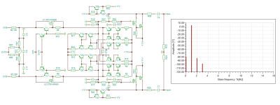
Well, for a number of reasons I dug out some old design for an AMR product that never got released. It shows reasonably well what non loop NFB not excessively complex can do. Now note, I am not simulating a circuit fragment, but a complete practical circuits.
It's for a discrete FIR DAC (not exactly MvG's on, but similar enough).
The I/U conversion uses a BJT/FET Sziklai followed by a bunch of current mirrors that split and mix the currents, to create two single ended outputs that mix the two output current phases and allow also balanced out. Followers are added (FET Sziklai aka inverted Darlington), as otherwise output impedance is rather high.
The followers together with I/U conversion resistors and the other RC form a 3rd order LPF, 20Hz-20kHz is +0/-0.05dB or better flatness, at the cost of a ~190khz -3dB point, which is rather high given noise shaping in the DSD Source. Attenuation at around DSD256 sample frequency is ~110dB.
Parts values / types values are no shown, but should be obvious / easy to calculate.
Sim suggests ~-90dB H2 for 0dBFS and SE out. Balanced cancels H2 and leads to lower THD but not really lower audible distortion. Non of the obvious tweaks to the circuit such as cascoding etc. offer any tractability in getting seriously lower HD. SNR looks 116dB unweighted re. 2V SE / 4V BAL.
In listening tests the results of the prototypes where excellent, there the followers were Tube Cathode follower.
I'd be interested to see circuitry that is more simple, higher performance or both.
While -90dB H2 is not hard, -120dB seems a trifle challenging.
Thor
Attachments
Last edited:
@ThorstenL: Thanks for considering & taking the time to post! However, I think it may be most feasible to be honest and say that the circuitry you suggest falls outside the scope of what I am looking for both in terms of THD & complexity.
BTW ... This morning I happened to think about possible solutions and remembered the so-called Kulish structure (the schematic is on the previous page at the bottom):
https://www.diyaudio.com/community/threads/single-darlington-line-preamp.74861/page-4
Only two transistors, "high" input impedance & single-ended it reaches ~ -135 dB 2H in simulation. In practice though it may require a relatively high supply voltage and the DC voltage output level from the RTZ FIRDAC is a little lowish to optimize the error correction of this circuitry - it probably would require a smallish negative voltage supply as well to allow for resistor values of suitable sizes. But maybe an option ... ?
BTW Thorsten ... May I ask you is you have a practical best SQ quality component solution for the 220uH inductor you suggested in your circuitry in this post:
https://www.diyaudio.com/community/...-register-firdac.379406/page-108#post-7614959
It seems to me that except for the 1812CS series from coilcraft there are not really any inductors with non-magnetic cores (and the maximum value of the 1812CS series is 33uH & appr. 13 ohms DC resistance) with such high inductance values.
https://www.mouser.dk/datasheet/2/597/1812cs-3084351.pdf
Cheers, Jesper
@ThorstenL: Thanks for considering & taking the time to post! However, I think it may be most feasible to be honest and say that the circuitry you suggest falls outside the scope of what I am looking for both in terms of THD & complexity.
What I show is relatively low complexity. As for matching simulation and real device, back when Neil Young was riding through the desert on a Pono with no name, late Charles Hansen of Ayre designed the output stage using mostly current mirrors and current conveyors. Measurements are here:
https://www.stereophile.com/content/pono-ponoplayer-portable-music-player-measurements
Realistically simple circuits without global looped feedback never have low THD at the levels you are asking for.
BTW ... This morning I happened to think about possible solutions and remembered the so-called Kulish structure (the schematic is on the previous page at the bottom):
https://www.diyaudio.com/community/threads/single-darlington-line-preamp.74861/page-4
Only two transistors, "high" input impedance & single-ended it reaches ~ -135 dB 2H in simulation.
Build it, measure it. MY simulation suggests a much worse performance.
MIND YOU, for such a simple circuit the result is not bad.
Over the years I used TINA to simulate 100's of circuits that were also build and measured on AP2 and sold in commercial products others measured. I have relatively confidence in the results as USUALLY there is close agreement between Sim and real circuit and finding out the why, when there are gross differences is usually educational.
BTW Thorsten ... May I ask you is you have a practical best SQ quality component solution for the 220uH inductor you suggested in your circuitry in this post:
https://www.diyaudio.com/community/...-register-firdac.379406/page-108#post-7614959
I routinely use TDK or Tayo Yuden or equivalent 12mm surface mount choke coils. These rare typically rated for many ampere before saturation and I generally have them in circuits where there is deliberately DC current significantly in excess of peak-peak signal current. I found the results transparent on AP2.
https://www.diyaudio.com/community/...-register-firdac.379406/page-108#post-7614959
It seems to me that except for the 1812CS series from coilcraft there are not really any inductors with non-magnetic cores
Just choose the right core and application. And test.
Good test gear is SO CHEAP and SO ACCESSIBLE these days, there is little excuse not to have a basic set, no need to spring for an AP2.
Thor
Forgot to mention that this is a balanced version of the crossquad current follower. It only works well for differential currents. For common-mode currents, it is equivalent to just a pair of plain old common-base stages (Q2 and Q4) with diode-connected transistors in series with their inputs (Q1 and Q3).
View attachment 1284880
I just want to mention that this an excellent little circuit. Thank you.
Thor
@ThorstenL : Hmmm, well, it still is not quite the type of circuitry I am looking for but who knows - maybe some day it may come more into vogue ...
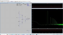
Regarding the Kulish circuitry I linked to, in LTSpice it simulates to ~-122 dB 2H with the setup shown in the link (see attachment). Output level 4Vpp. However, other transistors simulate better than the 2N3904s.
In practice I have found it to be capable of at least - 108 dB 2H - but in a suboptimal measurement setup so I wouldn't be surprised if it did better than that in a more optimized setup. One advantage of this circuitry I have noticed though, besides low component count and single-ended performance, is that it appears to be almost unaffected by the load impedance it looks into. On the other hand it is quite sensitive to temperature variations and the actual precise value of the resistors used. Even very low changes in both temperature & resistance values may cause significant changes of distortion levels. So IMHO a somewhat "picky" circuitry.
Thanks also for the hints on coils and how to use them 😉 An option to consider I think ...
And, yes, it is fine that e.g. something like the Cosmos ADC has now become available - makes measurements much more of a joy, as well as genuinely informative at very low distortion levels.
Cheers, Jesper
Attachments
- Home
- Source & Line
- Digital Line Level
- Ultra-low distortion, non-GFB, discrete, non-complex, DAC line level amplification ... does it exist?