If your simulated THD results vary considerably with transistor type, don't trust it.
It points to less than realistic models.
Jan
It points to less than realistic models.
Jan
@gentlevoice : why do you chase ultra low distortion? I prefer euphony over parameters, but it's just me.
Try using better model for 2N3904. E.g. Bob Cordell's. Results will be similar to what ThorstenL showed.Regarding the Kulish circuitry I linked to, in LTSpice it simulates to ~-122 dB 2H with the setup shown in the link (see attachment). Output level 4Vpp. However, other transistors simulate better than the 2N3904s.
@ThorstenLRegarding the Kulish circuitry I linked to, in LTSpice it simulates to ~-122 dB 2H with the setup shown in the link (see attachment). Output level 4Vpp. However, other transistors simulate better than the 2N3904s.
I simply put the circuit into TINA as shown. It simulates as I show.
Knowing what I know about practical circuits I think TINA is on the money and why Switchercad is one to two decades out of the ballpark may relate to the simulation engine or how well the transistor models are made. Simulators are only as good as the models and underlying math,
In practice I have found it to be capable of at least - 108 dB 2H -
Interesting. With 2N3904? Without trimming resistors just so? Do you have any posting about this?
Also, which resistor needs trimming to get the minimum H2. I'm open to see if tweaking this in TINA, which has different models, gets a better result.
Thor
This is high quality mic transformer i used in F1J.
https://www.diyaudio.com/community/threads/firstwatt-f1j.169509/post-6599536
https://www.diyaudio.com/community/threads/firstwatt-f1j.169509/post-6599536
Here is another mic transformer, much cheaper option if you can find it. RadioShack.
https://www.diyaudio.com/community/...former-volume-control-tvc.393872/post-7615457
https://www.diyaudio.com/community/...former-volume-control-tvc.393872/post-7615457
Hi all,
& thanks again for considering & replying ...
Regarding the Kulish circuitry as I mentioned it is quite picky with regards to parameters so I would not expect a different model to give the same result in simulation. I have attached a simulation where I use Cordell's spice models and have made a preliminary optimization of the typically relevant resistor (318 ohms in the link I posted). With this optimization the distortion drops from - to my memory - ~85 dB 2H to ~-115 dB 2H. Again done in LTSpice.
As you can see it is quite discerning regarding the correct resistor value and on my PCB I mounted a trimmer to be able to fully optimize the distortion level. Then I intended to subsequently replace the trimmer with fixed resistors. I don't have any precise recollection of which transistor combination achieved the -108 dB 2H but it probably was something like the 2SC3324 or its newer successor. And again, the setup was not optimal so I would not be surprised if it was possible to achieve a better result.
@adason : Thanks for replying and linking to the transformers ... I will keep them in mind - but as I wrote in my previous post I have decided to wait with exploring this field - already much to do ;-)
@lcsaszar : Hmmm ... thanks for your question. I hope it is ok with just a brief reply: I prefer to be able to dive into music's fine nuances and in my experience lowering the distortion level improves this ability. I reckon there will always be some degree of euphony (distortion no matter its level will "change"/"euphonize" the sound), however as I see it/experience it, with lower distortion levels this "coloring" may just become less obvious. I know this has been debated extensively in these forum so just my IMHO & personal observation (and I admittedly am not really interested in going deeper into this). What prompted my current interest in low distortion was Marcel's DSD FIRDAC which shows very low distortion levels and thus - from my point of view - great potential e.g. with a (for me preferably) discrete output stage.
@jan.didden : Thanks also for commenting. It sounds feasible but I am also thinking that it depends on the parameters involved with optimizing the circuitry in question ... ? E.g. the common base circuitries mentioned earlier in this thread clearly benefit THD-wise from transistors with low Rbb - and in simulation the results may vary quite some depending on the transistor used. But in general practice has taught me to be a bit cautious with reliance on the distortion simulation results in LTSpice - IME they can be somewhat different from reality.
Just FYI I have a busy day so will not reply more today - but of course feel welcome to continue as you wish ...
Have a fine day, all of you ...
Jesper
Attachments
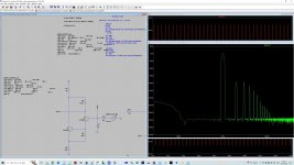
Ok, so I had another go.
I added the minimum components to make it a practical amplifier.

So yes, we can cancel H2 ( I suspect with more effort to zero).
However the resistor value that does this is very precise. Being of 0.3% either side means the cancellation effect is gone. Changing simulation temperature a few degrees also changed HD considerably.
Rise of HD with frequency is also considerable:

I suspect to actually get such performance in practice means trimming and frequency compensating each amplifier and operating in a temperature controlled environment.
I have used similar types of distortion cancellation previously in SE Tube amplifiers. Subjectively the results were not to my liking.
I wish you all the best with this, hope it all works out to your liking.
Thor
I added the minimum components to make it a practical amplifier.
So yes, we can cancel H2 ( I suspect with more effort to zero).
However the resistor value that does this is very precise. Being of 0.3% either side means the cancellation effect is gone. Changing simulation temperature a few degrees also changed HD considerably.
Rise of HD with frequency is also considerable:
I suspect to actually get such performance in practice means trimming and frequency compensating each amplifier and operating in a temperature controlled environment.
I have used similar types of distortion cancellation previously in SE Tube amplifiers. Subjectively the results were not to my liking.
I wish you all the best with this, hope it all works out to your liking.
Thor
@ThorstenL : This is just for completeness ... I posted the Kulish circuitry as a feedback to this sentence of yours:
As it is I have not done extensive listening on this topology, so I am a bit careful with saying much about its possible sonic signature. Yet as I mentioned I personally consider it a bit "picky" in terms of resistor values & thermal drift. However, when measuring it in practice, which involved setting and leaving the trimmer as it was & switching the circuitry on/off it actually did prove quite stable in terms of reproducible performance.
I think that one potential advantage of this circuitry is that by adjusting the resistors it is possible to quite easily adjust the harmonic distortion profile so as to listen to the impact of this while keeping the overall distortion level reasonably at the same level.
Anyway, will leave this topology here.
& likewise to you - Jesper
I'd be interested to see circuitry that is more simple, higher performance or both.
As it is I have not done extensive listening on this topology, so I am a bit careful with saying much about its possible sonic signature. Yet as I mentioned I personally consider it a bit "picky" in terms of resistor values & thermal drift. However, when measuring it in practice, which involved setting and leaving the trimmer as it was & switching the circuitry on/off it actually did prove quite stable in terms of reproducible performance.
I think that one potential advantage of this circuitry is that by adjusting the resistors it is possible to quite easily adjust the harmonic distortion profile so as to listen to the impact of this while keeping the overall distortion level reasonably at the same level.
Anyway, will leave this topology here.
I wish you all the best with this, hope it all works out to your liking.
& likewise to you - Jesper
Chasing at all costs the smallest possible distortions and avoiding the global NFB is not really that important. It's especially pointless to chase ultra small distortions that we can't hear at all even though they're 100x louder.
I made the Aikido tube preamp many years ago. The sound was absolutely OK, but the voltage amplification was terrible, 15-18x depending on tubes i used (E88CC, 6922, 6N23P,5670, 6CC42 and similar). The useful part of the potentiometer scale was 25%. I take it out of the box and put in Aikido cathode follower, total NFB, low THD & noise, no gain no pain. The sound is better, of course, and the potentiometer now goes over half the scale. The unfortunate Aikido languished in some plastic box. Last year I tried on Aikido again, to introduce global NFB, reducing the amplification to 2.5x. To my surprise, the sound improved a lot, got a wider frequency range, less THD & noise and lower output impedance. So global NFB can be both a good and a bad thing, it all depends on the specific case. Now I got a nice box for Aikido, to put it back into use.
I made the Aikido tube preamp many years ago. The sound was absolutely OK, but the voltage amplification was terrible, 15-18x depending on tubes i used (E88CC, 6922, 6N23P,5670, 6CC42 and similar). The useful part of the potentiometer scale was 25%. I take it out of the box and put in Aikido cathode follower, total NFB, low THD & noise, no gain no pain. The sound is better, of course, and the potentiometer now goes over half the scale. The unfortunate Aikido languished in some plastic box. Last year I tried on Aikido again, to introduce global NFB, reducing the amplification to 2.5x. To my surprise, the sound improved a lot, got a wider frequency range, less THD & noise and lower output impedance. So global NFB can be both a good and a bad thing, it all depends on the specific case. Now I got a nice box for Aikido, to put it back into use.
Last edited:

Circuits which rely on cancelling often look good on paper and in simple simulation but because of the cancelling being unstable/drifty etc the residual distortion profile is nasty. It may sound bad for the same reasons improper (insufficient) global feedback sounds bad.
BTW, an inverting vs. non-inverting stage changes the sound much more than any difference in distortion.
BTW, an inverting vs. non-inverting stage changes the sound much more than any difference in distortion.
@ThorstenL : This is just for completeness ... I posted the Kulish circuitry as a feedback to this sentence of yours:
I guess I fell into the english habit of only saying half and just assuming that the other half is understood. I meant:
"I'd be interested to see circuitry that is more simple, higher performance or both AND capable to be useful to interface a differential current output DAC with a single ended or balanced line output."
As it is I have not done extensive listening on this topology, so I am a bit careful with saying much about its possible sonic signature. Yet as I mentioned I personally consider it a bit "picky" in terms of resistor values & thermal drift.
I did a lot of production engineering and while modern semiconductors and passives have much better consistency than what we got used to in the 70's and 80's, this is still a bit more narrow a "minimum" than I like.
Incidentally, the crossquad current conveyor also shows such a H2 minimum, but it much less "twitchy".
Whenever we have devices in series or differential there are operating conditions that can create very low THD due to very low H2 / even order. Depending on devices we get a wide shallow range on graph of HD vs critical condition, which is good, or a very steep, narrow region, which usually is not, as in practice we often get reliable reduction than in the first case.
Of course, DIY is different from designing for the production of 1,000's of units and attempting to achieve consistent performance without trimming or selection.
Thor
I don't suppose you could cascode both T1 and T2 for better stability? As it is, they both appear to be tuned at different voltage and current, so, different amounts of heat produced and different variation in that heat when complex signals are introduced.
A double cascode would probably be even better, but with 6 transistors and 4 voltages, there could be lots of other circuit options to consider instead.
I just want to mention that this an excellent little circuit. Thank you.
So I chased the cross quad I/U with CM splitting/mixing through some iterations.
First, the cross quad works better with Mosfet's, which is how I have seen it before.
Specific parts are some low noise dual SOT363 SMD small signal Mosfets or the single equivalents. But the noise in the circuit is not really sensitive to transistors, resistors in the DAC and CM's are determinant. The PNP & NPN are again "generic" low noise, high hfe types duals again. Pick what you like.
The degeneration resistors in the CM's need to be matched to the specific transistors to give lowest HD. The minimum is relatively shallow, but distinct to transistor types. The optimum degeneration resistors for the PNP mirrors are around 4 - 5 times that of the NPN mirrors, no matter what specific types are plugged in. I suspect 2SC2240/2SA970 if available as duals (or at all) would do very well.
Each transistor and/or FET has an "Ideal" offset current supplies by R99/100 for lowest distortion, resistors show lower noise and HD in the SIM compared to a CCS. If I where to make a PCB I'd probably include options for CCS/CM for biasing and see if CCS biasing can be made to work IRL.
Using the parts I simulated with, we need ~120mA @ +/-22V, quite a bit of current and dissipation.
Don't ask for the values and types, don't ask for a PCB GB etc. This is just an investigation into principles.
In principle low noise and low distortion is possible with this circuit. Trimming is required and the Sim can only be trusted so far. On the balanced output -120dB H3 and ~117dB SNR seem possible. No global or looped feedback of any kind. And in my books at least the circuit is relatively simple.
Ok, that's my conclusion on my contribution in this thread.
Thor
I wonder if it still works better with MOSFETs when mismatch is taken into account, particularly beta mismatch if you use them in strong or moderate inversion and subthreshold slope factor mismatch if you use them in weak or moderate inversion.
I played with @MarcelvdG's basic crossquad but fail to see the improvement. Distortion of the differential output is good but no better than that of the simple common base. What is better, though, is lower input impedance but the voltage at the input node is much more distorted.
What am I missing?


What am I missing?
Fourier components of V(outcc+,outcc-)
Harmonic    Frequency     Fourier     Normalized     Phase      Normalized
 Number       [Hz]       Component     Component    [degree]    Phase [deg]
    1        1.000e+3     3.094e+0     1.000e+0       90.00°        0.00°
    2        2.000e+3     3.774e-6     1.220e-6        1.77°      -88.23°
    3        3.000e+3     2.330e-6     7.530e-7       52.32°      -37.68°
Partial Harmonic Distortion: 0.000144%

Fourier components of V(outcc+)
Harmonic    Frequency     Fourier     Normalized     Phase      Normalized
 Number       [Hz]       Component     Component    [degree]    Phase [deg]
    1        1.000e+3     1.547e+0     1.000e+0       90.00°        0.00°
    2        2.000e+3     5.024e-5     3.248e-5      177.67°       87.67°
    3        3.000e+3     1.156e-6     7.473e-7       51.33°      -38.67°
Partial Harmonic Distortion: 0.003249%

Fourier components of V(out+,out-)
Harmonic    Frequency     Fourier     Normalized     Phase      Normalized
 Number       [Hz]       Component     Component    [degree]    Phase [deg]
    1        1.000e+3     3.111e+0     1.000e+0       90.00°        0.00°
    2        2.000e+3     1.689e-6     5.427e-7       15.64°      -74.36°
    3        3.000e+3     1.386e-6     4.456e-7       71.24°      -18.76°
Partial Harmonic Distortion: 0.000071%

Fourier components of V(out+)
Harmonic    Frequency     Fourier     Normalized     Phase      Normalized
 Number       [Hz]       Component     Component    [degree]    Phase [deg]
    1        1.000e+3     1.556e+0     1.000e+0       90.00°        0.00°
    2        2.000e+3     5.092e-5     3.273e-5      177.85°       87.85°
    3        3.000e+3     6.908e-7     4.441e-7       68.37°      -21.64°
Partial Harmonic Distortion: 0.003273%I wonder if it still works better with MOSFETs when mismatch is taken into account, particularly beta mismatch if you use them in strong or moderate inversion and subthreshold slope factor mismatch if you use them in weak or moderate inversion.
That's why I am going to use a dual from a fab that is pretty consistent. With around 5 Ohm effective source impedance and enough voltage to get into the saturation region I think it will be ok, given the source degeneration from the DAC output impedance.
Given pinouts are compatible, one might always sub dual BJT's if it's NDFG.
Thor
What am I missing?
Try a discrete FIR DAC as source, which uses resistors and thus has a low(ish) output impedance (750 R diff for the example).
Many DAC's are not current output and thus do not have the degenerating effect of an ideal "simulation" CCS.
Thor
- Home
- Source & Line
- Digital Line Level
- Ultra-low distortion, non-GFB, discrete, non-complex, DAC line level amplification ... does it exist?