Holton Precision Audio NXV500 modules & power supply

Holton Precison Audio NVX 500 amp modules, power supply board, and 1KV Sum R 2X55 V toroid transformer. These are working with low hours on them, I had thought the transformer had a buzz but it turned out to be the soft start module. In any case I will include the module and if you want to repair it it will need the small onboard power supply replaced. I removed these working from the case to reuse it for the Wolverine amp I am building.

Price is $350 + freight and PayPal fees.

Attachments

  • IMG_1437.jpeg
    IMG_1437.jpeg
    378.9 KB · Views: 106

ADAU1401/ADAU1701 DSPmini Learning Board

Hi, I found this on Aliexpress and was wondering if it is a board that can be used to make active crossover speakers. If so, that would be pretty great rather than buying a MiniDSP for each speaker.

Description:

Features:
The ADAU1401 is a complete single-chip audio system with built-in 28/56-bit audio DSP, ADC, DAC and microcontroller-like control interface. Signal processing techniques including equalization, crossover, bass boost, multi-band dynamic processing, delay compensation, speaker compensation, and stereo image widening can be used to compensate for the practical limitations of speakers, amplifiers, and listening environments, dramatically improving the sound quality experience.
The ADAU1401 program can be loaded from the serial EEPROM through its self-booting mechanism at power-up or from an external microcontroller. When turned off, the current state of the parameter can be written back to the EEPROM from the ADAU1401 to be recalled the next time the program is run.
Two ADCs and four DACs provide 98.5 dB of analog input to analog output dynamic range. Seamless connection to other ADCs and DACs is possible with digital input and output ports. The ADAU1401 communicates over an I2C bus or a four-wire SPI port.
This edition is suitable for ADAU1401/1701/1702 learning and product use. The ADAU1401 is more stable than the ADAU1701 in the harsh working environment of -40°-105° (the ADAU1701 is generally 0-70°). The program can be used universally and other indicators are the same. It has self-starting after power-on and can be completely separated from the single-chip operation. Leads to all function ports, which can expand digital I2S input/output/key function/LED drive/auxiliary ADC (potentiometer analog)/encoder volume adjustment.
Application:
Multimedia speaker system
MP3 player speaker
Car audio host
Mini stereo system
Digital Television
Studio monitoring system
Speaker divider
Instrument sound processor
Seat sound system (aircraft / coach)

Specification:
Dimensions: 3.5x5cm/1.38x1.97inch
Color: Green
Quantity: 1 Pc
Note: 1.Please allow 0-1cm error due to manual measurement. pls make sure you do not mind before you bid.
2.Due to the difference between different monitors, the picture may not reflect the actual color of the item. Thank you!

Package includes:
1 x ADAU1401/ADAU1701 DSPmini Learning Board (without retail package)

Attachments

  • Screenshot 2020-09-15 172711.jpg
    Screenshot 2020-09-15 172711.jpg
    251.1 KB · Views: 771

The Blameless CFP

D. Self has started designing his Blamless amp by using CFP output in 1993.
http://www.douglas-self.com/ampins/dipa/dipa.htm
Rode Elliot transformed the CCS into bootstrap to call it P3 and in 2007 the VAS got upside down with with PNP to be called P3a.
The P3a is highly appreciated for its sound the Sakis @east electronics who repairs over 1000 amps a year has never heard any amp as good.
Recently I could considerably enhanced the CFP output stage to be as good as a class A can be, so I will take back the aborted Blamless and design it for best sounding.
The P3a will be the starting point to start enhancing, as it is a tuned amplifier.
https://sound-au.com/project03.htm
It has an NFB of 58db up to 1khz, the harmonc distortion is even order dominant.
This is the circuit of the actual amp that will be regularly updated
RE P3a.JPG

The CFP output stage is elaborating on, https://www.diyaudio.com/community/...rossover-p3a-of-rod-elliot-as-example.402148/

Newby question: Why are classic negative bias supplies so poorly filtered?

In analyzing many direct grid-biased schematics from the 50's 60's and even now. (I'm talking classic amplifiers that have unregulated HT and unregulated bias so the HT and bias can both track any line voltage variations).

I noticed that the negative bias supply is very often just a half wave rectifier with a capacitor, followed by the divider and bias adjustment pot network. When I do come across something that does bother to use full wave rectification, there is still often no multi stage pi filtering. I found a few that capacitive couple the HT bridge with another bridge, then reference the cathode of that bridge to the HT negative then take the anode side of that bridge as the bias. In all these cases nobody seems to bother putting much filtering on the negative bias other than a C filter and maybe another C in the upper leg (HT neg side) of the voltage divider at the end...

Question: Why does the negative bias supply not require very much in the way of filtering? Is it because the current draw for a grid bias is so very very small that it's ripple gets swamped by the incoming signal? Should I bother to pi filter an unregulated bias supply like this with a couple of RC stages or not (probably not enough current flow to do that right)?

For Sale Marchand XM-1 Active Xover

Still cleaning out closets.

On offer is a working (or was, at least) Marchand XM-1 modular active 3 way crossover. I used it in a tri-amped setup that sounded quite good, but I gave up on the project when KISS Nelson Pass clones caught my attention.
Comes as pictured, PS is a very nice regulated example that was gleaned from a SCADA system that was being decommissioned back about 2008.
See also 2 extra XM-1 modules and some frequency determining resistor plug ins.

$88 Paypal +3%, or Friends and Family. Shipped USPS Priority, CONUS only.

IMG_2066.jpg

IMG_2067.jpg

VU Meter for multi-channel

So, I have this multi channel amp I assembled from hypex modules, and power supplies.

I have regulated the Vaux from the hypex smps to a 12VDC to feed the VU Meter board from aliexpress.

Ncore are balanced output, so I have used alligator clips on one of the XLR out (Hot and ground) to the Vu Meter board line in + and ground.
Consequently, VU Meter is showing only the bandpassed audio signal (I made the parallel connection on the mid amplifier, 300Hz-1800Hz)

And, it sort of works, since the needle goes to about half the meter with the preamp at -30dB (which is already a bit too loud for my taste) and the LED is bright enough for me with the 220 Ohms resistor I added on the 4 led input.

Questions:
  • is this setup somehow degrading the sound signal considering the parallel wiring & the board used? From what I read, it shouldn't.
  • what should I do if I want to show the whole band on the VU? Connecting the three XLR hot and XLR gnd to the vu board in parallel? Is this advisable? is there another option?

Pictures of the setup which looks a bit ghetto at the moment...

IMG_0525.jpg

2-way & 3-way Exotic Loudspeaker Design Ideas

Hi Guys! :wave2:

I am planning to design, make, sell 2-way and/or 3-way "exotic" speakers. I already have some ideas but I want to ask for your opinion about them. And I also appreciate any other "exotic" 2-way/3-way ideas which is creative. 🙂

Only my first idea is ready, here it is:
  • Basically it would be an active 2-way sealed speaker with an AMD Motherboard (AsRock B550M-ITX/ac) built in it.
  • It would contain a 6.5" subwoofer and a 6.5" mid-bass with a tweeter (in its middle) -- The Speakers would be a Dayton and SB Acoustics (or Thunder Germany)
  • The amp would be a self-made board using the TPA3255 and the ADAU1701 DSP
  • The size of the speaker would be: height of 40cm ; width of 20cm ; depth of 30cm (or 40cm, depends on your feedback)

What are your thoughts of my idea?
Would you change something in it?(size, drivers, amp, etc.)
Have a better "exotic" idea?

Please let me know here! 🙂
_______________________________
Have a nice day,
Alie-n Sound Systems - Martin
_______________________________
Remember: The design will be selected and made according to Your feedback, this will be a product what you can buy anywhere in the world! :cheers: So this will be the eternal power of the community! 😎

TDA7294

Hello guys i made a new amplifier of tda7294 x2 channel (100 watt per channel). In the beginning I was using only left channel for like 20 minutes . And after some time I noticed that the right channel ic was getting very hot and it didn't have any load. I checked with multimeter in right speaker terminal and it was giving dc voltage of 22 volts. So what could be the reason for ic to get destroyed?? Please help.

Attachments

  • IMG-20230805-WA0001.jpg
    IMG-20230805-WA0001.jpg
    94.3 KB · Views: 180

speakers in serie and parallel question

I have a technical question, some advise is welcome 🙂
I have a set of 4 x 8 inch speakers with a 4 ohm impedance and 2 8 ohms speakers (same model and brand, only different impedances) . my amps don;t like 2 ohm impedances, So i have to fiddle with the setup to keep the impedance at a value around 4-6 ohms. But I also want to have an equal outpunt of all speakers.

I was thinking of this setup:

|---- + 4 ohms - ------|----- + 4 ohms - ------|
|--------------- + 8 ohms - ---------------------|

+ amp out -

this way my amp sees 4 ohms as total impedance.
but my guess is that the 8 ohms speaker will get all power and output 100%, and the 2 x 4 ohm speaker in series will get 50% of the power, so are outputting half of the power each. (so basically I expect the output to be the same as 2 x 8 inch speakers in stead of 3 speakers).
Is that correct?
If so, that is not the desired situation and I'll have to look further for a solution

The setup is for a PA system, the amp is a 2 x 1000w LEM procon amp. The system should be able to produce high volumes

Beta Nirvana Class A New Amp

This is new thread for Beta Nirvana derivative of Alpha Nirvana amp originally designed by Hugh Dean (AKSA).

I was just playing with Alpha Nirvana schematic, and decided to try to use JFET op-amp as the input stage.
I actually have never seen class A amp driven by an op-amp, but here it is 🙂
Cheap TL071 op-amp can be used here. This versions seems to be doing fine at 1kHz and 20kHz, and shows
much better sim results than discrete amp.
This is just a proof of concept. Speed, and stability have not been tested, but quick testing in spice so far looks promising.
Hugh, do you think this may work? Besides the fact that some "purists" may be put off by the op-amp...
The VAS transistor seems to be much more stable temperature-wise, than our previous attempt..
Edit: Actually I've seen class A amp driven by op-amp: Calor amp by Bora Jagodic.


Practical advantages of replacing LTP input stage with Jfet op-amp is that we are getting matched and thermally coupled Jfet LTP practically for free.
Any op-amp's input LTP (even in the cheapest op-amps) will be of better quality than discrete LTP.
TL071 op-amp was $1 (at Digikey) last time I ordered it, and there is nothing to adjust/measure (no trimmers).
DC output offset should be very close to zero without any extra effort.
Using op-amp allows for high gain loop, and more NFB, which leads to lower distortions.

Values of (optional) R10/C6 allow to slightly modify shape of the FFT profile and harmonics behavior, feel free to experiment.

a) the latest schematics for 27V (Hugh) are in post #114
b) the latest PCB design is in post #57 and post #75
1st PCB is not very DIY friendly, it's dual layer, small (80mm x 43mm) and dense (used for my build)
2nd PCB is bigger, single layer, more DIY friendly version of the board.

As of 30 Mar 2022:
a) 'official' schematic of 27V rails version, blessed by Hugh (post #114):
- https://www.diyaudio.com/community/threads/beta-nirvana-class-a-new-amp.383431/post-6960222
b) two amps have been built:
- mell0wman (27V rails) - https://www.diyaudio.com/community/threads/beta-nirvana-class-a-new-amp.383431/post-6973593
- minek123 (20V rails) - https://www.diyaudio.com/community/threads/beta-nirvana-class-a-new-amp.383431/post-6980352
and https://www.diyaudio.com/community/threads/beta-nirvana-class-a-new-amp.383431/post-6984242
c) mell0wman designed his own PCB, see post #137

20V rails version:
Phase Margin: 88 degrees
Gain Margin: 24 dB
Thd at 1kHz (full power): 0.00035 %
Thd at 20kHz (full power): 0.0869 %
Idle current: 2.36A
Dissipation per Mosfet: 46W
DC offset: not higher than 8mV

27V rails version:
Phase Margin: 88 degrees
Gain Margin: 24 dB
Thd at 1kHz (full power): 0.00892 %
Thd at 20kHz (full power): 0.0540 %
Idle current: 1.7A
Dissipation per Mosfet: 45W
DC offset: not higher than 10mV

Attachments

  • fft2_2.png
    fft2_2.png
    8.4 KB · Views: 338
  • olg_simple_method.png
    olg_simple_method.png
    30.9 KB · Views: 600
  • thd_follower1.png
    thd_follower1.png
    13.7 KB · Views: 732
  • beta_nirvana.20v.mcd.04Mar2022.png
    beta_nirvana.20v.mcd.04Mar2022.png
    27.3 KB · Views: 528
  • beta_nirvana.20v.mcd.04Mar2022.asc
    beta_nirvana.20v.mcd.04Mar2022.asc
    10.6 KB · Views: 109
  • hugh_beta_nirvana_29march2022.png
    hugh_beta_nirvana_29march2022.png
    44.1 KB · Views: 519
  • beta_nirvana.27v.mcd.05Mar2022.asc
    beta_nirvana.27v.mcd.05Mar2022.asc
    10.3 KB · Views: 104

Can someone in Germany help?

I’m asking if someone in Germany could help me contact the seller of some speakers I am interested in buying. They are listed on the Kleinanzeigen website. To be able to contact the seller I need to log in to the site, but I cannot do that as you need a German mobile number for the verification process. Would someone be kind enough to help me contact the seller?

Meanwell PSU for powering DC Amp: Earth in Negative? Hum when I fix

Just built a Sub using 2x 4Ohm SB acoustics 8" Woofers in dual opposing, bridged config.
To cut costs I'm using an old Alpine MRP M350 Car Amp that can push 350W into 2Ohms, powered with a Meanwell 12V, 30A DC PSU.

Put it all together quickly, tested and it appeared to run perfectly. Sounded great apart from fan noise from the PSU.

Checking over I noticed that in haste I had accidentally wired the earth input from the mains (3 Pin UK with earth) into the negative input on the mean well. When I correctly wire earth to earth I get a rather loud hum from the drivers.

What is the consequence of earth into negative (I guess an unearthed and dangerous PSU). Anyone have any idea how to get rid of the hum?

Cheers

Sealing leaky connectors

Hi there,

I'm making a couple of plateamps with a DSP front end on a custom face plate for mounting in a bass reflex enclosure. The faceplate has a few cutouts for gain trim, a toggle for presets and the xlr connectors. How do I make the cutouts airtight?

In the ideal world the dsp board would be covered and sealed completely from the enclosure. But I forgot to add space for a shroud during the design phase, and I've already cut the face plates in aluminium :headbash:

Before I reach for the hot glue, epoxy or silicone is there a good solution I should be looking into?

AVM Competition DAC2 upgrade

Hi,
I have old 1998y. AVM Competition DAC2 with dual PCM63 dac chip. I'd like to make upgrade receiver and digital filter chip or for me better make NOS DAC. Receiver chip is Yamaha YM3623B and digital filter DF1700P.
1.OPTION: is to replace Yamaha with DIR9001 and DF1700 with SM5842 or PMD100.
Signalling pins are compatible but not all others.
2. OPTION and for me better to make NOS. In that case I don't need receiver and filter chip,just USB->I2S board like JLSOUND which I have.
PCM63 can directly accept I2S signal from Jlsound.

I/V can be also upgraded. There are 6 opamps 5534D (JRC) which can be replaced.
I asked AVM for schematic but unfortunately they not support DIY.

Any suggestion

Attachments

  • 1.jpg
    1.jpg
    141.7 KB · Views: 211
  • 2.jpg
    2.jpg
    146.1 KB · Views: 222
  • 3.jpg
    3.jpg
    251.5 KB · Views: 405

Ellips-P: 32W Revelator, 18WE Ellipticor, T34B + WG, this time with pasive crossover

This will be pasive crossover version of previous project with OctoDAC+nanoSHARC:
https://pkaudio.webnode.cz/ellips-a/

First of all, measurements were done in a very large room, speakers were lifted 1,6m above the floor. I also used thick damping material on the floor to mitigate floor reflections.
This provided very good conditions for the measurement, therefore I did just apply 1/12 smoothing and did not do NF merging. After many experiences with merging, I started to look at the smoothed measurements as well. Measurements were done for 0 to -180deg, in 5deg steps, but for better visibility I show just 0-90deg with 10deg steps. Vertical measurements copied from horizontals (Vituix feature).

I had a lot of time to plan and model crossover for this pasive version, and now I am very happy to see it was worthwhile.
Horizontal polars are nearly perfect.
Spinorama graphs, especially power response with no dip at the crossover, and monotonically rising DI look good. Good to see that all features (driver arrangement, crossover slopes, WG, roudovers, etc) all locked in, work in accordance and result in perfect graphs.
From active version I know there is a potential for excellent sound as well.

Crossover parts and cabinets should arrive ~next week...

I visit ASR forum from time to time, to see what loudspeakers are the subjects of worship over there. It seems these Ellips-P could stand among the best measuring loudspeakers, it would be interesting to see how this project performs on Klippel NFS...

Attachments

  • 20211125_142102.jpg
    20211125_142102.jpg
    363.4 KB · Views: 338
  • EllipsP v4 Directivity (ver, neg front).png
    EllipsP v4 Directivity (ver, neg front).png
    15.9 KB · Views: 265
  • EllipsP v4 Directivity (ver, pos front).png
    EllipsP v4 Directivity (ver, pos front).png
    15.8 KB · Views: 297
  • EllipsP v4 XO-schema-1.png
    EllipsP v4 XO-schema-1.png
    13.3 KB · Views: 301
  • EllipsP v5 GD+Phase.png
    EllipsP v5 GD+Phase.png
    10 KB · Views: 215
  • EllipsP v5 Impedance.png
    EllipsP v5 Impedance.png
    6.4 KB · Views: 246
  • EllipsP v5 Power+DI.png
    EllipsP v5 Power+DI.png
    13.1 KB · Views: 209
  • EllipsP v5 SPL.png
    EllipsP v5 SPL.png
    11.8 KB · Views: 218
  • EllipsP v5 Directivity (hor).png
    EllipsP v5 Directivity (hor).png
    14.1 KB · Views: 256

Yamaha A-S3000 ceased from working

Hi,

all of a sudden my beloved intergrated amplifier stopped working. When I turned it off and on again. I hear relays clicking, the VU meter illumination shortly flashes, then the relays click again, and the Standby LED flashes continuously.

Unfortunately I am not able to upload the service manual here that I found at several WWW sources, because with almost 12 MB it is too large.

According to the instructions given from page 26 on in that manual, I entered the self-diagnostic mode. The Standby LED flashes three times, followed by a short break, then it continuously flashes twice, followed by a short break etc.

This isn't a flashing pattern exactly described in the List of protection information. But if I neglect the first three flashes, the following ones (flash flash break, flash flash break etc.) might correspond with the pattern in the second line and hint to PS (power supply) protection.

The amplifier is of high complexity and the schematics are hard to read, at least for me. I even don't understand how the power output section works, but due to the four floating PSU rails I assume something like a Circlotron. So it might be well beyond my capabilities. Maybe there's another owner of such a beautiful and well sounding unit who has encountered the same or similar issue and fixed it successfully? Any hint will be much appreciated.

Best regards!

Luxman L-410 Amplifier Output Transistors

Hello all,

I have been asked to see if I can mend an amplifier, and i'm in a little over my head. I was wondering if anyone had an ideas? :

As the picture shows, what I think is one of the channels output transistors is cooked, everything else seems visually okay. Including the fuse.

I looked up the schematics and parts list , and couldn't really work out which transitor this is, and from general googling it seems like these exact ones aren't made anymore. Does anyone have some advice ?

Thanks!

Attachments

  • IMG_0462.JPG
    IMG_0462.JPG
    441.6 KB · Views: 174
  • IMG_02j51h.jpg
    IMG_02j51h.jpg
    636.8 KB · Views: 246

Stereo. On the floor, for once (Or: The raise of yet another x-talk canceling board)

Pets can’t go wrong. They listen to stereo while laying on the floor. Have you ever tried to do the same? If so, do it again. If not, try it out.

Lay down on your back on the floor, so that your face is heading for the ceiling. Your head might be placed at the floor projection your usual sweet spot listening position in the room. And your body then should point away from the stereo basis on it’s central symmetry line, so that your feet point away from the speaker base line. Having placed yourself like this, the loudspeaker base line geometrically will appear away from the apex of your head. As if in a normal upright position, the speakers would hanging above you and pointing down at 30° left and 30° right angles.

Having you eary very close to the floor, there is practically no more floor reflection. The first reflection will be the ceiling reflection, also much weaker and coming in substantially later than usual. This alone makes you listen outside your usual psychoacoustic and room-dimensional envelope.

Then add a an upside board onto the symmetry line of the stereo basis, nearly touching the apex of your head. This board will cancel most of the inter-ear x-talk, which makes for another psychoacoustic change.

Then close your eyes, thus shutting down any visual orientation.

Doing so, you have
  • shut down acoustical info about the height of your head over ground level (no floor reflection)
  • psychoacoustically changed the usual room height, or left the room altogether (ceiling reflection)
  • sharpened left-right discrimination (no x-talk)
  • sharpened your auditive perception in general (by closing the eyes)
  • the sound seems to be coming from a very unusual direction (body related from above you)
  • a maybe easier relaxation in the lying position
This all adds up for an unusually immersive stereo experience. The emerging soundscape invites you to temporarily get lost within in, and it has a nearly addictive character. I would not talk about a «better» stereo experience. Instead I would name it a “more intense” one.

Still, you can further enhance the experience, because there is a drawback about this x-talk canceling board. It adds it’s own, early reflection. Therefore, I fitted a kind of deluxe-board with some PET woven acoustical absorber panels. The result then is near-breathtaking.

Therefore, here some comments and pictures about this improved xtalk-canceling board. First have a look at it's simple construction. It roughly measures 60cm x 80cm and is made of birch plywood:

Board_1.jpg


Board_2.jpg


Board_3.JPG


The narrow side is where the head will be placed during the hearing session, the open side points to the speakers base line.
Now, how effective is it? Measurements will tell. Using a calibrated dummy head ...

DummyHead_1.JPG


... which undoubtfully was a wee bit larger than live ...

DummyHead_2.JPG


... some measurements were performed.

Meas_1.JPG


Meas_2.JPG


The results were quite conclusive:

Mag_R.png


Red and Green are the graphs for same-side stimulus and measurements.
Red is the difference between the [ right channel mic'ed on the right side ] and the [ left channel mic'ed on the left side ]. Measured "free field", without the x-talk canceller board.
Green is the same, but measured with the x-talk canceller board between the speakers and the dummy head.
Both curves hover around the zero lines and show no big differences. In the conclusion, for the direct same-side-pathways there is no big difference wheter the x-talk canceller board is placed, or wheter it is ommited.

Blue and Black are the curves of the R->L crossing acoustical pathways measurements difference.
Blue is as above the difference without the x-talk canceller board (baffle). This curve shows some "natural" spl cancellation of the crossing pathway due to the dummy head shading.
Black is the same, but with the x-talk canceller board obturating the crossing soundpath installed. It's effect is quite impressive: The damping of the board for the crossing soundpath is in the range of 10dB below 1kHz and raising well above 20dB at 10kHz.

So, the effectiveness of this x-path cancelling deluxe board is quite evident. Once from the measurement's results, and also in terms of an effect for the aformentionned soundstage.

Made you curious? Happy laying down and happy boarding, then !!! You won't probably regret it.
  • Like
Reactions: tmuikku

SRPP using beefy depletion mode IXTH16N10D2 mosfet instead of LU1014D

I will take one last stab at trying to use the IXYS16N10D2 depletion mode mosfets as a drop-in for the LU1014D devices which were originally provisioned in this SRPP based design. I started to sim with them and find that they are working in simulation but with high THD. My objective is try to re-use the PCB enough for testing them revise them if I ever get it working better to produce 10-20w into 8 ohm with lower THD.

Any design advice, encouragements and suggestions are welcome!

My test jig:

IMG_0012[1].JPG


1692920564947.png
  • Like
Reactions: PierreQuiRoule

HP 4263A RLC bridge schematic

I have a wonderful HP 4263A RLC bridge that I truly love but the function of external DC biasing is not working. Thus I would love to have the schematic in order to find out if I may be able to repair the fault.
If anyone have any documentation with the schematic, I would really love to have it as HP seems to have nothing on this meter as it seems to be built by Yokogawa Japan.

thank you!

Attachments

  • IMG_0439.jpeg
    IMG_0439.jpeg
    260.5 KB · Views: 138

More phono gain out of the Hafler IRIS Preamp?

I'm running a Soundsmith cartridge into a Hafler IRIS preamp.
Because it's a moving iron design it has a lower output than most MM cartridges.
It sounds great, and the IRIS's internal phono stage is pretty good, but I'd love to get a few more db of gain out of the phono stage.
Looking at the schematic, the only difference I can tell between MM mode and MC mode is the insertion of a 100 ohm load resistor, the removal of the 220 pF load capacitor. As well as the bypassing of a 316 ohm resistor in MC mode.

I've included the schematic of the phono stage portion of the preamp, and I've edited it into what I believe is the circuit diagram because the original schematic on the inter webs is pretty low contrast.

Is it correct that this 316 ohm resistor regulates the gain of the phono stage? The preamp bypasses it when you press the switch on the back panel from MM mode to MC mode (along with the aforementioned load resistor and capacitor), so would modifying this resistor to a lower value increase the gain of the cuicuit?

Attachments

  • IRIS phono.jpg
    IRIS phono.jpg
    143.2 KB · Views: 138

Uneven Filament Wear of DC heated DHT’s, Truth or Myth

Using my Utracer, I measured a type 45 that has seen some use in a DC heated amp. I don’t know how many hours of use it has had and I don’t have results from when the tube was new to compare. The book valve states 34ma at 250vdc, -50v bias, but she only gives around 25ma. That said the curves still look okay and with reduced heater voltage they’re still quite steep so I guess there is still some life left in her.

Anyway, this got me wondering about uneven heater wear, so I retested it switching the heater terminals (still measuring w.r.t the 0v lead), and the results were exactly the same which suggests to me that uneven filament wear is a myth. The low heater/ high bias of the type 45, perhaps wouldn’t make it a good example for demonstrating uneven filament wear. Perhaps the critical point is to maintain the “space charge” by not exceeding the current limit, and if that is accomplished then no uneven filament wear occurs.

A lower filament temperature would presumably reduce the rate of barium evaporation at the expense of available current to maintain the space charge. Testing the 45 at reduced heater voltages of 2.2v and 1.9v (30v-bias), the curve/gradient for 2.2v was similar to 2.5v but plotted a small step beneath. At 1.9v it followed the same principle until about 30ma, above which the gradient levelled off, which makes me think at that point the current is starting to be drawn directly from the filament rather than from the space charge. Perhaps an optimum filament voltage can be established from this approach for a given tube.

I’ve not got much past experience to work on and was wondering if others have measured differences on a tester or perhaps found different bias points when switching the filament terminals.

I would think that if uneven filament wear was truth then it would be well proven/documented, but I haven’t spotted anything.
45 tests2.png

Boston Acoustics GT-42 R and L Channel Outputs Uneven

I have a GT-42 that both FR and RR channels are about 1/2 the output of the FL and RL channels. This seems to be a problem with these amps but I have not found someone come back and say how or if they fixed it. https://www.diyaudio.com/community/threads/boston-gt-40.370270/

The amp had a burnt/open 4R70 resistor R112 on channel FL. The board was burned under it and one pad has lifted although it is still connect to the trace going under the 100 nF polyester film capacitor. Output fet drain-->100nF cap-->R112-->secondary ground/non-bridging speaker terminal. I now have 7- 1/4w 33R resistors paralleled off the board for 4R7, for testing.

The amp had no output on any channels and about 500 mVdc across the speaker terminals. I found the negative regulated supply was not being produced for the op-amps and found a loose connection on the BC53, Q85, fixed that.

Now I have no DC across speaker terminals and I have audio on all 4 channels. Problem is both right channels front and rear have 1/2 the output (4 Vpp) of both left channels front and rear (8 Vpp) with 100 Hz sine wave. I have the same magnitude of the signal on the input side of the 1 uF caps C38, C42, C46, C50, but different outputs, relative to front and rear, on the 5532s within the output side.

Both gains turned full ccw, least sensitive. I have tried multiple switch positions, switching inputs L or R and L & R, different sources.

Of course a schematic would be great. I have the one for the GT-28 in the previous thread I linked to and also downloaded some STEG schematics, but they are to dissimilar.

I can take more/different pictures if necessary. The discoloration in the picture of the regulated voltage section is not there that is a reflection I guess.

Any help would be appreciated.

Attachments

  • Open Burnt Resistor.jpg
    Open Burnt Resistor.jpg
    120.5 KB · Views: 160
  • Burnt Board Pad Lifted.jpg
    Burnt Board Pad Lifted.jpg
    74.5 KB · Views: 153
  • GT-42.jpg
    GT-42.jpg
    72.4 KB · Views: 217
  • 1 Channel.jpg
    1 Channel.jpg
    78.6 KB · Views: 153
  • Front End and Output.jpg
    Front End and Output.jpg
    72.9 KB · Views: 162
  • Front End and 2 Output Channels.jpg
    Front End and 2 Output Channels.jpg
    737.2 KB · Views: 185
  • Regulated Voltage.jpg
    Regulated Voltage.jpg
    657.7 KB · Views: 155
  • LM339.jpg
    LM339.jpg
    414.7 KB · Views: 150

Multiple dead amplfiers while living by a radio broadcast tower

Hi Everyone,

I have a curious problem that I'm hoping to get some input on. About 5 years ago I moved to a house that is right across the street from a radio broadcast tower. The radio tower broadcasts FM, cellular, and I'm told, many other types of RF. I have experienced a number of add RF interference issues living here such as car remotes that don't work, garage door openers with reduced range, and I often pickup faint FM radio signals on audio equipment when on the upper level of my house. Fortunately my basement audio listening room seems to be largely immune to any unwanted radio signals (even my MC phono stage!).

For the last 20 years or so I have kept an basic integrated amplfier of some sort in my home office with a pair of mini-monitors on my desk for both music and media consumption through a PC; I typically leave the amp on at all times since I'm often in and out of my office multiple times throughout the day. In the time I've been in this house I've had at least 5 integrated amps die overnight while powered on in my office. I've changed the speakers several times, the PC, and the connection type (analog, toslink, USB), as well as power conditioners, so there's really nothing common about these failures other than me living in this location.

Does is seem plausable that some stray RF is sending these amps in to oscillation and a premature death? If so, is there anything I might look for in an amp to avoid these issues (class D have been more reliable, and never seem to play audible FM)? Would shielding on cables or some type of filter or zobel network on the inputs / outputs offer protection?

The good news in all of this is that I have a stack of dead amps that I can use for amplifier repair practice.

Any thoughts on this will be appreciated!

Sound magus x3200

Hi. Just out of curiosity does anyone have any photos or even better a scematic of the sound magus x3200?

Reason I ask is I have a bunch of sound magus 1500 boards here I'd like to try and link like they did in the x3200 model.

This is just to practise and learn. Not going to bother to build a case and use it.

I see there are a few photos on Facebook but I can't seem to open them...

Thanks

Starving Student Tubes

Hi, all,

I have several pairs of Starving Student tubes, 18FX6As, for sale. I've got too many headphone amps at the moment, so will be getting rid of that one. (Posting to come.) Here's what I have:
  • General Electric (one pair)
  • Sylvania (one pair)
  • RCA (one pair)
  • Raytheon (two pairs)
All come in their original boxes and are NOS. I believe the first three are all the same tube, branded differently, but I don't know that for sure.

Price is $10 per pair for the GE, Sylvania, and RCAs, plus actual shipping costs, to be calculated at time of sale. I"m in the US, so if you are, too, then we're likely looking at $5-8. For the Raytheons, it's just $6, plus shipping.

PM me if interested.

Riki

Passive LC ladder filter synthesis - I need to chat with an expert!

I need the advice of an expert filter designer who is knowledgeable in passive ladder synthesis of filters with stopband zeros. I have some non-standard filters and would like to explore how they might be synthesized passively, pros and cons of trying that, etc. Examples of filters of this type are elliptic and Chebyshev filters. This would be for a passive, active, or actively-buffered passive line level non-commercial audio application. I am generally familiar audio filter design, although mostly for IIR digital loudspeaker crossover applications.

If you know your way around this topic (not just how to push buttons on a filter design program) I would really appreciate your time and advice. Please drop me a PM and I will explain more.

Older unused electrolytics and reforming

I’m sure this has been asked a bajillion times, but here’s +1.

I have a populated diytube ST-35 pcb that a friend gave me back in 2010. It was populated I’m assuming 3-5 years before that. I assume it’d be best to swap out all the Nichicon VZ ps caps and the few others as well as opposed to trying to reform them in circuit?

Attachments

  • 17163885176_57c37910db_b.jpeg
    17163885176_57c37910db_b.jpeg
    230.2 KB · Views: 96

Switching Out between two Ins: trying to prevent amps from buzzing when not connected to Output

Stereo line-level DIY audio switch, trying to block the buzz when not connected.

Recommended values R1-R4? I imagine not too low as to noticeably load the Output, yet low enough to cut the interference (the amps are buzzing when inputs are not connected.)

Is this even the best way to prevent the buzz/interference?

Thanks.


Switching betw 2 audio inputs Line-Level Analog 20230904.jpg

Pioneer SM-R150

My auction-bidding-finger has been at it again, and now I am the proud owner of a Pioneer SM-R150.

The supply voltage is 100V or 117V. The output tubes are 6AR5 in push pull, and max power is 15W from both chanels.

I have seen a 100W supply for 110V for sale, and was wondering if that would be enough for a supply, so I can run it with its existing transformer. Unfortunately I can't find too much data about this amplifier, so I do not have a supply power rating for it. Would it be pushing it a bit to much to use a simple 100W adaptor for the supply?

Also, apart from the electrolytics, the other components seem to be a departure from the normal wax covered capacitors and carbon resistors found in similar vintage amplifiers. The capacitors are marked 'Oil Imp.', presumably oil impregnated. Is there anything that should be replaced as a matter of course, before I try to poer it up?

IMG_1883.jpg

IMG_1887.jpg

356045740_0af10e62-4963-410d-9631-03f7b9a86c91(1).jpg

Attachments

  • cap.png
    cap.png
    31.6 KB · Views: 545
  • SM-R150 schematic.png
    SM-R150 schematic.png
    857.7 KB · Views: 574
  • Like
Reactions: stenak

Help me fix Hitachi Amplifier

Hello, I'm trying to fix my friend's amplifier. It's an old Hitachi hta-4000 .
He said it won't play anymore. I have turned it on, no output, Vu meter is not working either but on this amp it shows the output power in watts, so no output , it does nto show anything. I measured DC on output it is 0.4v on both channels, that's kind of high.
I tear it apart, output transistors are alive. I have the service manual. it's a weird amp at least for my eyes.
It uses some " metal fuse resistors " I never heard about until now. I bet some of them are burnt, Can I replace them with regular resistors , same value? but then it won't have " protection" anymore. Please take a look at the manual / schematic. Maybe you can guide me a bit on what could be wrong.
I suspect these fuse resistors, since the output transistors are alive.
He used it with a fan on the heatsink, so no over heating issue, but I bet he listened very loud for a long time and something went wrong .
Thank you, Bruno.

Attachments

For Sale Yamaha D2040 (Europe)

SOLD
I have for sale my old Yamaha D2040 crossover. The unit is fully functional. The top cover has some scratches on it from rack mounting. The only modification is a silent running fan replacement. But airflow is still more than sufficient to let the unit run cool.
Manual is available in digital format on the yamaha website.
I'd like to have 400,- Eur and that includes shipping to most of Europe ( I have to check first).

Attachments

  • IMG_7612.JPG
    IMG_7612.JPG
    721.9 KB · Views: 234
  • IMG_7613.JPG
    IMG_7613.JPG
    675.2 KB · Views: 191
  • IMG_7614.JPG
    IMG_7614.JPG
    571.5 KB · Views: 207

Aleph 30 PS advice

Dear diyers
Yes, I'm building an Aleph 30 for me, despite it's an old Mr. Pass design. I love it.
I've already soldered the main parts. Lucky me, I could find two big alluminium heatsinks from two decommissioned 1 kW radio transmitters, so two sides of the enclosure are done. The other sides will be alluminium plates.

My question:
I'm attaching the power supply scheme to see if everything is in order. I followed almost the original Mr. Pass design, but the transformer and the thermistors are european (german transformer and Epcos thermistors) so I would like to know if anyone envisages potential problems, before making the complete PS (by now I only soldered the capacitors, the CRC part).

Additional comment:
Despite I was able to match the input mosfets (IRF9610) to 3.707 V (exact match for both in rigth channel) and 3.699 + 3.700 (for the left channel) using 12Vdc and 1.5kOhm resistor, I put some receptacles in R8 position (just in case).
If anyone is interested, Digikey part 9900-0-15-80-22-27-04-0 will fit for purpose for any 1/4 watt resistor.

Acknowledgement:
I was able to do the diy work I did only because I found information and learned a lot on this site, so thanks to all.

It will take some time to finish the alluminium (enclosure) works. I hope will be able to share some pictures then.

Thanks

Acoustic Elegance 18” - Help Needed

Hey guys- need some help. I’ve ordered acoustic elegance drivers the TD18 and I can’t reach them- I’m just trying to get the baffle machined in the mean time- I tried messaging folks that I’ve seen have these but being new it won’t let me … does anyone know the dimensions of the outer frame diameter? Any help would be appreciated thanks

What do I need to add to 2 *350 subs to make a full PA

Hi Im building a small PA for reggae and house gigs.

I have 2 good 350W subs, I was using 2 150W KAM speakers as tops up until now.
We have had a few successful gigs and want to take the PA to the next stage by adding a crossover &
proper tops. Up until now i have been daisy chaining the the system from one 2 channel tAmp - 2x 500 W at 4 Ohm, 2x 350 W at 8 Ohm

1) Are proper tops just new speakers sitting on top of subs or are they a specific type of speaker (or both)
2) What size tops should I have to balance with 2* 350W subs
3) Can you recommend a good crossover ?, is it worth using a crossover, should i just stay with daisychain.

Thanks in advance, apologies for the novice questions but you have to start somewhere I suppose 🙂

Merlin phono preamp + extra gain stage

Hello there!
Im thinking of building Merlin's phono preamp, and I have thought of adding and extra gain stage at the end so it can drive my Kegger KT88 amplifier.


15db of gain would be more than enough.
I have a bunch of 6922 to use. So I'll choose that tube for the extra stage.


First question, what's best, potentiometer at begginning of extra gain stage or after (at the very end of the preamp)?
I know the position of the volume control would alter the output impedance on the later, but.. do not think would be a problem with the 1M input impedance of the Kegger amplifier.


I have also though of adding a BALANCE control (the lineal balance/log volume control. suggested by both Merlin / Jones).
I believe those have a attenuation of near 9db in the center position, right?


Thanks for your help!🙂

Phase Research Loudspeaker - Polydax/Audax inside; which currently Brand Name ?

The US brand name "Phase Research" exist in the late 70th years (arround 1976-1979 - I think). In this aera I buy this two way loudspeaker and I have it still in use because its very good sound quality in the television room.
Inside are transducers from the brand Polydax/Audax - see the attached photos.

A very special future was a accessories suitcase for the bass transducer recone kit and other stuff
The carrier plate of the dome tweeter must cut with a small saw so that it could be mounted as close as possible to the upper corner (looks like last cuttet picture).

The bass was front mounted with a spacer ring and the tweeter from behind the baffle.
Therefore the delay error was compensated and thus the brand name - so I think.

Who knows more about the currently brand name
(if I recall right, "Phase Research" was overtaken from an other manufacturer) ?

The tweeter is still available (model No now TW034 instead "HD 13 D 34 H"), also recone kits therefore.
But the bass transducer I don't find in the currently Audax range.

On the web I don't find informations about this brand name.

Attachments

DAC MAGIC 100 Service manuel -required

DAC MAGIC 100 Service manuel - Required

Hello everyone,


Needed service manual for Cambridge Audio dac magic 100. I have a problem with the usb input it seems to be locked and a reset procedure is necessary. I actually have two devices with the same problem if anyone has an idea experience or manual I would be grateful, optical and coax input work without problems.


Thanks in advance

Sharing speaker cable return/ground between drivers

I have 4 core speaker cables and can't alter that as they go under the floor. Consider biamping and I can go the usual route of two positive signals and 2 returns per channel; my 4 core wire .
I would like to try active 3 way. Could I use 3 of the cores for the positives to the 3 drivers and share the negative return with just the one remaining speaker cable core? Is it fairly meaty guage. The returns are obviously all commoned in a passive XO anyway, so I'm assuming this is doable if not an orthodox way of doing things!

New tweeter for NHT1.5

Hi All, just registered and first post so please be kind 🙂
What is the best sub forum to post the following.
I have a set of NHT 1.5 that someone else destroyed the tweeters on (Seas 25 TAF/D NHT) it is not possible to get a replacement diaphragm for this tweeter as it has a smaller faceplate to other similar SEAS tweeters.
OEM tweeter is 100watt 6 0hm 90db 91db SPl @1m .
What would I need to do to make a 8ohm replacement work?
Thanks in advance

Want to build dual PSU for 8 preamp project

Hi all,

New member here.

I built an Access 312 project (basically it is 4x preamps of 1970’s vintage API design in one 19" rackmount enclosure, with each preamp being a separate individual card mounted on its own standoffs, and 4 cards fit into a single 19" rackmount case).

I tried to use a switching power supply with a switching-PSU-filtering card and although it worked functionally, sonically it didn't work that well. The preamps sound great but I cannot seem to completely eliminate a high pitched ringing that seems to be coming from the PSU and overall it's not quiet enough for my tastes.

So I am giving up on the switching PSU idea, and I want to build an external linear PSU.

On top of that, I want it to be a dual PSU so I can power 8 of these cards at once in two 19” enclosures. Or, maybe I can get away with just one PSU and run them both off the same PSU, which is one of my questions below.

I basically need the following from the PSU: +16V, -16V, 48V, 0V (ground), and a chassis ground from a PSU. And I want it to terminate in two individual 5-pin XLR’s which will go into my two 19” preamp enclosures.

The original switching PSU is supposed to be able to power 2 full 4-preamp units (so that = 8 preamps in total) and the original power supply specs that were supposedly capable of doing so are 1600ma for the +16 and -16V, and 140ma for the 48V lines.

I was looking st the DIYAudio Universal Power Supply for this task.

If that build would be up to this task, I need to build 2x units of the universal PSU's or can I get away with powering all of this with only one unit?

Also, if I need to build 2x units, I want to do it all in one enclosure. Which of the enclosures sold in the DIYAudio webstore would fit 2 completed Universal PSU kits?

Lastly, if I do need to make 2 units, can I use a single IEC inlet to both of the PSU’s on the case? Or if I can get away with just one PSU to power these units, can I just run two different sets of wires off the PSU to two separate 5-pin XLR outlets, and then to my project enclosures?

Sorry for the naivety, I am very new to building PSU’s from scratch… I have built a lot of gear from mics to preamps, but I have always relied on pre-designed PSU’s and even if I’ve built them, there have been instructions. But I think I am ready to tackle a DIY PSU at this point, purpose-built for my project at hand.

Thanks!

UPGRADE Cathode Follower and other mod - Music Angel Marantz 7 Clone

Hi, I mapped the schematic of this preamp with my resistor values.
Many, those made in carbon, have quite different values from each other.
I would like to replace them all with good new Kiwame ones. I think I'll leave the Dales.
I detected all the HT tensions. The filaments run at 12.6Vdc (lm317 to3). On the secondary of the filaments I have 14.5Vac.
I need to drive a 5K load on it. I think I will have to increase the capacity of the mkt capacitor (currently 6.8uF) at the output.
According to my calculations it takes 16uF for a high pass at 2Hz. I would also like to change the blue mkt caps and red mkp wimas for good audio grade mkp's.

I don't know if you have done this very interesting reading: https://ttradio.net/clone-marantz-7-m7-line-amp/

As you can see from my current diagram I don't have the correct values of the blue mkt capacitors.

The advice I ask you would be:

  • What values should I use for the blue mkt capacitors but also for the red wima capacitors?
  • Are the currents of the first two stages correct?
  • How can I modify the cathode follower (currently with ecc82) to be able to drive 5k of load, other than increasing the capacitance of the output capacitor? Higher current? How much? I have ecc81, ecc88, 5814, 5965, 6211 available in my drawers. Taller valves don't physically fit and I wouldn't want to cut the cover.

I don't know how much current the transformer can provide. Currently, with a total load of 10mA it's just timidly lukewarm, but maybe that's not saying much. There is a 6c4p-ev rectifier valve which I believe can carry, maximum, 75mA.

...and then there's the feedback....will it be a good thing implemented with those values?

Thanks for any help/advice!

Attachments

  • 20230919_173454.jpg
    20230919_173454.jpg
    262.1 KB · Views: 433
  • 20230919_154946.jpg
    20230919_154946.jpg
    108.3 KB · Views: 392
  • 20230919_142804.jpg
    20230919_142804.jpg
    640.1 KB · Views: 458

JL1000/1 - 15 second turn on delay

A question for @Perry Babin or other gurus here - I'm working on a JL 1000/1 that had corrosion and other damage in the startup circuit area, on the daughter board in the area that sits above the power terminals (pretty common, from my understanding).

I repaired all of the continuity issues I could find - see the pics. The ground plane was actually burnt open in three locations on the daughter board due to the previous owner directly gouging into the ground plane from the positive terminal below (I think). I also found two open traces in the area due to corroded vias, and one blown NPN transistor (original part was marked ZC) sitting near the LM324.

After fixing these continuity issues and replacing the NPN, when I place the daughter-board back onto the main amp board and apply remote, the green led lights right away, but nothing else 'starts' until an approximate 15 second delay. The red and yellow leds flash for a moment when this happens. When I place the daughter board into a known good 1000/1 (all boards same revs) I get the same delay, whereas when using the good amp's normal daughter board the amp 'starts' in less than 3 seconds as expected.

I also noticed that in the 'bad' amp the supply voltage on pin 6 of the header (in my pic, the pin with the orange jumper wire soldered on) does not pull low when remote is removed - it stays up as long as main +12V to battery is present. Whereas in the good amp it pulls low as soon as remote is removed. It looks like this pin is fed through a 4.7ohm resistor from the positive supply plane after the choke on the main board, so maybe this could be a clue...

Any advice would be appreciated. Has this delayed start behavior been seen by others?
Thanks, Cheers

Attachments

  • JL 1000_1 Start Circuit.JPG
    JL 1000_1 Start Circuit.JPG
    252.2 KB · Views: 91

free audio gear, woofer blowout, near York PA

Clearing out storage. Every RCA cable and adapter cable known to man NIB (decent quality, free). A bunch of free totally functional 2a3 and I think 12au7 and similar tubes. Some Alon black cat speaker cable that originally went for several hundred(free). Several feet of Canare4s. Couple small amplifiers (free) Also panasonic sa-xr57 - class D receiver, sounds nice, just needs power cord (free). Banana's resistors, some caps, all unused. Also have high end woofers I'm clearing out.

12ps32 ($200 at PE, $100 each) new
7 Tangband w4-1320 woofers - NIB $30 ea (3 remain)
DIYMA12 subwoofer (what a beast) $100
2 B&C 15" 15nld76 woofers NIB $125 ea
DE45 compression drivers $50 (ea)
Usher 1001 10" woofers (4) ($75)
SOLD behringer ultracurve pro 2496 equalizers (2) unused $100 ea

all of this is 50%+ off and items are new.

Attachments

  • PXL_20230918_234244198.jpg
    PXL_20230918_234244198.jpg
    413.8 KB · Views: 203
  • PXL_20230918_235349961.jpg
    PXL_20230918_235349961.jpg
    387.6 KB · Views: 180
  • PXL_20230919_010430368.jpg
    PXL_20230919_010430368.jpg
    472.7 KB · Views: 203
  • PXL_20230919_000203402.jpg
    PXL_20230919_000203402.jpg
    635 KB · Views: 193
  • PXL_20230919_000853307.jpg
    PXL_20230919_000853307.jpg
    581.3 KB · Views: 197

Schematic wanted for push-pull triode connected pentode amp with DHT front end

I am looking for a schematic for a pair of triode connected pentodes, EL84, EL34, 6L6 etc. with a DHT front end, and some sort of a phase splitter (with gain if required). I haven't found any, and was wondering if anyone has tried this. I built a single ended amp with a Type 30 driving a triode connected EL84, and really like it, and am wondering if anyone has done this sort of thing with a push pull amp. Lots of indirectly heated tubes in front of push pull DHTs, but not much of the other way around.

Beveridge fan trivia

I saw this note from Rick Beveridge on the google users group for Beveridge loudspeakers- I thoughf it would be of interest:

Rick​

unread,
Aug 31, 2005, 7:28:40 PM


to beveridge-audio
There has been disagreement regarding whether the amplifier cooling
fans in the Model 2, and it's subsequent versions, about whether the
fan should be pushing air out of the amp or pushing the air into it.
I was working with my father when he worked all this out.
He intended that the fans draw cool air in from the back and push it
directly onto the tubes themselves. This heated air would rise and be
pushed out at the top along the front and sides by the air coming in
the back. It was his objective to create the thinnest possible boundry
layer of heated air around the tubes. He also reasoned that the air
from the back would bring in less dust this way.
Reversing this flow draws air in from the front and sides and then
pulls it through all parts of the amp before it is pushed out the back.
This draws the air from up high in the amp and forces it out at a lower
elevation out the back. Only a fraction of the air that the fan is
moving actually gets near the tubes which are the main source of heat.
This flow path is also contrary to the natural force of convection.
My brother Ross has experimented doing it both ways. I hope he will
describe his findings in a future post to this thread.
I am very glad to have this forum for us to share our knowledge of
these very unconventional speaker systems.
"...and the beat goes on..." Rick Beveridge

I know many users place their amps on top so this is not so important to them. I was curious about the best way to handle it though.

Two separated subwoofers - Advantage to stereo vs. mono vis-a-vis time alignment or level-matching?

Hey, all...

I have two 8-inch subwoofers in the rear corners of my hatchback. Like this (in green):
View attachment 402968

I'm currently running them 2-ohm mono, but I have plenty of channels and power to run them 4-ohm stereo.

Here's my question: Given their respective distances from the driver's seat, would there be a sound-quality advantage to running them stereo--not necessarily for left/right separation (although I'm open to hearing an argument for that), but more for time-alignment and level matching to the driver's position?

Thanks for your thoughts!

Custom preamp with 417A / 5842 phono stage

Erno Borbely designed a FET phono stage that was later adapted for tubes by Joe Tritschler (aufioXpress Jan 2010). I had two PCBs made with his circuit, but with a couple of mods including the ability to add Lundahl step-up transformers and switch between MM & MC cartridges.

I put the phono stage into one of my chassis, along with a modified Erhard PAS Akido line stage, a HV regulator, and an input relay PCB that I had made. The input PCB automatically shorts out unused inputs.

Also included is an IR remote-controlled volume control with mute function. An external power supply provides 12V and 358V that will be regulated to 300V for the two gain PCBs.

Rear Panel 8.jpeg
Pre open top view.jpeg
Front view no top.jpeg

Digital noise/interference on the left channel

Hi everyone,

I've recently assembled a breadboard DAC prototype based on the AD1862s with an AD811 I/V stage, when I test this board with my headphone amplifier board it seems to work fine.
I've also tried to add preamp and equalizer stages from Yamaha and Behringer in the middle (between the DAC and HP amp board) and everything is also ok, no sound issues, even if I move the sliders or knobs all way up or down.

Now I'm trying to put a preamp breadboard between the DAC prototype and HP amp (to perform some small L/R balance, volume and tone controls). I've noticed that whenever I play some sound or music in the DAC board I get an hiss, white noise like, on the left channel which is really anoying, even when I turn the preamp input pot all the way down, the noise is still there and it is only present when audio is being played, I don't know what is going on, since the right channel seems fine. It gets worse if I add some treble gain. Any ideas of what should I look for?

All the Best,
Danny

attaching front baffle without screwing

Hello all,
I am building a speaker box where I want to make front baffle removable. The baffle will hold two 12" or 15" or 18" woofers so it will be heavy. baffle is either 18mm or 25mm think MDF. As it will be removed for several times, I am afraid the screw holes will loosen up. I want to know what alternate methods available other than screws? I can think of using D-nuts or T-nuts. Any other options available?
Thanks
Shiva

Strong noise floor when the mic is connected to the microcontroller

I have made 2 recordings with the same microphone once with the
power supply from the lab power supply 3.3V. There the noise is
clearly smaller. And once after a 230V / 5V power supply for the
microcontroller and from the microcontroller the 3.3V. And there I have almost
30dB more noise on it.
How do I get the noise reduced?

On the board of the microcontroller I found in the schematic the power
power supply.
There is a +3.3V 400mA regulator of the type: TPS73633DRB
Enclosed the link from the datasheet:
https://www.ti.com/lit/ds/symlink/tps736.pdf?ts=1681424936822

MEMS am uC RMS -22.65.png


MEMS am LaborNT RMS -47.68.png


I have the noise with all my 3 different microphones. MAX4466 Breakout, SparkFun Analog MEMS Microphone Breakout - ICS-40180 and MAX9814 Breakout. But I would like to eventually build one myself using this guide:
https://www.ti.com/lit/ug/tidu765/tidu765.pdf?ts=1681525964125

Feedback on first 3 way Faital Pro cross over design please

Hi all, long time lurker and first time poster.
I’m designing a 3 way speaker, using all faitalpro 12fe300, M5N8-80, and hf100 with sth100 horn.
As this is my first diy, I’d like some opinions and to see if it’d work before I pull the trigger and buy all the parts.
I’ve ripped the frequency responses and impedance graphs off the faitalpro website. Using fpgraph tracer I made my own zma and frd files, and used xsim’s predicted phase.
The 5” m5n8 will have a small box around it made of the same 18mm mdf that the rest of the box will be made out of. Port is 30cm by 5cm by 3.9cm deep tuned to 50hz In a roughly 220L box.
Pictures attached are frequency response on xsim , impedance, and dimensions.
I’ll be attaching a 4ohm resistor before the amp when plugging into an 8-16ohm300w amp before I get a 2-8ohm tpa3255amp(where I will stop using the 4ohm resistor, I’ll get a high wattage resistor). Will I blow anything up? Lol
Thanks in advance, all help will be appreciated.

Attachments

  • IMG_0539.jpeg
    IMG_0539.jpeg
    978.6 KB · Views: 178
  • IMG_0537.jpeg
    IMG_0537.jpeg
    381.7 KB · Views: 201
  • IMG_0602.jpeg
    IMG_0602.jpeg
    172.4 KB · Views: 161
  • IMG_0498.jpeg
    IMG_0498.jpeg
    1 MB · Views: 192
  • Like
Reactions: usa_satriani

I've been to the top of audio everest

Hello all,

Yes, audio enthusiasts, the tippy top of our audio goal and the quest for the sonic holy grail, has been seen and heard, if, however, for a short period of time. And what a listening experience it was.

While on a recent vacation trip to Colorado to visit my son, who now lives there, we were making a list of sights to visit and see, among other easy paced activities. Before we left NY, my son suggested and scheduled visits to a couple audio manufacturers in the area. We were visiting family in Boulder and for these two factory tours, my son Corey called ahead and made arrangements for Wednesday. I had heard of one of these manufacturers, but not the other. The first visit was to PS Audio, and the second was to Boulder Amplifiers(BA). Let me say this for starters; had BA been first on our list, my son and I would likely have not made it to PS Audio, and, still be listening in the sound room at BA, 7 days later when our trip ended.

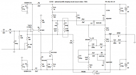
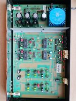
BA builds several very high-end audio products. Their flagship product is the Model 3050, 1500W Mono Block amplifier. This is a work of art as much as it is an amplifier. Craftsmanship is outstanding and superbly executed. Some of the physical specs;

o 22.6" wide
o 13.4" high
o 34.7" deep
o 450 lbs each
o solid granite base, 75 lbs
o current price: $205K dollars

Full specs can be found here.

As we arrived at BA - in a typical business/manufacturing park in Louisville, CO we were met in the small lobby (very understated), by a very nice, energetic, and well-spoken young man named Kenzo. I'd say around 30ish yrs old, and he ended up being a most knowledgeable and gracious host. We exchanged names and he told us a bit about BA. He told us we'd see all aspects of the manufacturing process, and pictures were welcome. We armed our smartphones!

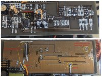
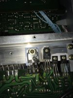
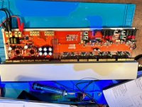
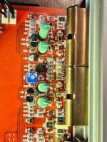
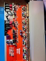
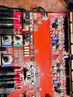
He walked us through, the entirety of their manufacturing process, starting with the milling machines. These are used with raw billets of aluminum (various sizes), which are milled to the specification of each part. One machine was running and milling a small aluminum part used in their proprietary gain stage. He showed us rooms with both raw billets and freshly milled small parts where fine hand sanding is done, and parts stored. Many internal parts of their amps are milled from aluminum as well (think internal resistor supports). Even the remotes are milled in-house. We moved on to a much larger(I don't want to call it a room, as much as a space). This was cylindrical in shape with one end sealed, and the other with a door. It was around 8-10ft in diameter, and roughly 14ft long. This was where the glass-sanding (bead-blasting) was done, by hand, to the massive side heat sinks, and top and bottoms of the amps. Glass beads are used to deliver a more uniform and evenly smooth finish. They farm out the anodizing process to another firm in the Denver area.

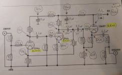
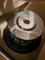
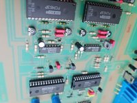
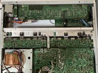
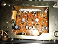
He moved us along and showed us soldering stations where thru-hole (and some SMD) parts are soldered to various PCBs. He also showed us the electronic parts inventory area, where they keep parts on hand for amps and other device that date back 25 or more years. We then moved on see how the massive toroidal power transformers are cased in black epoxy/resin substance that hardens and keeps the humming and vibrations down. No surprise their largest amp the 3050, uses 4 of these massive transformers in one cylindrical tube. Kenzo was not sure of the weight of the raw transformer, but he let me hold one and I'd say, easily 20-25lbs each. The 3050 outputs 1500W/channel! Of pure Class A amplification. All sub-modules and assemblies are tested individually before hand assembly is done.

Kenzo then showed us their pick-n-place machine for stuffing SMD parts and the 'largish' soldering machine. PCBs are not fabbed at their facility, but are made in the US. He also showed us their warehouse and shipping area, where the very heavy components are boxed and crated for shipping to their dealerships. Other, less weighty items are double-boxed with uber-thick cardboard for safe shipping. As we were walking to the listening room, we got to meet and speak briefly with the owner/CEO of BA, Jeff Nelson. More about Jeff and the BA story can be found on the internet and YouTube.

Now for the most exciting part of our tour....

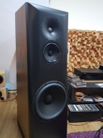
The last part of the tour, and probably the most anticipated, was getting to hear what the BA gear could dish out - specifically, the 3050 mono block amplifiers, each attached to the gorgeous Focal Grande Utopia EMs. And DISH OUT they did! The equipment used in their demo room that we listened to consisted of; their model 812 DAC/Streamer/Preamp feeding their 3010 Preamplifier with separate Power supply, feeding the 3050 mono block amps and each feeding the enormously large, Focal Grande Utopia EM in red. Just for some idea just how large these speakers are.. they stand 80" tall, 26" wide and 35" deep. Oh, and by the way, weigh in at 584 lbs each!

The listening room was about roughly 20' wide x 30' deep. Kenzo provided the exact dimensions, but I can't recall the details. The only treatments in the room were large roughly 9 x 10' cloth covered shallow panels in the middle of each wall. They took a very conservative approach with treating the room, so nothing fancy.

The moment of truth was about to be revealed as Kenzo took out his phone and fired up the first track using Roon. I believe the track was all instrumental without vocals, but can't recall the specific details. All I can remember was how it sounded. The absolutely smoothest, effortless music that has come out of any system I've heard. The precision and articulation of each and every note could not have been better. My son and I were equally amazed with the sound we were hearing. The pure sonic expression of music, as if you were seated in the middle seat of the studio, or stage. And the noise floor? Well, it simply wasn't there.

Next up was a very unique piece by Yosi Horikawa, entitled 'Bubbles'. However this piece was recorded in 2 dimensions, it sounded like bubbles bouncing and popping from wall to wall. The soundstage simply jumped off the stage, so to speak, and widened from wall to wall. You clearly heard sound outside the physical side boundaries of the speakers themselves. Impressive. 3D sound from a 2-channel. Awesome.

Kenzo handed the phone to my son and he queued the track, 'Give Life Back to Music', by Daft Punk. This track is a favorite of his and really sounded over the top with this system. Once again, the details and dynamics were so crisp and distinct. The way music should be heard and enjoyed. Next in the queue was familiar to everyone, 'Landslide', by Fleetwood Mac. This track was impressive as well, The guitar work was outstanding and the soundstage was telling. Every note plucked was clear and distinct. While not as dynamic per se, it was very well rendered on this system.

Next, I queued up a favorite of mine that I use as a reference, goto track when I audition anything I've built(or bought) - whether an amp, pre, or DAC//streamer remote for Roon. It is one of the most well-done recording in my library, short of some noted DSD tracks from Michael Jackson's Thriller album. The track is 'Walk My Way', by Beth Nielsen Chapman, from her self-titled album. This song has a lot of dynamics, done with a lot of staccato (quick end) to the notes, each note was precisely executed and positioned on the soundstage. The stereo separation was obvious, but well-balanced. At the volume we were listening at, this track brought a big smile to my face, noting how well it was reproduced, confirming my own ears when I tagged it years ago as a demo track. Even Kenzo made a note to save it in his favorites for other occasions. Oh, did I say the system we were listening to came from $410K worth of amps, and $280k worth of speakers! Not to mention their preamplifier that adds another $233K!

There had to be a end to our listening fun. I sat there in awe saying to Kenzo, that this system, "was the cleanest sounding systems I had ever heard." As well it should be. It ticked every box for what an audio system should sound like. Yeah, no kidding! At this price point, who wouldn't want to listen to it. I know one thing, my current system has a lot to aspire to! A well designed, engineered, executed and delivered - price no object - will richly reward you with the best sound your ears have ever heard.

Sadly, we had to leave, but Kenzo mentioned, that anytime I was in the area he would arrange a weekend session. I gladly accepted.

Ps. Nay sayers will baulk at the price of the system described here, and say, 'what average audio enthusiast can afford something like this'? Very few, and I would agree. But, that doesn't mean we can't afford ourselves, the opportunity when given the chance to experience the big, bold pure music that pours out of these speakers like a crystal clear Rocky Mountain stream, backed only by exacting electronics, and in the end 1500W of Pure Class A amplification through two of the well-regarded, Focal Grande Utopia EM speakers. For us, it was quick side journey to the mountain top, if only for a moment in time, to listen to sound approaching sonic nirvana.

If you ever find yourself in the Denver, contact Boulder Amplifiers and arrange a tour of their facility. I guarantee you will not regret it, and it will be of those times you think back on it with a big smile on your face.

More on Boulder Amplifiers here.

Rick

Boulder-Amplifiers-Entry-Rock-Sign-650x365.jpgPXL_20230913_185732783.jpgPXL_20230913_191115763.jpgPXL_20230913_191212684.jpgPXL_20230913_191224099.jpgPXL_20230913_191616983.jpgPXL_20230913_192419803.jpgPXL_20230913_192507126.jpgPXL_20230913_193042199.jpgPXL_20230913_193334650.jpgPXL_20230913_193538290.jpgPXL_20230913_193645390.jpgPXL_20230913_193727333.jpgPXL_20230913_193857415.MP.jpgPXL_20230913_195100357.jpgPXL_20230913_195110456.jpgPXL_20230913_195135974.jpgPXL_20230913_195519319.jpgPXL_20230913_195553697.jpgPXL_20230913_200849171.jpg
  • Like
Reactions: Bonsai and 6sX7

Free stuff, pickup in ashland, MA

Gone!

Pickup my older projects. All or nothing, some gems for the handy diyer. Make it easy for me, not a lot of questions or splitting things up, hoping to have them gone asap.

Jbl 2430h compression drivers pair. Rough shape but pass sound, aluminum phragms seem okay though, at least one core is out of spec. These were badly stored pulls from an evoi system, not the current gen stuff.

Lite dac-ah cases. 6x8.5, with nice rcore trafos. One replacement board, but probably only good for cases, conns, trafo.

Transcendant OTL-SE. may only need a retube, some hackish psu mods but the audio cct, iron etc is sll original. I have some of the tubes but others were damaged.

JBL 2404h-1 pair
Some cosmetic issues but I think they’re on-spec.

B&K 667 tube tester. Think it just “needs” an axial fuse but I have enough projects.

2x hypex smps600 v3. I think they just need new relays.

Audiosource amp a100.

Pots need a cleaning and the auto-on cct is obnoxious. Good bench amp.

That’s it! You get a load of parts at worst, I get some space. Ideally today!!

Attachments

  • IMG_1978.jpeg
    IMG_1978.jpeg
    612.1 KB · Views: 92
Projects by fanatics, for fanatics
Get answers and advice for everyone wanting to learn the art of audio.
Join the Community
507,801
Members
7,889,012
Messages

Filter

Forum Statistics

Threads
406,269
Messages
7,889,012
Members
507,801
Latest member
TMCK001