Dear diyers
Yes, I'm building an Aleph 30 for me, despite it's an old Mr. Pass design. I love it.
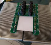
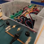
I've already soldered the main parts. Lucky me, I could find two big alluminium heatsinks from two decommissioned 1 kW radio transmitters, so two sides of the enclosure are done. The other sides will be alluminium plates.
My question:
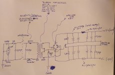
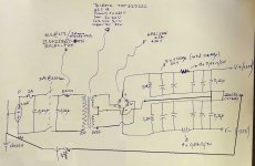
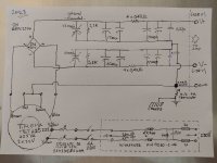
I'm attaching the power supply scheme to see if everything is in order. I followed almost the original Mr. Pass design, but the transformer and the thermistors are european (german transformer and Epcos thermistors) so I would like to know if anyone envisages potential problems, before making the complete PS (by now I only soldered the capacitors, the CRC part).
Additional comment:
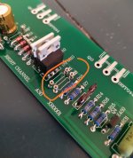
Despite I was able to match the input mosfets (IRF9610) to 3.707 V (exact match for both in rigth channel) and 3.699 + 3.700 (for the left channel) using 12Vdc and 1.5kOhm resistor, I put some receptacles in R8 position (just in case).
If anyone is interested, Digikey part 9900-0-15-80-22-27-04-0 will fit for purpose for any 1/4 watt resistor.
Acknowledgement:
I was able to do the diy work I did only because I found information and learned a lot on this site, so thanks to all.
It will take some time to finish the alluminium (enclosure) works. I hope will be able to share some pictures then.
Thanks
Yes, I'm building an Aleph 30 for me, despite it's an old Mr. Pass design. I love it.
I've already soldered the main parts. Lucky me, I could find two big alluminium heatsinks from two decommissioned 1 kW radio transmitters, so two sides of the enclosure are done. The other sides will be alluminium plates.
My question:
I'm attaching the power supply scheme to see if everything is in order. I followed almost the original Mr. Pass design, but the transformer and the thermistors are european (german transformer and Epcos thermistors) so I would like to know if anyone envisages potential problems, before making the complete PS (by now I only soldered the capacitors, the CRC part).
Additional comment:
Despite I was able to match the input mosfets (IRF9610) to 3.707 V (exact match for both in rigth channel) and 3.699 + 3.700 (for the left channel) using 12Vdc and 1.5kOhm resistor, I put some receptacles in R8 position (just in case).
If anyone is interested, Digikey part 9900-0-15-80-22-27-04-0 will fit for purpose for any 1/4 watt resistor.
Acknowledgement:
I was able to do the diy work I did only because I found information and learned a lot on this site, so thanks to all.
It will take some time to finish the alluminium (enclosure) works. I hope will be able to share some pictures then.
Thanks
It has been a while...
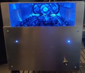
I just want to say that the Aleph 30 construction was successful, and would like to share some photos and some info.
Now I know how it feels to make your first padawan's lightsaber. Thanks to Master Pass for sharing knowledge and fun. Thanks also to Zen Mod for all the posted stuff. It has been very valuable. Thanks.
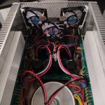
Except for the PCBs, the amplifier and the enclosure are self built, mostly with recycled aluminium and a simple Dremel tool. As said before, the main heathsinks came from decommissioned GSM cell 1kW amplifiers and bought as aluminum scrap.
I matched the IRFP244 power mosfets in 4 triplets with 0.002-0.001 voltage tolerance, following Master Pass suggestions for measurement, but I used 12V with 40 Ohm resistor and a heathsink for 2 minutes until Vgs stabilize (triplets joined like this: one triplet at 3.946 Vgs; other at 3.954 Vgs; and finally 3.960 and 3.974. 12 Mosfets selected from a bunch of 22 Vishay IRFP244 PBF that were very close, maybe because are of the same manufacturing batch???)
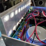
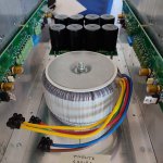
Because of using a Talema 625 VA transformer with secondary at 2x22 V, I put two thermistors (phase and neutral) to lower a little bit more the voltage and got +/-28 V DC in the rails. After hours drops to +/-27.8 V
Bias measurement gives to me 2.23 Amps, so this guy gets really hot. First cooking measurements gave me 67.1 Celsius degrees after 2 hours barbecue.
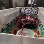
For that reason I decided to buy some 12 V pc fans (low noise and expected 100.000 hours lifespan...!!!, maybe it's not true but I liked the specs) and to put additional heathsink inside (why inside?) to make the fans to blow the heathsinks and put out some hot air.
The final result is that I'm getting maximum 26 Celsius above environment temp. Fortunately the fans noise is really difficult to hear with the amp two or more meters away. By the way, this constrained me to put inside an additional little and cheap switching 12V PS for the fans.
A little hum from the mains (and ripple I guess) is audible if you are very close to the speakers. DC offset is some mysterious thing, on switching on the amp it's " high" (I mean " high" something between 20 and 40 mV) but afterwards it seems to stabilize around 4 mV to 12 mV. When disconnecting the amp it gets high again while the PS caps "de-energize". I have to conduct more measurements, but I honestly prefer enjoy listening to music than continue to worrying and measuring things in a masochistic way. Music is terrific. Dynamics and details are awesome.
Dimensions: 25 cm width, 23.5 cm tall and 38 cm deep. 15 kg of a beast.
(About the source: I bought a very old and malfunctioning CD player for a few bucks only to desolder and extract the TDA1541A inside. Then I bought a JLSounds i2s to USB board v.3 and built a NOS DAC using the TDA1541A in simultaneous mode. chip analog output set at 0 Volts point, with I/V conversion trough 33 Ohm special non inductive resistors and a classic single couple FET-MOSFET preamp at 18Vdc. The result is stunning...!!!)
(About the speakers, this is a very long story, they were designed by me with VituixCad help, a Behringer calibrated mic and some free software like LIMP. It has been a long and very fruitful journey...)
Thanks again
I just want to say that the Aleph 30 construction was successful, and would like to share some photos and some info.
Now I know how it feels to make your first padawan's lightsaber. Thanks to Master Pass for sharing knowledge and fun. Thanks also to Zen Mod for all the posted stuff. It has been very valuable. Thanks.
Except for the PCBs, the amplifier and the enclosure are self built, mostly with recycled aluminium and a simple Dremel tool. As said before, the main heathsinks came from decommissioned GSM cell 1kW amplifiers and bought as aluminum scrap.
I matched the IRFP244 power mosfets in 4 triplets with 0.002-0.001 voltage tolerance, following Master Pass suggestions for measurement, but I used 12V with 40 Ohm resistor and a heathsink for 2 minutes until Vgs stabilize (triplets joined like this: one triplet at 3.946 Vgs; other at 3.954 Vgs; and finally 3.960 and 3.974. 12 Mosfets selected from a bunch of 22 Vishay IRFP244 PBF that were very close, maybe because are of the same manufacturing batch???)
Because of using a Talema 625 VA transformer with secondary at 2x22 V, I put two thermistors (phase and neutral) to lower a little bit more the voltage and got +/-28 V DC in the rails. After hours drops to +/-27.8 V
Bias measurement gives to me 2.23 Amps, so this guy gets really hot. First cooking measurements gave me 67.1 Celsius degrees after 2 hours barbecue.
For that reason I decided to buy some 12 V pc fans (low noise and expected 100.000 hours lifespan...!!!, maybe it's not true but I liked the specs) and to put additional heathsink inside (why inside?) to make the fans to blow the heathsinks and put out some hot air.
The final result is that I'm getting maximum 26 Celsius above environment temp. Fortunately the fans noise is really difficult to hear with the amp two or more meters away. By the way, this constrained me to put inside an additional little and cheap switching 12V PS for the fans.
A little hum from the mains (and ripple I guess) is audible if you are very close to the speakers. DC offset is some mysterious thing, on switching on the amp it's " high" (I mean " high" something between 20 and 40 mV) but afterwards it seems to stabilize around 4 mV to 12 mV. When disconnecting the amp it gets high again while the PS caps "de-energize". I have to conduct more measurements, but I honestly prefer enjoy listening to music than continue to worrying and measuring things in a masochistic way. Music is terrific. Dynamics and details are awesome.
Dimensions: 25 cm width, 23.5 cm tall and 38 cm deep. 15 kg of a beast.
(About the source: I bought a very old and malfunctioning CD player for a few bucks only to desolder and extract the TDA1541A inside. Then I bought a JLSounds i2s to USB board v.3 and built a NOS DAC using the TDA1541A in simultaneous mode. chip analog output set at 0 Volts point, with I/V conversion trough 33 Ohm special non inductive resistors and a classic single couple FET-MOSFET preamp at 18Vdc. The result is stunning...!!!)
(About the speakers, this is a very long story, they were designed by me with VituixCad help, a Behringer calibrated mic and some free software like LIMP. It has been a long and very fruitful journey...)
Thanks again
Attachments
Last edited:

The original purpose of the post was related to the power supply. Sorry, I forgot to say that I obviously followed what suggested by Zen Mod (you have always to hear what the seasoned padawans say).
Initially I was thinking on adding massive capacitance, but finally the dimensions available constrained me to a simple CRC with the same original capacitance as the Aleph 30 was designed, but with a single PS for both channels. Te PCB is easily available from China (as always).
I put two 4 amp fast fuses inside the mains receptacle because it was what I had at home, but will try with 3-2 amp slow fuses some day...I guess... as the inrush current shall be not that enormous thing using two thermistors.
A sketch attached (a very simple and fast hand made sketch, sorry for that).
Attachments

A question.
I've been running the self built Aleph 30 for several days and hours. In fact I'm listening music while writing this post.
I have to say that I'm very happy and pleased with the sound.
More or less after an hour the initial hum reduces to something insignificant and the music is more detailed, clean and transparent. Nevertheless I've been thinking on throwing away a volt from the +/- 28V supply because of the temperature and to further reduce the mains hum and overall mains noise, but honestly don't know if this makes sense, so would like to know what other more experienced diyers thinks about.
My idea is to take away the four 0,47 Ohm resistors in parallel inside the CRC and to replace them with a single hand wounded coil of about 0,25 Ohm resistance (the resulting inductance could be whatever, because should be very low anyway) made with copper wire 0,71 mm diameter. Should be something near 6 meters of wounded wire. I already have the wire at home (old remaining stuff).
Is this a worth modification? maybe better to change only the single resistors to a higher value like 1 Ohm? the difference will be very very small so better to leave as it is?
What do you think?
Thanks
- Home
- Amplifiers
- Pass Labs
- Aleph 30 PS advice