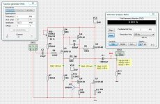
I have this circuit working well in SIM, I ordered PCB for it to build the real one. How can I reduce the feedback or improve the feedback circuit? ALso, i'm told that top and bottom should hare the same amount of dissipation?
I'm open to ideas and suggestions as is my first homebrew.

I'm open to ideas and suggestions as is my first homebrew.
Last edited:
Show your circuit better without all those multimeters.
Like it shows now it is impossible to see.
Then you will get help.
Stefan
Like it shows now it is impossible to see.
Then you will get help.
Stefan
Last edited:
What do you mean by 'improve the feedback'?
You want more or less feedback?
Who told you about that dissipation thing, what was the rationale behind that?
Jan
You want more or less feedback?
Who told you about that dissipation thing, what was the rationale behind that?
Jan
Hello, Jan and Lineup. Thanks for stopping by. As you can see I am applying a lot of feedback to stabilize the circuit. I would like to find a way to isolate AC/DC feedback and reduce AC feedback or make it variable. I have a retired professor helping me and he was trying to figure out the way to balance each half; so they each carry half the load. I have made a clearer drawing for Lineup:

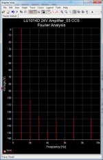
What does Fourier analysis show?
Is it mainly 2nd harmonic?
What is voltage DC at output point?
Is it mainly 2nd harmonic?
What is voltage DC at output point?
Last edited:
I have setup your way of using LU1014D.
It really works well.
But I have changed it to improve.
There is no need for parallell two LU1014D.
My test shows max output is round 6 Watt.
When the output DC voltage is set like 14.0 Volt.
I replaced a resistor with a current source 10mA.
THD is now 0.0007%

It really works well.
But I have changed it to improve.
There is no need for parallell two LU1014D.
My test shows max output is round 6 Watt.
When the output DC voltage is set like 14.0 Volt.
I replaced a resistor with a current source 10mA.
THD is now 0.0007%
That looks very nice lineup, i am tempted to try it. You know i got lu1014d. I can send some your way if you promise to build it. Let me know.I have setup your way of using LU1014D.
It really works well.
But I have changed it to improve.
There is no need for parallell two LU1014D.
My test shows max output is round 6 Watt.
When the output DC voltage is set like 14.0 Volt.
I replaced a resistor with a current source 10mA.
THD is now 0.0007%
View attachment 1193699
can you send me the source project file for it. I would like to make PCB, I also want to provision real estate for parallel output devices as there is some performance and DC OP stability improvements doing so that do not show up easily in Spice. Papa spoke about it briefly (aside from current sharing) in his PLH paper and there is no harm done in allocating extra space on the PCB for parallel operation of matched LUs.I have setup your way of using LU1014D.
It really works well.
But I have changed it to improve.
There is no need for parallell two LU1014D.
My test shows max output is round 6 Watt.
When the output DC voltage is set like 14.0 Volt.
I replaced a resistor with a current source 10mA.
THD is now 0.0007%
View attachment 1193699
Last edited:
I use Multisim 12.
I can not use .ms14 files. I do not think you can use .ms12 files.
But you can try.
I have added a potentiometer to set the output to 14.0 V.
What should be added is a noise/ripple filter for the input.
One resistor and capacitor from the supply.
I can not use .ms14 files. I do not think you can use .ms12 files.
But you can try.
I have added a potentiometer to set the output to 14.0 V.
What should be added is a noise/ripple filter for the input.
One resistor and capacitor from the supply.
Attachments
Last edited:
May need to check the LU for gate leak @ Vds >~ 3V & elevated temperature, at least for the lower FET. Could easily end up in flames otherwise.
Could you modify it according to my real test of LU1014D, so it could work?I use Multisim 12.
I can not use .ms14 files. I do not think you can use .ms12 files.
But you can try.
I have added a potentiometer to set the output to 14.0 V.
What should be added is a noise/ripple filter for the input.
One resistor and capacitor from the supply.
This is model Lu1014D in your file.
Below is real:
As you can see It is not practical operational over 10V VDS at all.
I tested your multisim file, both Lu elements are operating outside the operational zone.
Could make it swing 0.5-4.5V VDS? -0.7~-1.3VGS, from unattenuated input signal?
How much output Vpp will be?
PS: How to make a more realistic model file for Lu1014D?
- Home
- Amplifiers
- Solid State
- Need help to optimize my LU1014 SRPP amp

