NTC Thermister and light bulb current limiter issues?

has anybody had an issue with using a light bulb in series for current limiting on an amp that has a NTC thermister in series with the incoming AC power.

I have a 200W linear bass amp, in an Ampeg BA115HP. It had a shorted opamp that I was trying to isolate, and though I could leave the preamp board disconnected to see which opamp was causing the short. But my 16V zener diodes were on that board, so my +/-16V went to +/- 50V. ooops!

So i replaced the mains FET transistors, and decided to use the light bulb limiter. But as I ramp up the AC voltage the light bulb gets bright, at around 30 vac and gets getting brighter. My +/-50V buses are clamped at +/-4V as if by design?

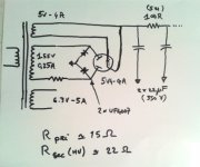
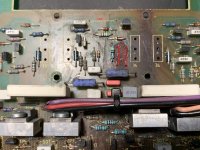
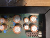
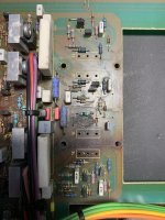
I can't find anything wrong. The output from the transformer is good with no load. But i noticed a big black NTC in series to limit the in rush current. Probably a good idea since the 1st filter caps are 5600uF each.

But I noticed the NTC thermister isn't getting hot. Just slightly warm. In that state it still has a 5K resistance, so perhaps it is limiting my voltage?

I am going to try and take it out of the circuit, but I don't expect it to matter.

Any ideas on what else to try? I have almost no voltage across the 0.33 ohm resistors in series with the main power transistors, so I don't think my amp is causing the high current draw.

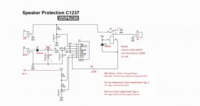
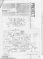
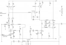
Here is the schematic.

115b by Dennis Kelley, on Flickr

115a by Dennis Kelley, on Flickr

How to wire one-per-string magnetic pick-ups

Hi, I have built a five string electric upright bass and bought the magnetic pickups used in NS basses. I have a Bartolini preamp to buffer and mix the signal from these and a piezo installed on the bridge.
Three pick-ups are labeled positive, two are negative and one is a null. Here is the description from the seller's site:

The EMG 5SW is a magnetic pickup system designed for Electric Upright Bass. The system was initially designed for Ned Steinberger and is used on NS CR and EU instruments. Price is per set of 6 pieces, made by EMG, cables with in-built connectors, set made of 3 pcs of positive pickup, 2 pcs of negative pickup, 1 pc of null pickup

Should I wire them in series like this:
POS-NEG-POS-NEG-POS-NULL ?

Attachments

  • 0001275_480_emg-5sw-magnetic-pickup-set.jpeg
    0001275_480_emg-5sw-magnetic-pickup-set.jpeg
    37.6 KB · Views: 410

Yamaha RX-700: loud pop from the left speaker during shutdown

FIXED: Yamaha RX-700: loud pop from the left speaker during shutdown

Hello all,

I have Yamaha RX-700 amplifier from the eighties. The device has a common "soft start / shutdown system" that should prevent pops from the speakers during startup and shutdown. For an unknown reason this feature is not working properly anymore during shutdown: when the relay cuts power from the speakers, a loud pop (or more like a bang) is heard from the left speaker (and left headphone speaker). Turning volume knob to zero before shutdown does not help.

I called to a repair guy but he was not even interested to look the device because he claims there's too many possible causes to this phenomenom so it would probably be costly and therefore not recommended.

I'm quite a noob in electronics so I have no clue what to do. Nonetheless I measured the left channel speaker output terminal several times with multimeter and got something like +2V spike. However, my meter resolution is only 3 samples per second so I probably didn't get max value.

I also measured some voltages from the PCB and noticed that just when the relay cuts power from the speakers, the voltage jumps suddenly from 0 to 52-53 volts on both channels and then starts to fade back to 0V. Is this normal?

I also tried to measure the power supply voltages. From the middle pin I got 65 VAC although this goes directly to the "ground" or "neutral" collector on the PCB. Is this normal? Other pins give me 90VAC and 40VAC.

If I shutdown the device from the main power switch, there's no bang from the speaker even though the shutdown sequence should be the same: first the power-switch-relay cuts power from the protection circuit, then the speaker relay cuts power from the speakers. Or that is what I think is happening.

The simplest fix to this issue would be to press the "speaker select button" to deactivate the speakers and then shutdown the device but I don't like that.

Any ideas what to do?

The Ultimate Analogue Test LP AAPT-1 vs HFN 001

I used my Analogue Productions test LP to set up my new mc cartridge. This is the first use of this test LP for me. I have used the HiFi News Test Record 001 since 1996. It is used sparingly and is in pristine condition. I noticed that the pink noise tracks 2, 3 on side 2 of the AAPT-1 is very much lighter in the bass (below say 500 Hz). I would estimate about 4 dB down. This is consistent with all my carts and phono stages. Has anyone else noticed this? My speakers are 3-way active and are set up to be flat on the pink noise track of the Test CD HFN 020. So, the HFN pink noise test tracks on LP and CD are in good agreement but the AP pink noise shows a bass shelf down. Any opinions on why this is so?

Rockville Bluetube Integrated amp $179

Hey just saw eBay promoting this tube bluetooth and analog integrated amplifier.

Wondering what you think?

Price is $150w/ free shipping in USA? (note- not $179 (sorry about the title of this thread) but $150)
Regular price is $300, so its "on sale"

Yes I assume its cheap and from china, but it actually looks pretty neat.
Link-
392187141147 | eBay

An externally hosted image should be here but it was not working when we last tested it.


Note- not affiliated in any way with this stuff!

I am wondering if the tubes are for show or actually hooked up, and whether there are actually 3 transformers under that big back section, or if its a tiny chipamp or class D dealie.

But $150....its almost worth a look.....

MarkAudio CHR-70 in Woden Lotus

Hey guys,

Just finished up a pair of Lotus double mouth horns loaded with MA CHR-70 drivers. Initial impressions are very good. They still need many hours of break in, so I’m holding judgement for now.

Mainly posting this because I know I had trouble finding good phots of these towers complete (with size references) when I was first considering this build. They are my second build. My main stereo pair(s) are B&W N805s and Zaph ZRT Revelators (first build).

And it’s downright spooky how a pair of ~$40 drivers in large well designed horns can run with “higher end” multiway speakers.

Anyway, just some click bait for you guys I guess. Carry on.

Tanner

5CB97ADB-06B6-4CF0-B3C3-2A117C394CE4.jpg

2A98CD1E-859B-4827-917B-2A2F11BE1FA0.jpg

In need of good class D amp

Hi everyone.

I recently made a boombox and bought sanwu audio TDA7492 2.0 2x50W AMP. Not only I got faulty one (around 5 pops when turning on and 1 after stopping playing music), I also broke it with my 4Ω speakers and 90W power supply and now it heats up to 60°C when idle or working.

So here is my question. I want to buy a new amplifier, but i don't know which to buy. I need 2 channels, something that suits my 90W power supply, lots of gain (the dip switches were awesome for me because i use my kit outdoors sometimes [when on gain I do not care about noise, but indoors would be noticeable]), bluetooth. Budget is ~20$

This will be my second amplifier, so any modifications to the board would be hard for me.

Send help.

Need Help with fixing KRK ROKIT 5 G3

Hi all,

My reference monitor KRK ROKIT 5 G3 died just after the expiration of the warranty and there is no service center in my country. Some suggested that it might be a real costly repair and it's better to buy a new pair of some other brand. It was already a huge investment for my future avocation and I am unable to buy another pair in near future or may be never. I tried to google for the schematic or manual but none really helped. Initially I was able to fix it by googling but the problem was back after some days and now it is unusable.

My questions are the following:

1. Is the power amplifier based on TDA7296? ( I cannot identify the chip by physical inspection due to my poor eyesight)

2. Could anyone please guide me on how to (a) by-pass the limiter circuit and (b) that mute mechanism?

3. Is there a good ready to build 2 way Linkwitz-Riley crossover circuit with PCB layout on our forum ? ( I wish to use that incase I cannot fix the original board of Rokit)

3. Is it possible to obtain a service manual ?

4. If anyone has some earlier servicing experience of these monitor, kindly guide me.

Any help is precious for me.
Kindest regards.

Audio Technix 400.1 strong input signal triggers protection

Audio Technix 400.1 strong input signal triggers protection with or without a load connected to the speaker terminals.

The amp uses a small class D type 8 board in the output section.

The amp plays fine at low gain (below 60 percent) but when I increase it to 75 percent the amp will go into protection within about 10 seconds. Cycling the power to the remote resets the amp.

I tried the amp again with the gain at 50 percent and tried increasing the signal in and the amp behaves the same way as it does with the gain control. It does this regardless of wether or not the amp is driving a load or not. Cycling power to the remote resets the fault.

I haven’t seen this phenomenon before. I have check some of the components on the output driver board and the ones I’ve checked test good ( SMD transistors and diodes) I will have to pull board to investigate it further. Before I do that I wanted to know if there is some components of the main board I need to rule out first, or signal checks I need to do on the ICs on the driver board.

I checked the op amps in the preamp section with my DMM and I didn’t discover any unusual readings. I also check the diodes in the preamp section and the resistors in the audio chain.

The amp uses P channel and N channel FETs in the output.

David

New user. First speaker build. All the usual questions!!

------------PREAMBLE / RAMBLING INTRODUCTION--------------


First post here. Hello, nice to be here. Seems like a good place to be!

This community seems to still be bustling along on old school BB forum whatever-it - and is and doing well. The only other forum I frequent that's doing well on a simple old style forum is very community based and quite the wonderful place which has had me end up many times in the dolomites, Italian alps, French alps, and even a helicopter (followed by an Italian hospital). I'm not expecting snow trips from here, but some noob help would be VERY MUCH appreciated.

That's all intended as quite the compliment, just to be clear. I do love a good old fashioned forum and the ones that still tick along nicely have to have something special in them.


Right ------ ON TO THE ACTUAL POINT OF THE POST! -------------


INTRO AND THE BASICS:
--So I'm making my first speaker. I have all the skills and tools needed, I'm a farmer, I can make anything out of anything (so long as you just need it to last till the end of the season). Point being, construction of almost anything is no problem at all. Hexagonal multi point wangjangling pressure canceling hyperwave cab, with a tapered horn poking out the bottom... I have the tools and the materials. All good. No probs.


THE DRIVER AND MY EXPECTATIONS:
--(see pics)-- I have a coaxial driver (I mean, it's all the rage nowadays after the ls50). It's a Focal 6.5" car audio driver. 165ca, they served me well in a MX5 which is no more. I have the two way with crossover version in my newer car and really quite like them (when I'm parked, not roof down on the motorway) I know what to expect, I'm not looking for perfection, just a speaker I can pair with my next project (A nice little mid/bass type sub) and put in a small bedroom. Enjoy the music, and don't fuss the details. Thankfully Focal provide a whole load of data on the speaker, Thiele/Small parameters and whatnot. I'm unfamiliar with what they mean, despite a week of lurking, googling, and generally hoping to find a calculator which would just tell me what to make and save me from having to use my brain😀


MY NEEDS:
What I lack is the knowledge. It's always the case eh. Traditional noob post right here. I have the driver, the skills, and my expectations are appropriately low for a car driver. Where do I start? I'd assume sealed, but ported perhaps? It'd have to be a front port. Long tapered horn thing? I'm keen to get as much bass as I can out of them (check out the frequency response graph in the pics) so my sub (Which I haven't built yet) can be focussed on lower frequencies. The good stuff. No way I'm sticking them in my good system with the good sub - I need a new sub! Again though, my expectations are appropriate for the driver! See what I get first.


SPECIFIC QUESTIONS:

-- Sealed or ported?

-- If ported, what sort? One thing I haven't got is a nice flared tube, but a slot port would be easy enough if ported is the way to go. Again, it must be be front firing though, they're gonna be close to a wall.

-- (see pics) -- I have a crossover from a previous car audio setup that, well, it's a real crossover not the little block on the coaxials. I'm not sure it's a good idea to mess with what Focal have decided is right though so probably not gonna introduce that potential bag of problems into the mix. But, if any real crossover is better than a little block on car audio coaxials, then so be it.

-- Volume of the enclosure. Try as I might I always seem to be missing one TSP that gets me the internet calculators working. Annoying. It's usually "Actual System Q (Qtc)" and "Resonance Frequency (Fb)". I have no idea how to calculate or find that. I've been messing about on diyaudioandvideo.com and their calculators. but my noob status prevents me from believing anything as I don't know the Qtc or Fb as mentioned.


FINISHING UP THE POST:
I could ramble on about this for ages, donkeys years, and eons. And I've already gone on too long. Basically I have some data, and I want to make the best of what I already have, but need help.

So... Here I am, asking the community that seems to be the place where people learn and experiment and build. Any advice or thoughts would be very very much appreciated.

Attachments

  • P1060942.JPG
    P1060942.JPG
    307.8 KB · Views: 246
  • P1060930.JPG
    P1060930.JPG
    286.2 KB · Views: 244
  • P1060933.JPG
    P1060933.JPG
    133 KB · Views: 264
  • Screen Shot 2020-02-14 at 20.45.07.png
    Screen Shot 2020-02-14 at 20.45.07.png
    49.4 KB · Views: 251
  • Screen Shot 2020-02-14 at 19.17.17.png
    Screen Shot 2020-02-14 at 19.17.17.png
    50.1 KB · Views: 240
  • Screen Shot 2020-02-14 at 19.15.50.png
    Screen Shot 2020-02-14 at 19.15.50.png
    195.3 KB · Views: 88

Old school Stetsom 7kD clipping

I have an old school Stetsom 7kD amp that boots up and draws about 8 amps at idle. This is a beast of an amplifier. It has two separate motherboards, so it’s basically two complete amps in one heat sink.

All of the power supply FETs and output FETs test good in circuit.

When I feed a strong signal into the amplifier it will start to show clipping on the LED with no load attached to the speaker terminals and the current draw on the amp becomes erratic and bounces around from 4 amps to 12 amps and everywhere in between.

Does anybody know what could cause this?

I don’t have a strong enough power supply or test speaker or static loads to handle the power that this amp can produce to drive it into clipping. Is there a way to test the circuit at reduced power or is it ok to keep testing it with no load attached to the speaker terminals.

David

Attachments

  • 3AA535A3-6642-44A5-A3BD-3C3E990F88ED.jpeg
    3AA535A3-6642-44A5-A3BD-3C3E990F88ED.jpeg
    491.1 KB · Views: 116
  • 83963840-A6D6-46C5-B4E3-F787D9B812CE.jpg
    83963840-A6D6-46C5-B4E3-F787D9B812CE.jpg
    1 MB · Views: 96

Moded 2226H + 2451J on XT1464

:cop:
Moderator note: Thread title changed at OP's request.

THIS THREAD CHANGES FROM YUCHI A290 HORN TO AN 18SOUND XT1464. FOLLOW Moded 2226H + 2451J on XT1464

Hello again guys. I had a great project going in the fullrange section, a B&W teardrop shape with Fostex 168 drivers. As life has it, something came inbetween. After a long time, wanted to go back to the project and finaly finish it.... When I pulled the enclosures out of a dry storage, they have been badly cracked. That was the second time when translam didnt work (wesayso had same problem). And in the bin they went, sadly.

Now.....new project 😀 Currently Im having a CAD program done for the famous Yuichi A290 horn, so that it can be machined on a CNC router. Found a guy in my country *central Europe) who would be willing to make them. You can find them on ebay and such, but still over 1.000 dollars for a pair. I wanna push the price way way lower. Once I got the CAD file, I will bargain with the CNC company to have them made. As a compensation for good price, I would like to know if anyone else would be interested in a pair. I do not promise this, but I think we could get it down to 600 per pair...depends on the amount of horns he will make.

Danny

How I adapted a speaker protection board to my amplifier power supply

How I adapted a speaker protection board to my amplifier power supply.

I must admit that I'm a newbie to DIY audio. I know the basics of electronics, but I'm not able to make a design myself. I found a lot of helpful posts in the forums of DIYaudio, so I thought maybe I could do something in return. That's why I wrote this post.

Inspired by a lot of articles I read about the "gainclone", I decided to build a set of 2 LM3886 mono power amplifiers. In these articles I also read about the importance of a speaker protection board. As I bought the LM3886 kits from Chinese resellers, I also looked there for a speaker protection board that I could use.
I found several, but all of them had a limited power supply range, and neither of them was in the range that I would need, having a 20 VAC transformer, and 29 VDC at the output of the power supply. These kits all used the NEC uPC1237 Protector IC.
After reading the datasheet I found that the initial power supply range for this IC is 25 - 60 VDC.

So, I found a nice looking set of mono speaker protection kits at AnalogMetric. The good thing is that the kit is very well documented at their site, with a schematic, BOM and user manual.
I compared the schematic with the one from the uPC1237 datasheet, and thought that it would be not too difficult to modify it to my needs.

According to the kit documents, it can be used with Supply voltage 35-48V AC or 15-24V DC. So what did they do? AC as well as DC power can be applied to the power input.
If AC is used, the smoothing capacitor C1 will smooth out the ripple after the half-wave rectifier diode and make it a usable VCC, that also supplies power to the relay.
If DC is used, the rectifier and capacitor are still there, but the function is not used.
This input voltage also is provided to pin 4 of the IC. According to the datasheet pin 4 is used to detect the presence of AC power. When AC power goes off, the IC will trigger the relay to open.
If a DC PSU is connected to pin 4, it will take a long time before the PSU capacitors have lost their power, and the relay wouldn't open immediately.

So, I decided to separate VCC from AC, replace R1 and R4 for values that are fit for the applied power and add R6 in the connection to the relay coil to make sure only 24 VDC is supplied to the relay.
Now I apply 20 VAC to the AC input and 29 VDC to the DC input. As you can see in this post and in the pictures it is easy to calculate the value for R1, R4 and R6.

I also read an interesting article at halfgaar.net about Speaker DC protection with relays. They found that when an emergency occurs to the amplifier the relay contacts often melt together i.s.o. breaking the connection to the speaker. By connecting the N.C. contact to ground, the relay lasts longer. This implies that the speaker needs to be connected to the central contact, and the amplifier to the N.O. contact.

So this is what I did:

- Input and output connections to speaker are reversed. N.C. contact (3) is connected to GROUND!!!
I read about it in this article. Connection is made at the back side of the PCB.
Be aware that if you don't reverse input and output, the amplifier output is shorted to GROUND!!!

- VCC is cut loose from AC in. The DC in connection is made at the lower lead of R4. At the back side of the PCB the trace between D1 cathode and D2 cathode, and the trace between D1 cathode and relay pin 1, are cut. The lead from D2 cathode is not cut off, but connected to the relay pin 1 (back side of PCB)

- R6 is inserted between U1 pin 6 and the relay pin 8/D2 anode, at the back side of the PCB. R6 can be adapted to VCC. R6 (ohm) = (VCC - V relay) / I relay.
The trace at PCB front side from U1 pin 6 needs to be cut.

- C1 (smoothing capacitor) is no longer needed, because VCC is separated from AC in.

- VCC current is no longer running from P1 pin 2 so I switched the diodes. The larger diode is now used as flyback diode (D2), and the smaller one in the AC detection line (D1).

- R1 lower lead is isolated and soldered to the C1 + connection.

- I did not use the speaker GND connections of the board, but connected speaker ground and amplifier ground to star ground in the enclosure. The board itself is also grounded to star ground.

Attachments

  • schematic AM.JPG
    schematic AM.JPG
    41.3 KB · Views: 725
  • schematic modified.JPG
    schematic modified.JPG
    83.6 KB · Views: 693
  • PCB front side original.jpg
    PCB front side original.jpg
    545.3 KB · Views: 669
  • PCB back side original.jpg
    PCB back side original.jpg
    561.1 KB · Views: 606
  • PCB modifications at front side.jpg
    PCB modifications at front side.jpg
    592.9 KB · Views: 565
  • PCB modifications at back side.jpg
    PCB modifications at back side.jpg
    593.9 KB · Views: 197
  • Completed board.jpg
    Completed board.jpg
    627.7 KB · Views: 279
  • Components mounted at back side.jpg
    Components mounted at back side.jpg
    520.4 KB · Views: 272
  • Speaker protection mounted.jpg
    Speaker protection mounted.jpg
    504.7 KB · Views: 393

Spice Model for Multi-Way Loudspeakers

I have been using this model which I found on the web somewhere.
It seems to be 3-way 8 ohm nominal.
But now I need 4 ohm, 6 ohm.
I don't think there is a simple way to convert it to 4 or 6 ohm.
Does somebody have a 4 or 6 ohm model willing to share it ?
2-way also welcome ... Thank you ...

* generic speaker simulation (8 ohm)
* as published in Stereophile Magazine.
*
* Donated by Jaime Arbona, converted to subcircuit form

.SUBCKT SPEAKER G $N_0002
R_R29 $N_0002 $N_0001 8
R_R30 $N_0003 $N_0002 5
R_R31 $N_0004 $N_0002 5.6
C_C9 $N_0001 $N_0005 4.7uf
C_C10 $N_0003 G 3.3uf
R_R32 $N_0006 $N_0005 0.5
L_L16 $N_0004 $N_0007 0.5mH
R_R33 $N_0009 $N_0008 100
R_R34 $N_0008 G 39
R_R35 $N_0008 $N_0010 0.6
R_R36 $N_0008 $N_0011 0.9
L_L17 $N_0011 $N_0009 1mH
L_L18 $N_0010 G 10mH
R_R37 $N_0009 $N_0007 0.7
L_L19 $N_0006 G 0.3mH
C_C11 $N_0008 G 500uf
.ENDS

Chinese (Fake) transistor experiment

I have a parts unit NAD 2100 power amp that I recently got going again. My experiment was to install any blown transistors with parts from Aliexpress and ebay and see how it would perform.

These were the parts that were ordered and installed:

two 2SA1302 (Toshiba output tranny)
two 2SC3281 (Toshiba output tranny)
two 2SA1011 (Sanyo)
two 2SC2344 (Sanyo)
several 2SA1370 and 2SC3467 (Sanyo)

The parts arrived after several months of travel from mainland China. The big transistors look very similar, but the connection legs are much cheaper looking and feeling than the genuine parts. The TO-92 package parts are virtually indistinguishable from the real thing.

After installing, I fired up the amp on the DBT and there was no smoke and the relays clicked. Both bias trim pots were set at the absolute minimum and centre voltage check was performed. Initial sound tests were also positive - amp sounded normal, transistors remained pretty cool to the touch.

Here is where the fun began. I decided to turn off the amp and adjust idle current to NAD specifications: 15mvDC (+/- 1mv). Bias adjusted normally, but I noticed that the trim pots were turned quite a bit more clockwise than I remember. I could start to feel heat coming from the A1302s and C3281s. I let it idle for a little while at this bias level and heat remained pretty constant. Turned the amp off, hooked up a pair of speakers and audio to the input jacks. Fired it back up and we had sound. This lasted for approximately 15 seconds before the right channel shut off and resistor R444 burst into flames 😱! Left channel wasn't far behind as resistor R443 was starting to let out the magic smoke, but I shut the amp off before it caught fire too.

So, moral of the story is, these fake transistors will function in a certain capacity, but do not try to bias them. Of course, the true moral is avoid these parts at all cost unless the originals have no substitutes.

Suggestions for a clipping detector for my JLH1969

I would like to fit a simple clipping detector to my power amp.

Each channel has a seperate DC power supply, which is single rail.

I'm looking for a decent, low parts count circuit that i can retrofit easily.

The internet is full of examples, but each circuit I have come across has people saying it is ok, and others saying it doesnt do the job properly ...

A secondary aim is to figure out whether I picked the wrong transformer when I originally built the amp. I know I am on the lower end of what the boards can handle.

VTL ADL DELUXE Valve Pre Amplifier by David Manley

Hello.
For sale a Stereo tube pre amplifier designed by famous David Manley.
One of his first creations upon his arrival to the US.
His work and creations are part of the golden era of HiFi.
It includes phono pre-amp.
The pre amplifier has been revised for speciallist and it is in perfect working condition as well as aesthetic condition (95%).
It belongs to a friend of mine who wants to sell it.
It's perfect condition as I have checked and you can see in pictures
Very high quality component and authentic high fidelity.
Rare product to find for sale.

He is asking 1200€ + Shipping.

Thank you


How to properly remove/reassembly SEAS tweeter grills?

(Sorry if this is on the wrong subforum)

Hi, all! I'm looking for some advice on the safest method to remove the thin metal grill from a SEAS tweeter (specifically, 25TAF/G on a Totem Rainmaker).

I need to remove it because I bought it used and someone has poked the grill inwards, thus making the plastic dot/acoustic lens (which supposedly aids dispersion and frequency response) fall off from the grill.

I wanted to remove it, fix the dent, clean and glue back the plastic dot and then reassembly it.

Any help is appreciated.

Pic of the tweeter in question:

s-l1600.jpg


s-l1600.jpg

Help a newb - Passive I/O box

Howdy DIYers.

Any links/suggestions/orientation or constructive criticism corrections always welcome!

Objective:

Create a passive I/O project box that will serve to split a hot balanced stereo TRS output into Left and Right XLR channels as follows:

Source: RME Headphone DAC output - 75ohm (+13db) stereo TRS (female 6.3mm)

Target: 2x balanced line-level Active speakers/mid-fields.


Preferred Extras:


  • Add a stereo level attenuator (presumably before splitting stereo to L+R)
Luxury Options:

  • An additional (source) input (stereo TRS 6.3mm or 3.5mm), that sums/mults to the same single output pair (honestly, just to patch in my TV line output! I can control the level from the TV)
  • An additional summed to mono output (for re-amping to an amp for a passive Sub-woofer) - happy to build separate re-amper, so can keep this output balanced
I do have an XLR Y-split cable (the original cable that was sold to me on the basis that it contained the necessary resistors in the circuit to prevent the phasey nonsense that prevailed) that I could simply modify (add the in-line resistors and I guess a fuse like bridge to minimise connection pops etc.), not that I have any idea which pins to connect them to nor the appropriate values.


The box just seems like a more enjoyable project and a better overall solution.
Basically just want to use off the shelf components (I don't mind drilling/fabricating the box etc.), but I am not up to customising PCBs etc.


Fire away!


Cheers,
Dylan

Please review my plans to recap Polk Monitor 5s

Hi all.

I obtained my Monitor 5s free a couple of months ago, and they don't sound as good as I'd like, so it's recap time. I've already replaced the external fuses, and that helped big time.

I have no soldering experience, and nowhere near the electronics knowledge that I'd like to have, but this really doesn't look too hard. To practise my soldering skills, I unsoldered tiny resistors and caps in a radio I picked up at the dump, and then soldered them back in. I'm feeling confident about being able to do the larger components that I think I need for this project.

I've read a bunch of posts in this forum, and think I know what I need to do, but I'd really appreciate it if one or more of you would just have a look at my plans and let me know if I'm good to go, or if I need to make changes, or if you think I should choose other parts.

I've attached a pic of the crossover below.

As near as I can tell, I have the following parts.
  • 12uf at 50vac electrolytic capacitor
  • 34uf at 50vac electrolytic capacitor
  • 6.2 ohm resistor at 5w
  • 2.7 ohm resistor at 5w

I plan to replace these with one of the following configurations. One config is considerably more expensive than the other.
Expensive
  • Sonicraft GEN I 12uf Capacitor, from Sonic Craft, 28.46 USD each
  • Sonicap Gen I 34 uF 200VDC, rom Sonic Craft, 62.01 USD each
  • Mills Resistor 6.2 ohm 5 watt MRA-5, from Sonic Craft, 4.60 USD each
  • Vishay Mills Resistor 2.7 ohm 5 watt MRA-5, from Sonic Craft, 3.95 USD each

Sonic Craft shipping 24.12 USD

Total price for two of each component plus shipping to Victoria, B.C., 295.47 CAD!

Cheaper
  • Clarity PX 12uF 250VDC, from Meniscus, 9.40 USD each
  • Jantzen Audio 33uF 400V Crosscap Capacitor, from Parts Express, 13.54 USD each
  • Mills Resistor 6.2 ohm 5 watt MRA-5, from Sonic Craft, 4.60 USD each
  • Vishay Mills Resistor 2.7 ohm 5 watt MRA-5, from Sonic Craft, 3.95 USD each

Meniscus shipping 12.25 USD
Parts Express shipping 31.31 USD
Sonic Craft shipping 14.93 USD
Sonic Craft handling 10.00 USD

Total price for two of each component plus shipping and handling to Victoria, B.C., 174.06 CAD.

I think I'll go the cheaper route, and save myself $125 CAD.

I understand that I should also get replacement standoffs, in case the existing ones don't survive my work. Where do I go to get these?

And, lastly, the existing caps are rated at 50VAC. Replacements are VDC caps. Will that cause me any problems? If "yes", what do I do to deal with those problems?

Thanks,
-Ken

Attachments

  • polk_monitor_5_crossover.jpg
    polk_monitor_5_crossover.jpg
    492.9 KB · Views: 151

Compact 10-12" DIY Sub

Hi everyone, I've been reading a ton about subs lately and have the increasing urge to finally build an active one. At the moment I have some Mackie CR3 speakers on my desk and a Jamo Sub210 8" under my desk hooked up to my PC. The subwoofer really fills the sound out but it doesn't really go far below ~50hz or so.

The room I'm in isn't large at all, 2.2mx3.2m roughly (plus a wardrobe, desk, a couple of PCs etc) which made me think about Hoffmans iron law. I dont need loud plus the room is small, I just need small and low! The Mackies max out at 97dB per pair, I rarely have them over halfway.

I have some experience using WINISD however I'm unsure of what I'm aiming for in terms of response. On the Transfer function mangitude graph, am I supposed to be making the longest flattest line possible with a steeper rolloff or a nice even curve?

I've been looking at the SB Acoustics SB29SWNRX-S75-6. If I go for a 1.75ft^3 (50L) box with a 24hz (4x30 inch port) tuning I get this
An externally hosted image should be here but it was not working when we last tested it.


80W signal results ~103dB output -3dB being at ~23hz, port air velocity just under 16m/s.

I know it's almost pointless asking but how would this compare to the Jamo I already have? It's roughly a ported 12" Cube, 8" driver and boasts -3dB 38-200hz but there is already noticeably lower SPL below 50hz.

Also I keep reading that we don't perceive lower frequency waves as well so how would I work out how many dB I need to keep up with the 97dB Mackies?

I know it's a lot of questions at once so feel free to take a stab at any/all of them and I'm fully open to suggestions.

I'm also aware that this will most likely be an awful return on investment, especially as a first timer. I wouldn't mind spending up to £300ish if it will get me decent results.

EDIT: Not sure why the picture isn't loading up. Uploaded to imgur and inserted using the forum.

Tokin SIT DEFiSIT musings

Having characterized the Tokin SIT for Vgs and transconductance at 24V at 1.5A Ids, I went through my stash of P-channel FETs for a possible match for a DEFiSIT follower.

Parts that I tested are 2SJ162, 2SJ618, IRFP9240. They were all very far away from the Vgs of the Tokin SIT. Interestingly, The 2SJ162 LATFET and the Tokin SIT both have a negative tempco so the Ids falls with temp for the DEFiSIT pair.

I was just about to power down the instruments when I remembered the hockey pucks bought for the F4 beast. Connected the P-channel hockey puck to the curve tracer and BAM! The Vgs of this part is within about 100mV of the Tokin SIT at 24V Vds at 1.5A Ids. The P-Channel puck has a higher Vgs than the Tokin SIT so the pair will have less current than planned.

Quickly lashed up the Tokin SIT to the IXYS hocky puck and POW! Nice steady Ids ~ 710mA after a short warm-up. Increasing voltage rails increases Ids. If you must have 1.5A Ids, just increase the rail voltages.

The IXYS hockey puck that I had on hand and used is the IXTN210P10T. This part at -30V at -2A bias is about 10% of DC SOA and less than 10% of rated max power dissipation.

Looking forward to trying this further when my Tokin SITs show up.

ortofon 2m blue replacement choices

I recently bought a new turntable that came with the Ortofon 2m blue cartridge and I am not digging it. The upper mid range is pushed up and the top end is lopped off. I played about 50 lp's thru it and it's not changing. Yes I have it set up right. Can anyone suggest a replacement for this cartridge that is more neutral in the mids and doesn't lope the top end off for under $300 U.S. ? Thanks in advance.

Alpine MRP-M650 Strange Behavior, Help needed!

Hi Community,

I have an Alpine MRP-M650 that I am trying to repair that has some really strange behavior. With power applied and remote power applied, there is no rail to rail oscillation.

However, when a large signal is applied to the input, the amp comes to life, at high output, obviously, but when turned down, or if the input is completely removed, the rail to rail oscillation remains and the amp operates normally.

There are no output FET damage or any other obviously failed components. All the MOSFET driving signals look good, etc. The output section does run in the low 300 KHz, which is higher than some amps, but I recall from another Alpine that it also ran in the 300s.

I would love to look at the schematic and see where the output clock is generated.

Thanks for input!
Albert

How to calculate fuse values to protect Primary/Secondary windings....please!!

Totally struggling with how to get a start on this!
I'm in the UK (240v) and transformers (toroidal) are 300VA 50-0-50's (in a pair of monoblocks that I'm restoring)

Presently...the only protection is a 3A fuse at the wall plug!

Want to protect both primary/2ndary...and tbh...haven't a clue how to go about deciding on appropriate value of fuses 🙁

I have A-level Physics, (dim and distant past I'm afraid) and can recall my P=IV, and V/I=R...etc...but don't know where to start here.

Have attached PSU circuit diagrams, and hope that someone out there might 'walk me through' the process of calculating fuse values!!??
Perhaps there's some kind of fuse 'calculator' out there that could help??

Many Thanks

Attachments

  • Image005.jpg
    Image005.jpg
    889.5 KB · Views: 774

Corner horns as bass traps?

I have a question for the physicists here. I've wondered this for a while, and once I read a blog which discussed it, but would something like a Klipschorn make a good bass trap, if we replaced the driver with progressively denser sound absorbent materials?

The blog I read didn't say much, except maybe one line that he had two empty folded horns in the opposite corners acting as bass traps.

How would we gauge the efficacy of this without actually doing it? What would the rules be for a bass trap that apply?

Thanks,

Erik

Methods for Reducing Turntable Motor Vibration

I was looking for some idea's on how to reduce the vibration made by an AC Syncronous motor. I have some of my own, but I'm not sure I have a good enough understanding of what causes a motor to vibrate in order to do this.

So, I have read about things like Rega developing a new motor and controller that allowed some adjustments to be made which made the motor vibration completely go away. My assumption is that this was some sort of motor drive that synthesized the drive oscillation and could have the phase tuned in order to minimize vibration, and thats what the adjustment was.

My thorens had such adjustments, and again, vibration could be reduced, though never eliminated by getting those adjustments just so.

I also found that in the case of my new turntable, with a seperate motor bod, that having too much tension on the string causes motor vibration problems.

My motor is controlled currently directly by the wall current, with a transformer used to reduce the voltage from 120 to I believe 12, and I assume that a capacitor is used to "fake" the phase shift. One idea I had was to use an adjustable capacitor to reduce vibration by finding the exact right value. Does that seem like a good or bad idea?

I know that some say reducing the voltage some, and thus torque, can reduce vibration, but at 12 volts, I believe they have already done this enough. However, it may be a motor that works with quite a bit of torque at 12 volts, and so maybe reducing it to 11 or 11.5 would be a way to further reduce it.

Another idea I had was to by a project speed controller and modify its output to 12 volts. It talked about being regulated at 16 volts, so my assumption is that somehow I could reduce the output to 12, if nothing else through resistors. However I believe I could reduce the supply voltage at the regulators to something lower, and that would reduce output. This will still rely on the motor to "fake" the phase shift with a capacitor, but will ensure a perfect 60hz sinewave at a better regulated voltage.

Which DIY board(s)?

Hi guys, DIY amp noob, so please be gentle.

I would like to build a Class D power amp. 2ch, between 100-200wpc into 8ohm.

I'm looking for the best possible sound quality on a budget. Ideally I would like a decent ebay board(s) or are they a waste of time and Id be better of going for Hypex or similar? IRS2092 based?

Any nice kits that come with a credible PSU?

Your recommendations and guidance appreciated.

FS: A pair of Neurochrome Modulus-86 monoblock amplifiers

I have for sale a pair (2) of Neurochrome Modulus-86 monoblock amplifers, precisely installed in two beautiful enclosures. I could say this is one of the nicest and compact built of this amplifier around. For all those who have speakers of at least 86dB sensitivity and looking for a neutral, but natural sounding amplifier, look no further.

Each monoblock consist of 160 VA (230V)transformer, made by my own specifications. Each power supply board consist of 4x10000 uF 50V Nichicon capacitors and dual rectifier fast recovery diodes. For wiring speaker lines, Jantzen solid core wire was used. For indication 2 mm green LED is used on front panel. Mains switch is rated 15A. XLR input connector is gold plated Neutrik version. Dimensions of each monoblock are: 22x27x7 cm (WxDXH). Both monoblock amplifiers are in perfect operating condition.

You can read a lot more information about this nice amplifier here, together with all measurements: Modulus-86: DIY 65W power amplifier achieving -120dB (0.0001%) THD – Neurochrome

Price for monoblock amplifier is 280 EUR + post costs. Payment via PP.

Attachments

  • 001.JPG
    001.JPG
    381.6 KB · Views: 816
  • 014.JPG
    014.JPG
    288 KB · Views: 718
  • 016.JPG
    016.JPG
    484 KB · Views: 705

Active Speakers filters - brainstorm

Hi everybody , this tread it should be place for ideas with a goal to fine tune methodology for measuring active speakers and producing filters as a result.

Wright know it is strange situation on that matter,because nearly all methods used for filters production it is directly imported from speaker manufacturers making speakers with PASSIVE FILTERS and for all kind possible folks with all kind living areas . This what they must do and that is called massive production.
This process looks like this:
1.Producing drivers for speakers measurements done In the anechoic chamber.
This is perfectly OK and acceptable unless will be technology allowing to make driver for your listening space.
2.Producing speakers with hard filters measurements done In the anechoic chamber.
This is perfectly OK and acceptable,because speaker it is for mass production and must to cover needs of anyone.
3. Those speakers arriving to customers room. From this moment on it is whole bunch of speaker measuring methodology principles and software tools ( like Dirac Live )
and other commercial products ( sound traps,diffuses and much more such ) to mach that speaker sound like in In the anechoic chamber.
With that I have a problem . Active speaker system have upper hand to grand fathers technology (passive filters),much more flexibility .


It is two mane schools for making mass production speakers to work for your room and get manufactures achieved result in the anechoic chamber.
First school is - Traditional and use all tools/products mentioned in 3.
Second school is -Modern and can use same tools/products mentioned in 3 but goal is to make any music listening area work with a speaker.
Extreme example is B&O BeoLab 90 speakers, which is expensive and 90% of us mortals never ever will not have any slightest chance those standing in our rooms.


When we (DIY) speaker builders are not targeting to massive production market ,but most of the time but we trying to build best speakers for drivers/room or just speakers concept. Active speakers will have many pros vs passive.
Please don't start discussion about it because is not a point for this thread.

Could be a way start discussion is just describing methodology I'm using at the moment to measure active speakers.

1. Staring point for microphone is at listening position ( have a hard time to justify 1meter or 0,5 meter distance) and sweeps at 75dB ( that should bee to discussion,because filters be targeting 75dB listening volume if you change volume -must change a filter unless it is implemented Equal-loudness contour or fletcher-munson curvein your system) .
Sweeps are done at 0,15,30,45 degrees and averaging all scans in to the one in REW . That is done to the right and left speaker separately and for individual drivers. Results are used for FIR or IIR based.

WTB Vifa M22WR0906 woofers 8" 6ohm or drop-in substitute for Apogee Cepheus spare

WTB Vifa M22WR0906 woofers 8" 6ohm or drop-in substitute for Apogee Cepheus spare

Hi all,
Looking for spares for my Apogee Cepheus 8 speakers to replace aging woofers. Model sought Vifa M22WR0906 woofers.(8"/6ohm) or drop-in replacement if there are any.
Otherwise, is there anyone who can properly re-cone or otherwise repair my existing ones when the time comes?
Thanks for your time.

Icepower 125asx2 based amp

Hi,

I'm in the process of building a pair of Overnight Sensations by Paul Carmody and decided to also make a diy amp (my 1st amplifier). I am waiting for the ice 125asx2 module (made of chinesium... hopefully quality will be acceptable) as Ive read quite a lot of positive stuff about them.

The speakers/amp would be used on a TV attached to Nvidia shield (Spotify/video streaming services).

My current concerns are:

1. Volume control on the amp. Afaik icepower amps need an input buffer to be used with volume pots? So I thought I'd just skip having a volume pot on the amp and just control volume via my TV remote (TV connected to amp via RCA). Is this a good/bad idea?

2. Power button. If I use smth like this: QitinDasen 3Pcs Premium 12V/24V 5A Self-locking Latching Push Button Switch, 16mm Car Ignition Starter Switch, White LED Light Stainless Steel IP67 Waterproof Switch with Socket Plug Wire: Amazon.co.uk: DIY & Tools
Can I attach AC L and N to it, as well as use 24v DC from the ice board to power up the led light? If so, do I need to use a resistor? What resistance?
I would have a fused 220v power inlet at the back.


Thanks!

PCB terminal blocks UL approved for Field-Wiring (FW2)

This may be a little too specific, but I'm hoping that some of you have come across this at some point.

I'm in the process of getting a mains-connected product UL-approved.
The feedback from the UL-engineer is that we must find a terminal block (PCB-mount) that is UL-approved for "field wiring" (code: "FW 2").

The terminal-block we have implemented is only rated for factory wiring (code: "FW 1".

I cannot find any datasheets for relevant parts that even mention FW1 or FW2, but maybe I'm not looking for the right thing?

(The terminal in question is a 5mm pitch screw-terminal rated for 25A/250Vac, but I could get away with a 16A rating)

Kind regards TroelsM

Getting audio signal from IKEA Symfonisk (SONOS)

I would like to get a clean audio signal from my IKEA Symfonisk in order to connect my speakers to my SONOS network. I basically want a $99 SONOS AMP with mono output to ceiling speakers.

I started looking into doing this after seeing this teardown video on Youtube:
YouTube

I found this guide where the author connected a RCA connector to the audio signal from the DAC chip (PCM5101A):

https://www.instructables.com/id/Cheaper-Sonos-Architectural-With-IKEA/

I tried this method and was surprised to hear a superb sound coming out of my speakers, until the system tried to deliver som bass. The sound gets muffled when there is some bass in the the track. I have two theories of why I am not getting a clear audio signal, theory 1 is that it has something to do with the mixing of the two audio channels. As the author states in his guide:

The Symphonisk uses two unbalanced outputs from the DAC. One for the low frequency driver and one for the high/mid driver. We will combine these outputs, relying on the existing resistors to create a passive summing mixer circuit. The software crossover will be adjusted by the Truplay tuning to fix the frequency response to match the new speakers.

My other theory is that when soldering the connector into the circuit, you probably should cut off the rest of circuit from that point on so the Symfonisk PCB doesn't try to use the signal at the same time that the RCA connector is trying to send the same signal to an external amplifier.

My questions that I need some help answering is:

- Should the passive summing work, or are there a better way I can sum the signals?

- Should I try to desolder the resistors on the analog signals coming out of PCM5101A in order to prevent the signal from being shared with the rest of the circuit? Do you think this will make a huge difference?

- Would it be possible to use a device like this and connect to the I2S digital audio bus in order to get an analog signal? audio - How to make PCM5102 DAC work on Raspberry Pi ZeroW? - Raspberry Pi Stack Exchange
Would the external device and Symfonisk circuit be able to decode the I2S signal with a parallel connection to the same bus?

The DAC is this one: http://www.ti.com/lit/ds/symlink/pcm5101a.pdf

Thanks for any help! I will make sure to give back by writing a guide on how to do it if I can make it work!

Marantz cd63ki problem

I have a 63 KI MK2. I know how plagued with laser issues this model is.

Love it. But since day 1 it's been reluctant to play first time when switched on, needing some gentle coaxing in to life, usually after 5 mins or so it will "go". Symptoms are, turn on, put disc in, press play, usually nothing, you can see the drawer move slightly (closed but seems to want to close a little more, but it is properly closed), keep pressing play and eventually it will start to spin the disc up a little, then a little more, then show a disc registry, and finally will spin up properly, show registry and play. Once your at this stage you can play, stop, skip tracks, swap discs as much as you like, till you switch it off and let it cool down, in other words I reckon if you left it switched on 24/7 it would be fine.

I did buy it knowing this and got it a bit cheaper because of it, and the seller who was honest about the fault threw in the new laser mech he had bought but not fitted.

When you put it in service mode it comes up with code 2. laser focus from memory.

I replaced the laser mech yesterday, now nothing, going through the service tests it performs them all, but put a disc in and nothing, will not play now no matter how long you try.

Please Help!

My issue is I love the CD player but really can't afford to get stuck in to a loop of dumping money in to repairing it, if it's something I can track down and repair myself great, but the thought of being in to a repair for £100 or so to pay someone to do it just makes it impractical, while I don't get anywhere near as turned on by a newer cd6006 uk they get amazing reviews, have a usb input and are around £200ish. Dumping too much in to my poor old KI doesn't make sense.

?ITT? dome midrange

I was looking in the window of a local electronics repair shop on the weekend and noticed a whole bunch of solid looking dome midranges. I'd say the size would be more than 2 inches (they show about 2 and a half) and they have a bit of horn loading (about one inch).
I tried trolling the web, but could not find a picture that looked anything like these (sorry, I don't have a digital camera), but they have a square front plate (about 5") with rounded corners and a dedicated rear chamber.
So, I went in and had a look and the only marks on them are:
ITT (in quite large letters)
27 44
49133
60100

None of these helped me in any way. but the speakers were fairly solid - which seems to indicate a fair sized magnet. The only reason I'm hanging off grabbing them is their price of $40AUS - which could be steep (and I don't get paid until next Thursday).
The owner knows no more about them than I do, except that they came from a bankrupt business which he managed to get some 'mint' 70's amplifiers and receivers from, which were still in their original packaging.

Does anyone have any idea what I have stumbled across?

Discrete opamp offset trim

I needed a discrete opamp to replace the one I have in my latest RIAA build so after reading the tech papers regarding the 990 and following the ideas found here: https://www.diyaudio.com/forums/analog-line-level/218373-discrete-opamp-design-173.html#post6071434

I built the following circuit that am now testing as a line level preamp...

Attachments

Firstwatt B2 functionality?

Hi,
I missed the bus on the Firstwatt B2 by many years. Does anyone know of a similar DIY approach for bi-amping using different amps. I’d like to find a preamp/buffer to use with my tube amp and F5-turbo V3 monoblocks driving a pair of LX mini via the analog crossovers.

If anyone has a B2 that they would like to sell, I’d be interested in talking.

How to build a pultec HLF-3C

Hello folks,

Im newbie on this, but want to build my first diy project on HLF-3C filters. I supose its a good newbie project, am I right? I want to make a stereo version, and would like to change some filter values to 20, 30, 40hz on high-pass and 20, 18, 16k on the low pass. Anyone can help me wiyh this? Thanks!

*Not sure If im posting in right place. I know its not a tube project but its part of pultec eqs and i didnt find better place to post. Please move It If necessary. Thanks

Powered sub for ufonken plus?

Two years ago, my son -in-law built a bottlehead sex amp (2 watts) and was looking to build speakers for it.. Dave from planet hi fi, sold me the necessities to build a ufonken plus speaker, which I gave to him last xmas. He had fun building them.

The speakers worked out great and are plenty loud for near field listening (computer speakers). But, as expected, the base is a bit thin. So, I'd like to gather up plans and materials for my son in law to build a powered subwoofer. He has now acquired wood working skills and equipment, so a flat pack is not necessary.

In one of the paid plan sets that came with the ufonken plus, there were drawings for a small cube shaped sub utilizing two silver flute w14 drivers in a push/push configuration. If I remember correctly, Dave thought this might be a good match, utilizing a sub amp, either plate or stand alone. I would like to use a plate amp.

I am thinking of going ahead with this design, but I have questions;

1. Since the plans were not drawn to include space for a plate amp, I am not sure how to best modify the design. I am concerned that if I arbitrarily increase the volume of "the box" to accommodate the plate amp, it might alter the sound. And, If I change the interior volume, would the port need to be resized?

I had thought about compartmentalizing the part holding the plate amp, thereby not altering the original interior dimensions/Sonics of the "box".

2. The drivers come in 4, 8 and 16 ohm configurations. I figured I’d buy two of the 8 ohm variety, wired in parallel for a load of 4 ohms on the amp. Does that sound right?

3. Would a 100 watt plate amp be sufficient?

4. I have seen kits for diy powered subs from places like parts express, which I could consider, I guess.

I would appreciate any feedback or suggestions.

Thanks

Damaged ICEPower 125asx2 board

I'm currently building/assembling a pair of Icepower 125asx2's the cases are aluminium and my speaker binding posts weren't isolated, I didn't realise when testing and damaged the amp as the speakers were all shorted out together. I have now isolated the speaker binding posts but now channel one has horrible noise coming through, hissing popping buzzing, the amp is basically unusable. Any idea what damage I've done and if it's fixable? Thanks

K12G Questions

***UPDATED! K12-G tube amp problem UPDATED!***

***Thread was merged please see the end if you could help. ***

Hello everyone,

I am new here but have referenced here many times for help and browse for the pure enjoyment.

I have the amp listed above and it is about 1 1/2 years old. I am having a problem that I would like some advice on.

Last night I turned the amp on for the first time in about a week. I noticed that the left channel was louder than the right. This has happened before and it was the volume pot. I removed the pot and tried the amp with no volume control...the problem still existed. I then removed the amp from the receiver and used the receiver to drive the speakers. Normally the amp powers the speakers and get it's input from the receiver's preamp output. Using the receiver only the problem went away. I then swapped the left and right channel tubes and the problem moved over to the right channel. Does this sound like a tube problem? What can I do to confirm?

I was frustrated and wanted to make sure I was hearing correctly so I used a low frequency bass track to better hear any differences between the channels. After a few minutes the left channel died. By the way I had switched the tubes back to their original configuration. What happened?

I went to bed and this morning, to my surprise, the was working again on both channels. However, the amp is distorting at a much lower volume than ever before. It isn't that powerful but normally it will drive the speakers more clearly up to a higher volume. Is this tube damage?

For what it is worth I performed most of the modifications here:
S5 Electronics K-12M Tube Amp

I also installed Hammond PT 1609 output transformers.

What do you'll think? Thank you very much.

John

HELP Tubelab sse beginner problem

This is my first amplifier project and it's one of the most cool thing I've ever built. Unfortunately there is no sound from the left channel. All tubes lights up and seems ok in the dark.

Component list:
PT: Hammond 374BX
OT: Hammond 1628SEA
Choke: Hammond 193H
Auxilliary cap: Temco 100 uf
Tubes: 12AT7 Electro Harmonix, Sovtek 5AR4, EL34 Electro Harmonix

I took some voltage measures:
B+: 450 vdc
R17: 32
R27: 33
R10: 0
R20 0

I thought the problem was my potentiometer so I removed it: no change. I've redone all soldering on both side. I took basic triode wiring for my amplifier. D3,D4 TR1 are jumpered. The problem seems in the preamp section... I'm facing a wall, any advice ?

SSE Checkout

Hey All

After about a week of listening to my new SSE amp I figured I would share my checkout and updates on the amp.

First off I am very pleased with the overall sound of the amp and the ease of the build, minus my errors I made while assembling the chassis and selecting some of the components. Best advice I can give is to double check all the values of caps, resistors and your wiring! As many of you know as long as you stick to the build guide George has provided you can have yourself a very nice tube amp.

Right now I am running the amp through a crappy bluetooth adapter as that is all is available to me at the moment. I plan on running this through my turntable with a phono pre yet to be determined.

I am listening to this through Klipsch RB 61 II bookshelf speakers, Klipsch is known for their highs/horns, so you can imagine I have plenty of highs. Only thing that is lacking just a little is the bass but these speakers arent bass beasts so i cant say its the amp. I have played some songs with deep bass and I do get a little kick but thats all these little bookshelf speakers will give me. Id like to audition the amp on different speakers but those are about all I have at the moment, plus I know I am losing sound quality from the bluetooth adapter, bluetooth was really never meant for audio signals.

Currently I am waiting to install my permanent RCA plugs and wire in my real Alps when it arrives and get rid the 100k pho alps I got off Ebay.

I have about 15hrs of listening time in and noticed last night after about an hr of play the amp was getting hot, pretty normal. I usually place a fan blowing across the tubes, excess heat is never a good thing. I noticed my tubes had a nice blue glow as you can see in the picture. Then I noticed my Tung Sol 6L6 on the left was glowing a little red in the plate. Time to take some measurements. I did notice the tip would normally glow a little more red than the next one but figured it was seeing a little more DC.

Here are my measurements as followed in this thread:

Simple SE checkout for dummies

This is what I am running iron wise:

XPWR035 trans, CXSE25-8-5k output transformers and a CXC125-10-200ma chokeR4/150 ohm-

B+ 475/474 VDC
R10/ 220 ohm 2.1 VDC 20mw, 9.5ma
R17/560 ohm 41.5 VDC 3.07 watts, 74ma
R20/220 ohm 2.1 VDC
R27/560 ohm 41.6 VDC 74.2ma 3.09w

Total dissipation R17/27 roughly 32 watts

All measurements taken with tubes in volume all the way open and amp warmed up for 30min

Does all this seem correct? If I am looking at the Data sheets right for the Tung Sol 6l6 I shoud be within range? Leave everything as is or try to put a resister in with R17 to get around 800ohms?

Maybe try some Kt88s, I was reading a thread last night about the unreliability of the 6l6, any input is appreciated!

Attachments

  • IMG_20200207_011840.jpg
    IMG_20200207_011840.jpg
    956 KB · Views: 283
  • IMG_20200207_011253.jpg
    IMG_20200207_011253.jpg
    966.9 KB · Views: 279
  • IMG_20200207_011039.jpg
    IMG_20200207_011039.jpg
    970.6 KB · Views: 278

Yamaha RX-V557 DSP Clock issue

Hi guys!

Been repairing this receiver for a while. The one and only problem so far is DSP. When turned ON (all the logos show well + self check related to DSP is ALL OK) no sound at the outputs, only in Direct mode. Tried reflowing the IC. After that found crystal oscillator XL41 not providing 20MHz, only 100-300Hz ripple.
Imgur: The magic of the Internet
Took off and without it DSP does not pass self check and logos are not working. Placed 25MHz crystal as had by the hand, this freq is OK, but of course DSP still no sound. Today bought exactly 20MHz PTH, soldered and the freq is 2..4kHz of nice sine wave on the one pin and not so fine on the other. Tried 3 of the crystals.
Any ideas of what is going on there? Bad DSP and that's it as No Replacement Part Available according to the SM? Why only for 20 MHz crystal?

How to partially revealed tubes

I am planning my next project, a point to point wired, Pete Millet inspired headphone amp. I would like to construct the amp on an aluminum bottom plate, and leave the sides and top wood.

However, I am trying to wrap my head around how to partially reveal the tubes. An example of the aesthetic I am after is shown in the HiFiMan EF2A Headphone Amplifier or the Bellari VP130.

I think a set of standoffs could raise a tube socket up off the bottom plate, but that seems like it would be hard to wire/assemble. Are there PCB tube sockets with standoffs?

Has anyone tried this before? Any advice? Construction photos?

Thanks for any help.

Example
OD-BI090_TUBES_M_20151020171904.jpg

Hissing sound from speakers, with/without input signal

Hi,
I just picked Sony STR-DA1000ES from Goodwill to use it for my desktop setup.

Everything is good, it sounds awesome, the only problem I am facing with the amplifier is hissing noise.

Hissing noise come when I turn the volume to -30db and up. Otherwise I am not able to hear hissing sound from listening distance. It is there even I don’t connect anything to the input signal, just the speakers.

Its profound at 0db. When I switch to digital input, hissing goes away. Though I haven’t listen any music through digital input, just switched to check if hissing is there.

How can I fix this problem?

Thanks,
Simar

FS: MosFets

Mosfets for sale

IRFP250 All tested, some graded for IDSS matching, 27 total $27.00 SOLD
IRFP9240 All tested, some graded for IDSS matching, 13 total $13.00 SOLD
NTE 2382 sub for MTP8N10, 20 total $20.00
NTE 2383 sub for MTP8P10, 20 total $20.00

Superphon SA120 circuit boards. 5 prs. available. New pair for $5.00

TPO-604N3, hard to find bias Mosfet used in Superphon SA120, $2.00 ea

Wanted 2 matched sets of ECX10N20/ECX10P20...trades for above?

FS: 10 UF Caps

I have for sale a pair of used Jantzen Alumen 10uf caps and a pair of Mundorf Supreme 10uf caps. Asking price is $150 for all four. If you want just the pair of Alumens is $100 for the pair which is basically half the price and $50 for the pair of the Mundorfs. Local pickup is welcome if you in the Western Massachusetts area. Shipping charges additional.
DCC944105609463C88376E95AFDEEC98.jpg

Audiolab 8000A burnt components

Hello. I want to fix an Audiolab 8000A. It's the PCB version 207 016 Issue 3. Some of the components are completely blown. Close to the transistor 2SC2922 (number 36) is the diode 1N4002 but I cannot identify the values of the 2 resistors. Another resistor is blown close to the ZTX transistor heatsink.

I would be very grateful if anyone can help me to identify these resistors.

Also, a picture of the component and track side of the PCB would help me. This 207 is similar, but not equal to other 207s I have seen. It looks this one is a previous version, because the link between TR35 and TR36 was suppressed modifying slightly the position of the components.

Thanks in advance for your help.

Attachments

  • IMG_2011.JPEG
    IMG_2011.JPEG
    721.1 KB · Views: 709
  • IMG_2012.JPEG
    IMG_2012.JPEG
    832.3 KB · Views: 696
  • Model_207_016_3.JPEG
    Model_207_016_3.JPEG
    404.8 KB · Views: 603
  • PCB_5766_18.JPEG
    PCB_5766_18.JPEG
    552.8 KB · Views: 609
  • IMG_2009.JPEG
    IMG_2009.JPEG
    818 KB · Views: 590

Sundown SAZ 1500 - DWM1216FV

Hello, I have an SAZ 1500 in front of me I bought as an experiment to see if I could fix it. I have a little tech background, but this is my first time in a 12v amp. I bought this amp, replaced all the output mosfets, and immediately blew all four 40amp fuses, as well as some of the new mosfets. I removed all the output mosfets, and used a bench supply to turn it on, but the supply would go into protect and not feed any more than 8 volts. While poking around the unit, something labeled DK QK (looks like a transistor?) on the daughter card smoked. I am curious if anyone could explain to me what this card actually is, it's function, and if this burnt transistor could have caused the previous issue as well as its own demise. Should I just replace the DWM1216FV or is there something else that could have cause this and the rest to fail?

Attachments

  • unnamed.jpg
    unnamed.jpg
    1,001.2 KB · Views: 304

Dual layer drywall question

Hey folks, just mudding and taping the first layer of 1/2" sheetrock on my garage walls and i have a question about optimum sound reduction.

First a breakdown of the wall assembly.

Outer wall: original real dimension
2" × 4" with 2" styro board inset flush to 1" barnboard on the outside

Inner wall: floating 2×4 fastened at bottom to foundation and at top to ceiling joists with vibration absorbers separated from outer wall by 1/2" airspace. Inner wall does not actually touch any other outer assembly.
R22 5.5" fiberglass pink filled between both cavities.
6 mil poly vapour barrier tacked on face of inner wall sealed with acoustical sealant and blue tuck tape.
Some joints further sealed with Owens corning JointSealR 4" tape.
All staples sealed with blue tuck tape and bottom of poly sealed to concrete floor w acoustical sealant and JointSealR tape.
2-3 layers of Alcan heavy duty alum foil covering all 6 mil poly.
Bailey RC Plus resilient channel on 24" horizontal centers top to bottom on walls and ceiling fastened at 16" centers on studs with dual layer 1/16" rubber squares and then a 4" x1.5" piece of very sticky Resisto bitumen rubber folded in half and wrapped around the screwing edge of the RC Plus and screwed through to the studs.
1/2" drywall/sheetrock screwed into the RCPlus with 3/4" #6 cabinet screws so as not to pierce the vapour barrier.
All drywall joints sealed with mud and paper tape.

OK, so would it be a better idea to use some drywall mud in small dollops between the first 1/2" sheet and the second 5/8" firecode drywall to help both sheets act as a single mass....
or not and let them vibrate independently.
Which would provide better sound attenuation across the spectrum?, from those in the know.

Suggest a project for this driver

Hi all,

I picked up a JL audio 13w7 in need of a new surround for a song and am wondering what to do with it.

The system in my car is already loud and good enough and so I don’t really want to mess with it.

I also have a fit for purpose home cinema system and so have no particular role for this sub to fill.

This leads me to want to experiment and build something out of the usual sealed and ported box for it.

Given its T/S parameters and with box size being no object (within reason, it has to get through an internal door for example) what would be a cool and fun thing to build with it?

REcOMMENDED cONTINUOUS (RMS) POWER RANGE fOR ONE SUBWOOfER DRIVER:
500W 750W 1000W 1500W 2000W
Amplifier Recommendation: 1000/1v2
13W7-D1.5
free Air Resonance (fs): 23.5 Hz
Electrical “Q” (Qes): 0.476
Mechanical “Q” (Qms): 7.517
Total Speaker “Q” (Qts): 0.448
Equivalent compliance (Vas): 3.68 cu. ft. (104.3 ltrs)
One-Way, Linear Excursion (Xmax)*: 1.25 in. (32 mm)
Thermal Power Handling (Pt): 1500 Watts Continuous
Reference Efficiency (no): 0.269 %
Efficiency (SPL @ 1W/1m): 86.3 dB
Dc Resistance (Re): 2.41Ω
Effective Piston Area (Sd): 107.35 sq. in. (0.0693 sq. m)
Nominal Impedance (Znom): Dual 1.5Ω

Scan-Speak crossover help

I'm a first-time speaker builder, and a few years ago I purchased a pair of D2905/9900 Revelators and a pair of 18W/8545 woofers. I have long-since lost the crossover design I had intended to use. The Reference Monitor

http://www.audiocomponents.nl/speakers/scanspeak/reference/scanspeak-reference_eng.htm

seems to be an ideal speaker design, but it uses a 18W/8546 woofer instead of the 8545.

I'd be interested if anyone could inform me as to what changes to the crossover I would need to implement in order to use the 8545 for this speaker design? The only other speaker I've been able to find on the net using these drivers is at:

http://www.audiocostruzioni.com/a_d...n-revelator.htm

Any other suggestions would be appreciated as well.

Thanx
Projects by fanatics, for fanatics
Get answers and advice for everyone wanting to learn the art of audio.
Join the Community
507,491
Members
7,874,336
Messages

Filter

Forum Statistics

Threads
405,582
Messages
7,874,336
Members
507,491
Latest member
nobodyfamous