SE Output xfmrs....who are the current suppliers for not many $$$

Hi all,

It's been 15 years since I last saw a thread on low priced, or reasonably priced output transformers, the last thread was great but some of the mfrs are gone, part numbers have changed etc.

I have decided to build a single ended tube amp, not sure which output tube yet but I have lots to choose from in stock. Under consideration are 2A3, 211, (242C, 276A, 261A all same size as 211). I would also consider 300B but would have to buy those, I have all the others I listed.

I have been looking around and re-reading the old thread and have found Edcor and Transcendar are still in business, James seems to be gone and some of the others mentioned are getting hard to find. Hammond is still going strong as well and I can get locally as they are a Canadian company.

So what is currently a decent quality SE output xfmr, either Asian or North American? Not looking for specific part numbers, more of a survey of current suppliers. Also don't want to buy the old classic megabuck partridges etc. I see on epay for a kilobuck per pair. Would be nice to find good ones less than $100 ea.

My other thought is to find an inexpensive already built amp with one of the listed tubes, then mod the crap out of it, or gut it and put in my own circuit and use the chassis and xfmrs etc.

Look forward to hearing your recommendations and if you have used them, your opinions of sound quality.

Cheers

24 volt smps conversion to split output +24 / -24 volts

Hi I am building a class-a six channel amp and want to convert a 1000va single output 24volt power supply to split output IE +24v / -24v.
I have searched around and there are a few tutorials for low power applications, but found one on utube which may be suitable for high power. I will be using heftier diodes.
What do you think


YouTube

Sanity check on compression drivers for 811B horns

Hello everyone.

First and foremost I want to say that I have no clue what I am doing, so if I say something stupid, please be patient 😛

I recently acquired some 811b horns and I am looking for a decent driver to pair with them. I have done some research on different drivers that would work well with them but most of the recommend drivers seem to be out of production (BMS 4550) or very expensive (faital pro).

I found these PVR drivers that are cheap, but they seem to be far from ideal https://www.parts-express.com/pedocs/specs/294-2833--prv-audio-d290py-b-specifications.pdf

Do you guys think the PVR drivers are worth a shot? Or are there better drivers out there that you guys can recommend for 200 a pair.

MiniDSP 8x8 in 1U Rack Enclosure

Hi all!

I wonder if anyone might be able to answer what might be a couple of daft questions about putting my 8x8 in a metal rack case.

My 8x8 has been sat on my shelf working for a year now and I've had issues with noise from my computer getting through to the audio. I hear discs spinning up and a ground loop whine. I thought the next step in solving this problem is to case up the MiniDSP and eliminate potential causes one by one. So...


1. When I mount the board to the case do I want to use metal hardware to couple the board to the metal for shielding?


2. If I do the above can I mount the DC power socket straight in to the metal without isolating it?


3. Are there any recommended things I should do in the process of what is seemingly a simple mounting?


This is the case I have ordered:
https://cpc.farnell.com/penn-elcom/...1u-220mm-deep/dp/EN55271?MER=sy-me-pd-mi-alte


Cheers! 🙂


http://www.minidsp.com/images/documents/miniDSP 10x10 Hd and 8x8 kit User Manual.pdf

Problems with VAS current limiting

Hi, here is the schematic on test:

9byidBF.png


EDIT: I corrected the schematic

I omitted the output stage because of space, and because it is not really important to know so much about it: it's only a classic emitter-follower output.


Straight to the problem: distortions created by VAS current limiter. The transistors are Q15 and Q18.


That is strange because this should not affect the VAS, current limiting should only guarantee a static current and not create distortions. Yet it seems that with the spectrum analyzer (in the real model) its presence and absence make the difference between having so much distortion and having little.

I'll explain:
- Raising the biasing current, the situation does not change.
- Both with and without the current limiter on the VAS, transistors Q14 and Q16 always have 5.5mA of through current.
- By changing the output stage, changing it in many different ways, the situation does not change.
- No load, no distortion register at the amplifier output. But with even 8 ohms of load, and high output transistor polarization, if the current limiters are present, the distortion is 0.85%, while without them it is 0.01%.


You say: if the current is the same with and without, why not simply removing it?
I say: the current passing is highly variable based on the beta of the transistor, and also because the current varies greatly based on the increase in temperature.


What I have done wrong in this configuration?

Generating an auxilliary negative rail from DC rails

Hi Folks,

I want to generate an auxilliary negative rail of -60 volts inside of a power amplifier for some biasing experiments that I want to carry out. The problem is that the main +/- 40 volts rails are generated and smoothed in a seperate unit and I don't want to modify that, so I need to generate it from one of the existing D.C. rails and in the power amp case. I don't need a lot of current, 5 to 10mA at mos,t and referenced to the same 0 Volt line as the main rails so it sits 20 volts below the negative rail.

The best way I have come accross so far is to pad down the + 40 to about 15 volts or so and use that to power a 555 timer running as an oscillator and then use a charge pump/ x4 voltage muliplier/inverter on the output to get down to - 60 volts or so. I could then use a zener or shunt regulator to stabilise it.

Buck/boost regulators don't seem to have the capability of getting down to -60 Volts.

Does anyone have any other ideas or better ways to do it?

Thanks and regards

Mike

1969 Selmer PA head with stock Mullard EL34s & Ecc83s: What would you do with it?

I just bought a stock 1969 Selmer TV 100 MKII PA head in original condition including four original Mullard Xf2 EL34s and ECC83 (UK factory)!

The amp is in full working condition (one channel has some noise, I suspect a failing preamp tube) and I will start cleaning and testing it soon.

Since it is not a real beauty or of historic value (?) and it is too heavy and big and loud to use it as an instrument amplifier (I play guitar and also build guitar amps) my first thougths were to use the giant PT plus output tubes to build a PP HIFI amp around them and take the rest of the parts (ie original Mustard caps and OT) to build a slightly less powerfull and big vintage Marshall style guitar amp.

Any ideas, suggestions or objections would be appreciated!

Thanks!!!

Here are a few pictures:

Dropbox - Selmer - Simplify your life

Finally found a schematic drawing tool I like!

FYI for anyone in the same boat... I've been evaluating countless Visio-like programs solely for the purpose of drawing nice looking schematics, saving, exporting, revising, etc. To me the definition of a nice-looking schematic is the simpliciy and heavier line weight of the old Popular Electronics ones. Very few drawing programs have all the shapes needed for tube circuits. But I think my search has ended with Smartdraw.

(SmartDraw - Create Flowcharts, Floor Plans, and Other Diagrams on Any Device)

I was able to draw up a bogus 25 part schematic, never using the program before in about 15 minutes! Wires stay connected and auto-route, line weights adjustable, shapes resize nicely, things stay orthogonal, everything one needs. And here's the best part, they've got at least 50 or so tube shapes! Once you go through all their available shape libraries and find them embedded among passive and semiconductor shapes. Even Klystrons, cold cathodes, directly heateds, CRT's, etc. Many tubes. Like a certain shape library, then just assign it to your drawing and done, I assigned all the electronics and radio electronics libraries. Shapes can even be grouped to form complex transformers or switches, or compactrons, the connectors of all the shapes in a group still work, etc.

Also good is that it's a cloud based software so you can use it anytime a computer is near. It costs 9.95 a month.

Just thought I'd mention it, this isn't spamming I don't think, I've done a lot of work in product evaluating for something as seemingly simple as making a tube schematic. So far this wins for me. I know its not Spice and its not a Netlist, but if just nice drawing is all you need I think you'll like this 🙂

Class D with IR2110 driver

Good day,

I am building a class d amplifier. The modulate stage is working just fine but the gate driver outputs a 60Hz sine wave. I am using the set up as seen in the image below. the supply voltage on the IRFB4019 is 28V. The input pwm signal are inverted using a xor gate ic and the dead time is set using a 1nF and a 1k pot. I simply don't understand why I am not getting an output. can somone please help.

Screenshot 2020-02-20 at 10.47.48 AM.png

First subwoofer build. Driver selection with Winisd

Hi all,

Im looking for some advise on a suitable driver to use for one of the 2 enclosures I have lying around. It looks like there are a bunch of experienced folk on here, so any advise would be appreciated.

Enclosure 1 inner dimensions - 300x300x500 Mdf - 1.589cuft 45L

Enclosure 2 inner dimensions - 330x330x365 - mdf, with timber outer - 1.40cuft

Amp 350w RMS @4ohm

Ive attempted running various drivers with these box parameters into Winisd - but dont quit understand what its telling me, or whether the results are acceptable.

UM10-22
Lab 12
UM12-22

Thanks

Attachments

  • cone excursion.JPG
    cone excursion.JPG
    281.5 KB · Views: 180
  • apparent power.JPG
    apparent power.JPG
    225.8 KB · Views: 181
  • impedance.JPG
    impedance.JPG
    252.2 KB · Views: 183
  • spl.JPG
    spl.JPG
    240.3 KB · Views: 189
  • transfer function.JPG
    transfer function.JPG
    223.6 KB · Views: 190

6NO30 Amperite time delay

Hi,

I use an Amperite 6NO30 time delay tube to switch a relay (230 Volt coil) in order to switch 230 Volt with higher current. When the Amperite’s 30 seconds have passed, the contacts make contact and I notice the relay rattles shortly before contact is 100%. Small sparks are visible between the contacts. The reason is that the actual contact is made quite slowly. I’m now trying to rectify the 230 Volt AC for the relay, with a small capacitor, to get the relay switching better/faster.

Any other suggestions for improvement?

Regards, Gerrit

Attachments

  • 949A88AF-B4FF-4E2D-8430-FC5FEF8657E7.jpeg
    949A88AF-B4FF-4E2D-8430-FC5FEF8657E7.jpeg
    204.2 KB · Views: 214

Build A Microphone Sensitivity Measurement Box

Hi Good Morning, every one

I have a plan to build something and I think this plan have been done by someone, Since I don't know what are a better ways that I can do to get a result as I expected,

So the plan is, I would like to build a box to test microphone sensitivity, I've already tried to find out the method and all things I found was using anechonic chamber room, that was such a large room and I think it will spends a huge cost. So I decide to build a smaller one like a box with the size 70x30x30 cm.

Then the questions that I want to ask are, Is that possible to make anechonic chamber box like that, will the result far from an exact result? and any suggestion/advice how do I build anechoic box (DIY)?


thankyou for you kind reply and suggestion
best regards

Tweeter Resistor value question.

I am in the process of externalising the passive x/overs for my Heybrook Sextet 3-way speakers and inadvertently naffed one of the Tonigen tweeter resistors. I decided that with external x/overs it will make it easy to experiment with different values. So I ordered 1 and 1.5 Ohm metal film 1%.

The resistors arrived today and they are no way 1% - the 1 Ohm measure 1.2 and the 1.5 measure 1.7/8 Ohm. I wanted to experiment using cheap metal film and when I am satisfied with what I hear to replace with Z foils which will not introduce any brightness to the Tonigen sound.

It could be that the original 1 Ohm is the right value but I might as well try both the 1.2 and 1.7 but if I find I don't like these values, where can I buy (cheaply) true 1 Ohm metal film resistors?

phase importance on drivers

I am new to diy audio and are interested in building a pair of diy bookshelf speakers using the SB Acoustics SB26ST-C000-5 and SB Acoustics SB13PFC25-04.
I know phase on your x over are important but do you need to know the drivers phase (manufacturers like dayton audio shows a phase graph while most dont) to propperly design a x over? in other words, how important are the drivers phase durin x over design?

DIY portable audio boombox with focus on recycling

Not sure if this is the right place - moderators please feel free to move it if necessary.

Just a quick post to share a little project I built, mainly for my son, and with special focus on recycling electronic parts to avoid waste in benefit of our planet. Hopefully might inspire someone for similar projects. Final cost was almost zero!

The base was a (partially defunct) surround system I was given, I used half of the amplifier board (literally broke the PCB in half), modified and tweaked it until was sounding good (is based on nice sounding TDA chipamp (TDA7375)) as a 3.1 amp. I also used the box of the sub (heavily modifying it to become smaller) so I could fit the amp board, two heavy NiCd-Battery packs which came from an old Hi-8-Video camera (another part of recycling - they would be a significant and problematic waste as we all know), two small speakers from powered computer speakers I had which were also partially stopping to work, the original subwoofer speaker from the surround system inside and all the needed interface/circuitry to connect everything. I also installed a small ready-to-use 5V USB power socket (with internal converter), the only new thing I bought for this, so this can be used as a heavy duty power bank to charge phone or mp3 player when outdoors.

I wired it up in a way that allows connection of external power supply for using it stationary (like my son now does using it in his room with a small CD player I repaired for him - basically his first stereo system, with reasonable quality 😛 ), or with battery (via a switch and a relay, it's quite practical), also a connector for the charger (I modified it so I could use a cable instead of having to insert the battery packs in place), RCA in and volume and bass control. Also two blue LEDs. (Yes, I know, it's getting way too much these days, gotta return to good old fashioned yellow and green LEDs, but the USB socket already had a blue one 🙄).

It really sounds nice, despite its severe limitations from the point of view of a speaker cabinet.
Batteries last about 2:30 h with quite high volume. That's enough for us.
Volume is room filling before starting to appear some woofer "noise", I'm not quite sure what it is, maybe lack of damping or waves internally cancelling each other (I did install some blockages, which can't be seen on picture and which improved but didn't solve the issue). But we can live with that, as it only starts at really high volume and only with music that has heavy bass.

Attachments

  • caixasom2.jpg
    caixasom2.jpg
    825.2 KB · Views: 124
  • caixasom1.jpg
    caixasom1.jpg
    120.9 KB · Views: 94
  • DSC_2138.jpg
    DSC_2138.jpg
    740.5 KB · Views: 98

first Home theater Active setup

I've built tons of Car systems with active setups, but never a home theater speaker.

I'm looking to build a pair of 2 or 3 way speakers. What should I look at as far as amps and sound processing and crossovers go?

I am looking for simplicity and bang for the buck. Is there a 6 channel amp that has built in crossovers and DSP? What is some "hot gear" that people are using these days??? 🙂

Balanced Input on TDA7492

Hi all,
I have a Sanwu TDA7492 and I have no issues with it whatsoever, no pop sound or hiss, and I am perfectly happy with it. So obviously I couldn't leave it at that.
I have read that it has ready balanced input, so I was just wondering if this is true and if so, can someone point out where to solder for me?
Many, many thanks in advance and greetings from Perth, Australia.

Help/tips on - ITT 8033 refurbish job - channel cutting

Hello all,

Been reading around this forum for a while as I've recently gotten myself into a challenge, trying to fix my ITT 8033 amp. All great tips and lots of knowledge around, so I hope I can get some help with my project.

The amp's relay used to cut in an out or amp would not turn on at all so I changed all capacitors on the power supply board. I checked the output transistors and they look good, so eventually it started working, with none of the popping or hissing sounds from before.

It worked like that for a few days but since last night I have started experiencing problems with one channel - it would either cut out about 50%, meaning that I would not hear the mids properly for example and overall volume would be lower on it. If I turn the amp off and back on it may start playing properly without problems.

Issue is narrowed down to the amp because flipping the cables would cause the other speaker to exhibit these issues.

So in short, it's intermittent, it's not an all or nothing issue (only some frequencies for the most part), and it's on one channel only.

My question is, where would you suggest I start with my checks?

Thanks in advance!
T.

Synergy Eggstravaganza

This week I came up with a new speaker design that you might like to tinker around with. It's a combination of a bunch of things that I've studied over the past few years.

Here's why you might try it:

5) This speaker has controlled directivity over five octaves, which can improve imaging and inteligibility
4) This speaker is exceptionally small, which can be good for the WAF
3) This speaker is exceptionally cheap. A pair costs less than $100
2) This speaker is easy to build... If you have a 3D printer. There's no DSP, no fancy crossovers, all you need to do is build the enclosure
1) This speaker is partially horn loaded, which improves the overall output

Corner Dipole Woofer (CDW): info? anyone tried one?

Hi everyone, I just moved into a new place and my listening room is:

11 ft wide by 7.75 ft high by 13.5 ft long (~1150 cubic feet).

Because of furniture restraints, I will be sitting quite close to the front wall with places me at 45 degrees from the corners.

Hmmm … corners … 45 degrees … that reminds me of something … I know, that weird corner baffle posted on the linkwitz site:

Discussed briefly at question #30

Frequently Asked Questions

Picture here:

http://www.linkwitzlab.com/images/graphics/corner-dp.gif


I want to use it from 40Hz to 200Hz. I will have one (or two) Audax PR170MO with super tweeter on an open baffle covering from 200Hz up.


Does anyone have any info on the CDW?

Has anyone tried them? How are they?

Thanks for the help,
Jeff

What tube is this? (UX4, Sylvania, long plate)

I have found a DHT, black base marked Sylvania but there is no type on the tube. Wiped out by history.

Any suggestions? What can it be?

The long plate looks like the VT25/10Y long plate I have, but all my Sylvania long plates have an extra pin to the top mica from the plate. This one does not have that. Also the VT25's all have the mica spacer to the tube on the flat side of the anode. This mystery tube has the spacer on the side, in a different form factor. And the top differs with a short bar to retain the heater side bar for the 10Y and a round structure for the mystery tube. Also, the brand name is stamped in the bakelite base (recessed) and there is a designator H7R next to the logo. The 10/10Y have a modern printed logo on the base.

But more important: the resistance in cold state of the tube differs:
  • the VT25 long plate has 1.8 ohm,
  • the 10 short plate 0.8 ohm,
  • the mystery tube 'wins' at 2.8 ohm.

The VT25 and 10 all have 7.5 Volt heaters.
Pictures say it all but will give more questions:

The mystery is the black base tube on the right, compared to a 10Y/VT25
IMG_1043.JPG

Compared to my other DHT:
IMG_1042.JPG

The side view:
IMG_1044.JPG

The top view, showing a round structure around the heater bars on the mystery tube on the right:
IMG_1050.JPG

I have looked at the VT52 but these all differ a lot (too).
Any help is welcome.
albert

FS: NuHybrid headphone amplifier with a Korg hybrid valve

Headphone amplifier with a Korg Nutube 6P1 dual triode based on the NuHybrid by Pete Millet
details on pmillett.com/nuhybrid.html
almost all parts from mouser, no components from dubious sources
the input capacitor is more based on the circuit design of the Nutube B1

24 volts DC are required for operation, a power supply is not included.

I ask for 105 Euros plus shipping

Attachments

  • Nuhybrid.jpg
    Nuhybrid.jpg
    134.1 KB · Views: 145

Design: Help!

{lol} Using a Peerless 6.5" Aluminum HDS series woofer, and 1" Copper/Beryllium tweeter from China, "DavidLouis". I want help to design a transmission line tower and the crossover, I have a Linkwitz-Riley 12dB/octave @2300 Hz chosen, with 8.2 uF in series with the tweeter, .60 mH across it, and .80 mH in series with the woofer, 6.2 uF across it. The woofer is 8 ohms nominal and the tweeter is 6 ohms nominal. The woofer has a really good low-end extension for a 6.5" and the sensitivity of the tweeter is about 5 or 6 decibels higher at the test point, on the spec sheets. Can someone on the forum contact me to address this build? I don't have the software to fine-tune the crossover, nor do I have a box designer, but I'm going to design a transmission line tower, with front-firing woofer and front-firing tweeter closely placed.

I can provide further information if you can help. Building with 19 mm MDF from Home Depot, and maybe using some 12 mm MDF as well. All glue joints, and cleat and clamp methodology. No screws, except to mount the drivers and the terminal plate and crossover board.

I'm a build amateur, since 1979, and need design help with the crossover.
I hope someone will respond. Using 20 gauge air-core inductors. I could spend more and use 14 gauge. The .8mH choke is .64 ohms with 20 gauge and .22 ohms DCR with 14 gauge. I'm thinking 14 gauge for the low pass section, 20 gauge for the high pass section.

MIDI input circuit to trigger 'analog synth voices'

Apologies for any ignorance I'm about to display. Not sure if anyone can help but If I am building a really 'simple' synthesizer which has multiple relaxation transistor oscillators all going into one output, running off a 9v (like look mum no computers circuit), how I would I look into combining a MIDI input so you could control them like synth voices with a musical keyboard, preferably with polyphony. I have looked into building the MIID input circuit with an optocoupler and I think I understand that I need some kind of microcontroller (arduino/teensy?) to convert the digital signals into something that triggers the oscillators? Would the MIDI input circuit work off the 9V? Would I have to decrease the voltage going to the circuit? What other tomfoolery am I going to have to do to get something relativley useful.
There's alot of info on doing this for digital synths but can't find something concise for this project.

Thanks

FS: Bohlender Graebener Neo3 PDR special deep back cup version

Brand new pair of Bohlender Graebener Neo3 PDR tweeters for sale.
These are the deep back cup versions of the PDR which are not commercially available. A lower Fs that allows them to be crossed lower than a standard PDR version.
I am looking for $150 for the pair.
Shipping free in the 48. I will ship overseas as well (but not for free)
PayPal.
PM me if you are interested.
Thanks.

Attachments

  • neo3-1.jpg
    neo3-1.jpg
    404.1 KB · Views: 359

Vintage speaker update with ESS Heil

I just replaced the horn in my vintage EV Marquis speaker with a set of the large ESS Heil drivers. The original mid-horn was crossed over at 800 hz, and in this case was probably crapping out about 12khz. It sounded horrible.

I bought these beautiful cabinets for $200 complete with a set of SP12 Alnico woofers. 100db/1 watt. They sound very good, but don't play low.

The mid-horn was so harsh, I had wondered if the diaphragm was bad, or the crossover. It was convenient to just disconnect the horn, and wire in the ESS. Even with no break-in period, they sound very good, Very dynamic. I was shocked how well they imaged on certain CD's I listen to a lot.

I bought these after reading a post by pelanj about a project he is working on. I had no idea the Heil would play so low. My thought was to do the double stack so many people are doing over on the Klipsch site. But after the first 2 hours of listening, I don't think it is needed for these particular speakers.

Now I'm wondering about a good woofer that will play solidly down to 35-40, in a cabinet about 3 cubic feet net. The current woofer is a 12 inch, but the speaker was also available with a 15'. I have a pair of DIYSG 15" buyout woofers, but they are only about 89 db/1 watt. The cabinet internal dimensions are 17.5 wide x 13" deep x 26.5 high. There is about a 3" round-over molding that creates a shallow horn look on the baffle, so a 15" can fit inside, and part of the rim would be behind the round-over. The current woofer is back-mounted. I will likely make a new baffle, and it would be back-mounted also.

Does anyone have any suggestions on a 12" or possibly 15" woofer from someone like SB, Faital, BMS, or Beyma, perhaps? I'm not interested in any drivers from Dayton, fwiw.

PS: I want to order another set of the ESS, and use some of my TAD 12" mid-bass drivers, and build a bigger 3 way, but that is a different project, for a different time. The vintage speaker is for my shop.

Thanks for any suggestions.

PCM179x DAC converter to electrostatic headphones output

It might look like this subject is not placed at the right section but i thought otherwise.
Heavily inspired by The Art of Electronics, i thought of two variations for a converters that transfer the DAC current into my new model of electrostatic headphones.One was aimed at any 4...8ma dac with no output offset, the other is aimed at PCM179x series dacs that have a significant current offset.
Due to the fact that I'm not the smartest guy on Earth, the only way i could figure how to actually modify the output volume, was to make use of switching series capacitors of different values to load.
In one case , the worst frequency response on 100pf load is -5db at 20khz at half output , which for electrostatic headphones doesn't really matter all that much, but my headphones are about 50pf and i barely have 1.5db loss at max vol.
More on this, i made the simulations at one current for all loads, but i'd optimize the working current(different dac or more dacs/valves in parallel) for stiffer loads.
Next week I'll be starting building it and make the first real life adjustments and better transistors for the job...
The worst THD has no H2 which in real life will be totally different due to valve and speaker construction imbalances, -87db H3(usually -96db at max volume) and -100...108db H3 for lower output.

Attachments

  • electrostaticheadphamp-7.5ma.png
    electrostaticheadphamp-7.5ma.png
    43.6 KB · Views: 310
  • electrostatic Headphonesamp-2xpcm1798.png
    electrostatic Headphonesamp-2xpcm1798.png
    53.5 KB · Views: 291
  • electrostaticheadphonesamppcm1798-100pF.png
    electrostaticheadphonesamppcm1798-100pF.png
    53.1 KB · Views: 209
  • electrostaticpcm1798-47mafft.png
    electrostaticpcm1798-47mafft.png
    63.6 KB · Views: 181
  • electrostaticpcm1798100pFfft.png
    electrostaticpcm1798100pFfft.png
    58.9 KB · Views: 184
  • electrostatic1798-cdivfft.png
    electrostatic1798-cdivfft.png
    59 KB · Views: 152
  • electrostat179820kplot.png
    electrostat179820kplot.png
    50.8 KB · Views: 140
  • electrostatat1798100mamax.png
    electrostatat1798100mamax.png
    50.3 KB · Views: 151
  • electrostat179847pplot.png
    electrostat179847pplot.png
    52.4 KB · Views: 158
  • electrostat179810pfplot.png
    electrostat179810pfplot.png
    54.7 KB · Views: 237

LX MINI...Yes?? No??

Ok guys help to decide. I have been wanting to try some LX Minis for awhile now but have been hesitant. A lot of hype, it seems, out there on these. Like there something fantastic or completely new. Not sure what to think. Would like to here from some people that have tried them. Main issue is I wonder if they will sound like small bookshelves. I have been using Maggies for about 7-8 years now and they are a big sound. Let me know if it's worth pursuing.

PI/FI with Rasberry/Pi

Make a High Resolution music player with Raspberry Pi DAC board - TechKannan


Hello greetings
i am new to digital audio i assembled this cheap DAC player as
shown in the link above sound quality not bad for the price
i play music using volumio software . Is it possible to play
this player without wi/fi ethernet connection by plugging my
usb stick maybe someone can help me
warm regards
Andrew😕

Attachments

  • 61NIo-Q18KL._SL1200_.jpg
    61NIo-Q18KL._SL1200_.jpg
    104.9 KB · Views: 142
  • 71vFaPeqSwL._SL1200_.jpg
    71vFaPeqSwL._SL1200_.jpg
    135 KB · Views: 96

Help with custom power transformer for DCPP tube amp

I could use some help with specs for a set of power transformers for my DCPP mono tube amps. I am struggling to get this spec'd right

What the amplifier needs based on the schematics:
Engineer's amp 50W monoblock
Hammond 290FX or equivalent
640VCT @ 200mA DC
60V mA DC bias tap
6.3V @ 5.5A filament


1) Forum members have advised me that because it's specified as DC current, 640VCT @ 300mA would be advisable

2) I received this through private message of a respected board member:
"When you spec a custom transformer usually the winder wants to know AC RMS current, not the DC B+ current. There are lots of rules of thumb. But in general you spec considerably higher RMS current than the DC current - as current is actually drawn in pulses. There are guidelines anywhere between 1.5x and 2x. I usually use 1.8x to 2x.

You are best off overspecing it. Specifying higher current will increase the cost a bit, but it will work better and run cooler.

I would probably spec 400mA RMS."


So far so good. I now understand the 300mA forum members were advising me to get. So i tried asking a custom winder for a quote:
640VCT @ 400mA
Bias tap at 60V
6.3V @ 5.5A
21V @ 1.7A (21v sweep tubes)
20V @ .2mA (typo, I should have specified 20V @ 0.12A for WE 408A)


3) This is where I get confused. One of the custom winders (will remain anonymous) replied with:
"The 640vct @ 400ma is a fairly large VA and will heat no matter, to have it
potted and you not knowing its actual loading is a disaster waiting to
happen. Having all those windings will assure its overheating.
Many multi-secondary transformers are a product of progressive design/s, cut
an try to work right.
To just design with a guess is what we do not do anymore.

Your request should be made into two or three separate transformers due to
heating and winding coupling distortion/s. best would be one HV trans and
one 6.3v/5.5A -21v/1.7A and one 60 and 20v bias whatever.

Also the RMS value is .707 of a peak value and has nothing to do with power
supplies except determining the wire size of a HV secondary. for 400ma use
.282 CM/ampere wire. We use this factor.

The actual running voltage you will get, is determined by your rectifier/s,
filter type, values used and idle and peak loading. Doubling the current
rating is not a real cure, it just makes the transformer bigger."


"Not much we can do for you, this is not buildable as stated."

Convert NO switch to NC switch with AC voltage

I have a guitar pedal that uses NC momentary SPST footswitches. The switches are pretty sub par.

There is a switch I would really like to replace them with, but this switch is only offered in NO configuration.

I understand there is a way to convert a NO switch to a NC switch using transistors and resistors if there is adequate DC flowing through the switch circuit. However, these switches have roughly 1V AC going through them.

Is there a way to accomplish this that isn't overly complicated?

I understand I could just buy some off the shelf NC switches but I would really like to make this work if possible.

12AQ5 Partial Feedback HP Amp

Merry Christmas - here is a preliminary schematic and layout of a proposed partial feedback HP amp using the cheap and abundant 12AQ5 with soild state front end. This would run off a 24V switching wall adapter with HV provided by a DC-DC converter of my own design. The solid state cathode bias may make the circuit too slippery to handle, so I reserve the option to revert to resistive cathode bias with partial bypassing. Values currently are placeholders, and compensation is definitely up in the air until I pair the design with some output iron. I'll start with ~5mA bias for the front end mosfet.

Oh, yeah, and I won't be sending out for any boards until I figure out how to bodge in the protection diodes for the front end mosfet. Adding a small negative bias to the anodes of the protection zeners to reduce capacitance may be an option. Consider the design a breadboard at this point.

Attachments

  • 12AQ5_HP.gif
    12AQ5_HP.gif
    40.1 KB · Views: 602
  • 12AQ5_LAY.gif
    12AQ5_LAY.gif
    96.8 KB · Views: 617

HELP! Electrical noise interference

Hi, N00B here... I live in the City, and ive started picking up this noise on my preamps, Redhead, and my audio interface pres. WTH is that? Its erratic, but constant. Maybe we can have a laugh and pretend its aliens, but id like to eliminate it from my studio, because all that extra noise gets recorded! Any ideas?

wtfisthisnoise.mp3 is just the sound of a poreamp from an audient id44 interface, nothing plugged in...then i turn on a mic, then turn it off...

redhead.mp3 is a bass amp with nothing polugged in, thats the noise it picks up. HELP!

5.600 Audison amp, 2 channels not working

Hey Everyone,

I installed an Audison 5.600 5 channel amp in the old Xterra like 10-12 years ago with all channels hooked up and working.

About 2-3 years ago the right rear stopped working then the left rear. Last summer i thought I was going to find out what the problem was. The rear speakers do work, plugged them into the fronts.

1) I am not exactly sure where to start in figuring out exactly whats wrong with the rear channels
2) I don't know if I want to get it repaired or just get another 5 channel amp and throw that in.
3) if I just replace the amp I certainly would not put in anything expensive
4) maybe just wiring up the front/rear right and front/rear left in series is the easiest way to go, amp says it can do a 2 Ohm load

Thoughts?

Dbx Driverack PA encoder and button fix - any tips?

I bought a second hand Driverack PA. Soundwise it is OK, but the button pushed by the encoder wheel button double clicks most of the time when pushed and the next page button needs to be pressed a few times before it actually reacts. Did anyone take these apart and maybe repair a similar issue? I googled the encoder as a spare, but does it include the push switch? And can a single button switch be replaced without replacing the whole panel and which would be the recommended replacement? Thanks for any tips amd help where to get spares and how to fix. It is still usable, but I expect these two things to fail in near future.

Edit: It seems that the encoder is quite common and costs a few dollars. Any specs I should look for? Now to find the correct button type and I am all set.

Old Alpine 3525 does not start

Hello friends, here again bothering you I find myself trying to repair this amplifier of the alpine brand and model 3525, the problem is that it turns on, but the pwm pulses for the PS transistors do not leave. I checking the upc494 and the protection pins, but I found the one of Dead time (pin 4) meets 4.9v ... Try to track where they came from but I got lost and I didn't know where they originated if someone knew about the diagram or will guide me for repair I would appreciate it greetings

Final 0.3 Hybrid ESL

To anyone who has listened to this loudspeaker....

I am perplexed by a pair of Final 0.3 hybrid ESLs. The reviews seem generally complementary, however my own experience or these ESLs is of a thin and bright sound which is not at all pleasurable during longer-term listening. The brightness could be due to ‘beaming’ but the thinness seems to be due to an imbalance between the panel and the bass unit, causing a substantial and broad dip in the response in the crossover region between 200-600Hz.

I would be very interested to hear from anyone who has formed a similar impression of this ESL.

Tim.

DEQ2496 consumer level analog board

Hi Folk!

I started to design a small "consumer level" analog board for the Behringer DEQ2496. I need some advice to go further on this project.

The base idea is to build a small pcb to be connected directly on the HE10 connector on the DEQ2496 DSP board. A second HE10 connector permit to connect the cable going to the original input/output board. Most of the original signals pass true the pcb except the input and output analog signals for main left and right.

An externally hosted image should be here but it was not working when we last tested it.


I plan to use DRV134 and INA134 chips from Texas or one of their equivalent from THAT.

Beta schematics

My questions are the following:

- I'm loose with signal level and not sure what is the right chip to use for input and output (0dB, +3dB or 6dB version). Note that on the DEQ DSP board, the ADC connections are not direct and this circuit can not be removed. I inserted the circuit in my schematic.

- Do I really need to have a LFE circuit at AK4393 DAC output? I've read in the datasheet that the AK4393 already have an internal LFE circuit.

- Are the coupling capacitors well placed in my current beta design?

One important point: I want to stay with a minimum solution with the minimum possible quantity of components.

If you want to help, thank a lot.

Stef...

"refurbishing" a Hafler DH110 Preamp

My first preamp was a DH100, and I regret ever selling it. I'd always wanted a DH110, but by the time I'd acquired this one I had so much other gear to use that I never bothered to give it any work to do. It went into storage.

When I did hook it up recently, I got some really disturbing results out of it. Overall the sound wasn't good, and I know these pre-Rockford Hafler units can be very nice sounding. The volume pot in particular was very bad. At around the 1/3 mark it had a sharp transition between barely audible and listenable, and it made cracks loud enough there that I thought I'd better power the thing down, and give it away.

Or fix it.

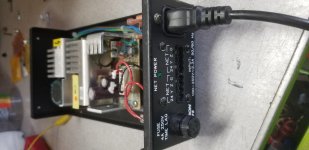
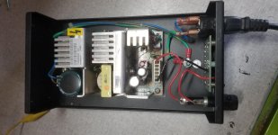
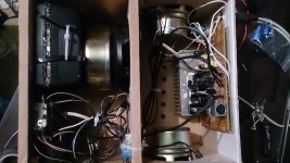
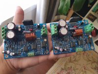
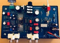
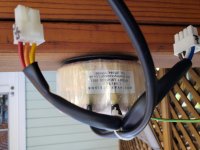
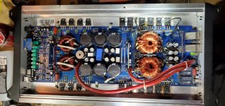
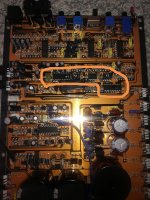
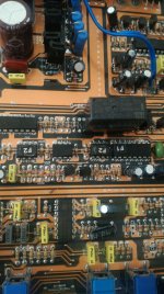
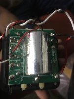
I pulled open the cover, and started looking over the insides:

- No debris, no dust even, so the PO obviously did some preliminary work
- Two of the eight BJTs on the board that wore heat sinks were missing them
- no electrolytic caps have burst or leaked, but a few of them exhibited a little bit of "pillowing" on top, where the "Mercedes logo" relief cut had a little hill in each of the three sections
- other than a tiny bit of what's probably cleaning residue near some clusters of BJTs (and nowhere near any caps), this board is pristine


My questions so far:

- I'm pretty sure the pots need to be cleaned. Especially that volume pot. I'm new to this and have never done that work. I have CRC/QD contact cleaner, MaxPro contact cleaner, and Deoxit F5 on hand. I'm sure that whichever one of these I try to use, it will be the wrong one, I'll put it in the wrong spot, it'll destroy the pot, and when I come back here to report it, everyone will say "why did you use that? You should have used (x product)!" so I figure I'd ask here first - what should I use, and how?

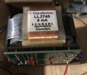
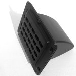
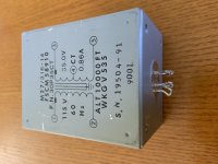
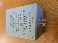
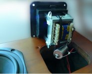
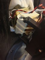
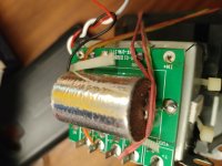
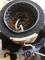
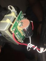
- Hafler used a frame-type transformer mounted diagonally in the back corner, so I can't convert to an IEC plug without major surgery (no room). Has anyone here done an IEC retrofit on the DH110, or at least upgraded to a better 3 wire cord?

- I'd like to source the caps myself. If I replace just a few caps, I should replace all 24 of them. The Hafler assembly manual parts list is riddled with typos and is not brain-friendly (the BJT list is especially badly done - whomever did it freely mixed up the letter I with the number 1). Would anyone here have a more concise list available?

- If I turn out to be not smart enough to figure out the cap values, is there anything wrong with going to "that guy" on eBay and buying the complete cap package for $43?

- What brand of capacitors are recommended? I am open-minded to both the arguments against esoteric caps as well as the arguments in favor of them. I think both have good points, but there's a law of diminishing returns. Silver sounds better than tin, but I can't tell the difference between gold and silver -and apparently some people can- is what I'm saying. So what "audiophile-grade" capacitors are a good value, if there is such a thing? I'm also open to buying a lot for a volume discount, if that helps.

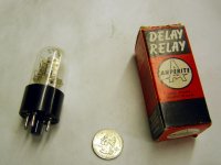
- Where do I find the goofy little stamped copper heat sinks for these BJTs? They're about 2/3 the size of postage stamps and made to fit TO-92 packages. They're probably pretty important.

Managing libraries in LTSpice

Until now I am confused about how to manage libraries in LTSpice, particularly if you prefer to use version IV.

How do you set the program to look for the latest library you provided, adding newer or not present parts?

LTSpice installs in two places by default: in Program Files and in Users/user name/My Documents. LTSpice XVII seems to find the latest library easily, but LTSpice IV does not.

Does anyone know how to set LTSpice IV to look for the right library?

Before anyone makes this question: I'm interested in keeping using LTS IV, no XVII.

Hifonics BRX 3016.1D waveforms

Ok so story on this one was blown power and audio section.

Right now the rectifiers are pulled and a 2 ohm resistor in series with 12v power. No current draw.

I am trying to understand what the attached waveforms are telling me, if they are ok and how to clean them up if they're not.


Replaced R106 and R107 on the Pwm card.

I didnt have any irf064ns but i did have a ton of IRFP3206's on hand.

8 Mosfets in power section changed to Irfp3206.

Gate resistors changed to 10Ω down from 22Ω.

8 drivers replaced with bd139 and bd140. Originally were the C3228 and complimentary pnp.

8 power supply Fets replaced from IRFP064N'S to IRFP3206.

4 pulldown resistors reduced from 470Ω to 220Ω which helped pul back down to ground.

Attachments

  • 20200223_204248.jpg
    20200223_204248.jpg
    346.9 KB · Views: 94
  • 20200223_210122.jpg
    20200223_210122.jpg
    316.4 KB · Views: 96
  • 20200223_203844.jpg
    20200223_203844.jpg
    257.4 KB · Views: 95
  • 20200222_164039.jpg
    20200222_164039.jpg
    985 KB · Views: 121
  • irfp3206pbf.pdf
    irfp3206pbf.pdf
    297.1 KB · Views: 54
  • irfp064npbf.pdf
    irfp064npbf.pdf
    598.5 KB · Views: 53

Regulator proximity to opamp

Hi I need to create a +-15V regulator for an opamp.
But I don't know what is the best for low noise, to have the regulator close to the opamp (lower impedance) or far away from the opamp to reduce noise ?
What is "industry standard".


What is the best :
BRIDGE > CRC > REGULATOR >>>>>>>>>>>>>>>>>>>>>>>>OPAMP
or
BRIDGE > CRC >>>>>>>>>>>>>>>>>>>>>>>> REGULATOR >OPAMP

Thank you.

FS: Alpha Big Boy PCB Set

Hi, Complete and untouched, Qty 2 PCB's Euro 60 / £50 with shipping worldwide.


Change of plans mean that these are available.

email me for more details

philip


Description

This is the ALPHA Big Boy with Buttah (ABBB) Class A Amplifier PCB. This amp is the evolution of the Alpha BB amp but combined with the popular Smooth Like Buttah (SLB) active bridge cap multiplier power supply all integrated on board. The amp uses the wonderful Aksa Lender front end with the superb hybrid P channel Aleph output stage. In combining the Alpha BB with the SLB we have essentially simplified one of the most time consuming and difficult aspects of building a Class A amp: making the power supply and connecting it. We have also decided to include a custom solid state relay (SSR) speaker protection and delayed start circuit designed by jhofland. The SSR protection is new and has been tested on P2P veroboard. Beautiful professional layout by JPS64 and includes over 16,000 vias that stitch the top and bottom copper planes together for a lower impedance path for electric current. Boards will be 2mm thick with 2oz copper and gold ENIG finish.


Notable features of the ABBB amplifier:
- All in-one amplifier board
- 52w into 8ohms
- Remotely mounted power transistors with Molex quick disconnects
- 400VA to 500VA 32v power transformer (per channel) with dual secondaries is recommend to achiev about +/-37v rails
- Designed to be used with cost effective CPU coolers
- Built in ground loop breaker using NTC and 22nF cap
- Bias current is circa 3 amps

Attachments

  • pcb 1.jpg
    pcb 1.jpg
    459.6 KB · Views: 241
  • pcb 2.jpg
    pcb 2.jpg
    712.7 KB · Views: 264

47 Single Ended Pentode Amp/Headphone Amp

So, having built a 6SN7 PP amp to power my HE-4xx planars (very power hungry), I wanted to build an amp for both headphones and effecient speakers with a little more power than the 1.5w 6SN7 PP.

I have decided on the 47 as my output tube which will more than likely be in Pentode or Ultralinear mode (maybe as switch two try both). I will be using a pair of Coleman regulators for the filament and cathode biasing I think I should be able to get close to 2w in pentode mode.

I am at the crossroads when it comes to the driver, however. I was originally going to use a 6C6 in Pentode with each screen regulated with a VR tube, but I started wondering if it would be difficult to keep the tube quiet (in pentode mode) for headphone use. I am not thinking of 7788 Triode strapped, with plate chokes and LED biasing, but I really wanted something that had that 1930s look to match the nice globe 47s.

I got a really nice pair of OPTs from Musical Power Supplies (Hifi version) with 4 and 32 ohm taps for under $100 US (cant beat that with a stick!)

I will be powder coating the chassis metallic gray and will probably coat the end bells Illusion Cherry, or Illusion Copper from Prismatic Powders.

Power supply will be CLC then each channel will branch off and have its own LC.

So, the big question is, how difficult would it be to get a 6C6 quiet enough in Pentode mode for headphone use? I have never used a Pentode driver (not triode strapped) before, so I dont have any experience with them.

FS: Elma 2-deck, 24-position switch (BV22568) for AVC/TVC

SOLD: Elma 2-deck, 24-position switch (BV22568) for AVC/TVC

This is an NOS, Swiss-made switch I intended for a passive preamp project, before I took an easier path by going with Dave Slagle's autoformers.

Unlike Elma's 04-2130 switch, the BV series were made for attenuator use and so are shorting switches - in other words, no pops or noise as you turn the volume knob.

Michael Percy used to sell these for $57 (+ shipping) back in 2003, and the 04-2130 for $46; today the BV series is no longer available and he wants $115 for the comparable 04-2133... Which go for roughly 80 Euros across the pond.

Asking $SOLD shipped within US.

Click for pix

Tannoy Eclipse (gold) farting woofer

So I got my hands on a nice pair of Tannoy Eclipse, the first version with the gold tweeter, and found that in one speaker the woofer farts, even at very low volume. Visually it looks as new, no tear and wear at all. I swapped the drivers and the other one sounds great in the same cabinet, so I guess the crossover is fine.

A fast check suggests the coil needs replacement, but I haven't managed to find any original replacement kit for it. What if I use a non-original coil that "fits" ? will it make the speakers sound different (and as such also cause phasing etc.) ?

Does it worth the effort at all ? I intended to use it as a small mixing monitor along with my Focals and NS10M, as "represents" the sound of a hi-fi system to me, and I love the sound.

Any advice?

FS: Abbot Tech Power Transformers

Hi,

I have two of these available.

Abbott Technologies 30P35CT 115V/60Hz 30VAC (35V/0.86A) Power Transformer. Condition is New. Shipped with USPS Priority Mail.

High quality hermetically sealed and still in production. Built like a tank. Good for 18V DC projects.

https://abbott-tech.com/wp-content/uploads/2019/07/P-Series-Catalog-Page.pdf

Price is $100 each + S&H OBO

Also on eBay:
Abbott Technologies 30P35CT 115V/60Hz 30VAC 35V @0.86A Power Transformer | eBay

Attachments

  • 6D37BF99-D930-4C11-906E-681C45B0CC19.jpg
    6D37BF99-D930-4C11-906E-681C45B0CC19.jpg
    477 KB · Views: 92
  • AD842D89-39E1-45A1-81ED-DA492967C4FE.jpg
    AD842D89-39E1-45A1-81ED-DA492967C4FE.jpg
    672.4 KB · Views: 97

Crossover recommendation needed

Hi,

I am building my 3 way openbaffle speakers and need advice on designing crossover, and may be a suitable tweeter (or super tweeter).

Current configuration is:
- Bass: Altec 416-8B (8 ohm 98db)
- Mid: Coral Flat 8a (8 ohm 96db)
- Tweeter: Saba greencone (5 ohm, unknown but more sensitive than Coral)

Attached are actual speaker (no tweeter attached yet) and planned crossover (with parts I got in hand). Among internet information, I am thinking to cross Altec up to 750Hz, and then Coral at around 7KHz or 10KHz.

This speaker will be used with tube amp 6C4C, supported by 02 Sub via B5 active crossover (can be config from 20Hz to 300Hz)

Any idea is welcome.
Thank you.

Attachments

  • speaker.jpg
    speaker.jpg
    299 KB · Views: 364
  • crossover.JPG
    crossover.JPG
    112.7 KB · Views: 362

Dayton Audio NHP25Ti-4

I'm helping a friend to design a 3 way hifi floorstander, and on the search for a good tweeter for this that is cheap i found this Dayton Audio NHP25Ti-4 tweeter that looks very promising on paper. But i can't find any real world reports about this one. Does anybody has experience with this tweeter down here?

Or can you sugest an other cheaper (<50€) tweeter that can be used for the +5kHz section, with an efficiency of min 92dB/2.83V/1m and has a good (not to sharp) sound. For mids we are mainly looking at Faital 3 or 4" drivers, and bass/sub will probally be SB Acoustics (but it's still open).

The user wants to use it with a passive crossover and a 16w tube amp, so high efficiency (+90dB) is needed, and dsp or high power class D amps are not an option for this for the user so it's useless to suggest drivers that will need those.

Some of filter questions

My filter theory is old and rusty but I got the basics about first order, second order, third order hpf and lpf two-way designs. But my recent projects need some additional knowledge.

1. Three way crossover.

I like to buy pre-assembly but this time I also want to have flexibility in case I will go back to two way. I need a simple crossover at 500hz and 3500hz. Can I serial couple 2x 2-way crossover to get the same result as a 3 way connecting the 500Hz hp to the 3500hz input or will it mess with the 3500hz filter and the slopes? If I add a variable resistance authentication to the treble will the crossover frequency go up or down (just trying to avoid LPad) and what kind of overprotection fuse/compression would you recommend for a Eminence APT50 HF driver?

2. Shelving low pass (high frequency shelving authentication).

I have a full range driver that I want to authenticate -6dB starting at 1000Hz (meaning the -6 point at approx 1800hz) and flat from 1800 using this example below - do I absolutely need a R1 or can I just parallel connect a capacitor of the crossover point 1800hz and a resistance of 8 ohm? What would actually be the value of the capacitor in 8ohm system.

https://www.linkwitzlab.com/images/graphics/passive_down_shelf.jpg

Sorry for the bad language, hope you understand my questions.

Need advice on midrange driver

Hello everyone,

I am new to this forum and need some advice for a midrange driver in a 3 way system.

The woofer i will be using will be a 8 inch Monacor woofer:
MONACOR: SPH-220HQ

The tweeter will be a ribbon tweeter from Monacor:
MONACOR: RBT-35SR

Can anybody give me some advice on size and maybe a specific driver to use in this system?

Thank you in advance!

Replacement Capacitor

Hoping the experts in here can help me. I happen to have a Gallo acoustic classico CL-4 speaker. The tweeter inside one of the speakers is not working. The cause seems to be the capacitor. No values are written on the capacitor.

Here is some mumbo jumbo I happen to find on a website regarding this capacitor.

"We again run a DC blocking capacitor on our now 180° dispersion film tweeter for amplifier protection. The quality of this cap is ultra important since it also operates as a small voltage divider on a purely capacitive driver. By the time we get to the Classico IV this part becomes a very costly TRT Stealthcap unit from Peter Moncrieff."

1) Is it possible to measure a capacitor and get values like capacitance and Vdc from it.

2) Would it be okay if I use a capacitor with the same values but from a different brand. Risky, cause it says the cap is for amp protection. The original caps cost in the line of $150 for a single one.Will it change the sound signature?
Which caps would you recommend and where can I get them. Please note the cap functions as a DC block cap and also as a small voltage divider on a purely capacitive driver.

3)I assume I need to replace capacitors on both speakers.

Valuable inputs are much appreciated. I'm new to all this as well. Pics of the capacitor and the tweeter. The tweeter is attached to a transformer which is then attached to the capacitor.

Attachments

  • sdsds.jpg
    sdsds.jpg
    49.7 KB · Views: 225
  • 84793921_240788130254587_6689423125571960832_o.jpg
    84793921_240788130254587_6689423125571960832_o.jpg
    54.2 KB · Views: 219
  • 20200221_104216.jpg
    20200221_104216.jpg
    771 KB · Views: 272
  • IMG-20200222-WA0000.jpg
    IMG-20200222-WA0000.jpg
    59.8 KB · Views: 227
  • IMG-20200222-WA0001.jpg
    IMG-20200222-WA0001.jpg
    110.9 KB · Views: 221
  • IMG-20200222-WA0002.jpg
    IMG-20200222-WA0002.jpg
    69.5 KB · Views: 146
Projects by fanatics, for fanatics
Get answers and advice for everyone wanting to learn the art of audio.
Join the Community
507,574
Members
7,877,713
Messages

Filter

Forum Statistics

Threads
405,764
Messages
7,877,713
Members
507,574
Latest member
Sha1rholder