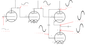
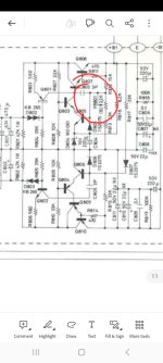
Looking through a lot of relatively new circuit designs of valve amplifiers, the Constant Current Source takes almost all the leading position. Except those used in Filament CCS, almost all other designs are Cascode ones.
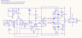
For example like this, the M3 and J1-J4 formed a Cascode CCS.
If we set it at 10mA and using DN2540 at M3, the FET at J1-J4 position could only get a Vds even below 1.5Volts, which can't drive the FETs into saturation area.
If the lower side FET can't go into saturation area, how could it deliver a constant current?
These new SiC JFETs entirely eliminated such problem. The Vgsoff of these transistors is typically -9Volts, which means you'll have over 8Volts for the lower side.
I could say these SiC JFETs fully "liberate" the lower side conponents, providing a better working condition(Over 8.7Volts for 25mA) comparing with traditional Depletion MOSFETs such as DN2540(lower than 1Volts for 25mA) and IXCP10M90S(About 2.4Volts for 25mA). Even LM317 could be used here for a higher current accuracy.
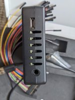
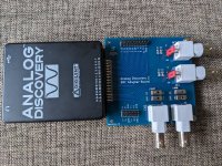
I've bought some samples of the 650V 80mΩ version, and give it to my friend replacing DN2540 in the Mu Follower design. Now his only remainging question is what to use at the lower side
😀.
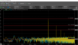
The problems of the SiC JFETs are also clear.
The capacitance is the biggest one. The Rdson=80mΩ version has a Crss of 88pF, while the Crss of Rdson=400mΩ version is 18pF. It's much higher comparing with DN2540.
Maybe packaging the UJ3N1701K2 is the ultimate solution
😵
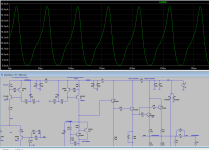
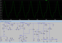
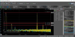
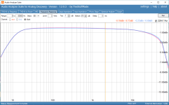
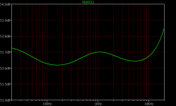
Here's the curves I traced with DTT-X of UJ3N065080K3S.
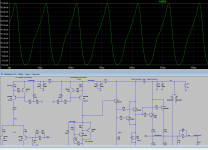
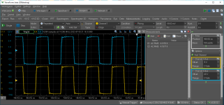
These two are the characteristics of UJ3N170400B7S.
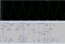
And I also managed to trace the output characteristics in high voltage area of UJ3N065080K3S with etracer. Since it's not easy setting, I've only scanned the curves when Vgs=-9.0V.
Notice that Vgs should be provided externally and previously, because the normally-on state of JFETs will trigger the Short Circuit Detection of etracer.
It's not as horizontal as DN2540, so Cascode is necessary.