Im going through the gain stages of my amp, just to get a grip of each amplification stage. Trying to understand how the coupling caps effect the phase going into the last stage of preamplification...
Strange as I see it, the last coupling cap would have 2 signals 90 degree's out of phase... I must be missing something?
Really started because I couldn't find any information about the tube config (long tail, cascode etc..) that fit the last stage in this 12AU7 config..
Do tubes (grid to plate vs grid to cathode) change the phase that Im not accounting for ?
Attachments
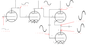
I believe i illustrated that in my attachment correctly. My question may be should have specified phase shift as well. It appears to me that the last stage of preamplification is combining 2 signals 90 degrees out of phase (not inverted).. again i could not find any documentation on how the last tube behaves when wired as it is, and made a best effort stab on whats happening..
I still think something is off, my knowledge, the circuit or both lol
I still think something is off, my knowledge, the circuit or both lol
Is phase shift always only inverting when comparing grid-anode vs grid cathode or is there additional shifting in phase or out of phase?
A signal through a coupling cap vs same signal without, the coupling cap causes a shift of 90° from what I have read..
A signal through a coupling cap vs same signal without, the coupling cap causes a shift of 90° from what I have read..
Yes, but it is frequency dependent and you choose the coupling caps minimise the effect.

The phase is inverting or not as mentioned above.
Phase shift through a coupling cap will only happen at the LF side when the impedance of the cap gets in the same ballpark as the load the cap is facing.
You'd normally chose a coupling cap value to avoid phase shift down to below say 10Hz.
Upshot is that cpupling cap phase shift doesn't come into play except at very low frequencies. Assuming a competently designed amp.
The phase shift through a cap is exactly 90deg when the cap impedance is equal to the cap's load impedance at that freq. Above this freq the phase shift is less, below this freq it is more.
This is also the freq at which the freq response has dropped 3dB.
Isn't physics beautiful
Jan
Last edited:
Thank you all... and physics is only beautiful when you can see it lol.. Im still teething but will certainly try to internalize all of this.. at one point lol..
i have seen a bunch of videos explaining tubes, read the beginner books enough to follow along. That last stage with the 12AT7 with the cathode of one section tied to the anode of the other and no coupling cap on grid of upper section really is beyond my understanding. Im hoping to find a somewhat deeper explanation..
So what i figure is the way its setup both sections are working in parallel to some degree. I cant tell if its to increase the voltage swing or current (both?)
I have heard that the 300b needs a pretty decent driving stage...
Actually with the capacitor impedance equal to the load resistance you get 45deg of phase shift. The capacitor must have a much higher impedance than the load resistance to see 90deg.
The terms phase shift and polarity are two completely unrelated things.
For example, in a common cathode circuit, the signal at the plate is of the opposite polarity,
compared to the input signal at the grid. This is also called inverted, but it is not due to phase shift.
The output signal polarity flips due to the nature of the circuit topology.
The signal at the output of a coupling capacitor can have some degrees of phase shift (a larger or smaller amount),
relative to the signal at the capacitor input terminal, depending on the component values and input frequency.
But both signals will still be of the same polarity, regardless of the input frequency.
Also, there is a continuous range of possible phase shift values; for example, 0 to 90 degrees for a coupling capacitor.
Phase shift will depend on frequency unless there are only pure resistances in the circuit, when it will be zero.
But there are only two possible signal polarities, positive and negative (or if you prefer, inverted).
The polarity does not depend on frequency.
Last edited:
😎😎
Jan
Yes, I was wrong. Thanks.Actually with the capacitor impedance equal to the load resistance you get 45deg of phase shift. The capacitor must have a much higher impedance than the load resistance to see 90deg.
Jan
One good way to get understanding I often use is to pencil in the DC voltages at the tube connections. At a certain point you start to see things like Vgk that determine grid bias, and for instance voltage across Rk that determine Ik (or vice versa). Just start at the beginning and work towards the output.Thank you all... and physics is only beautiful when you can see it lol.. Im still teething but will certainly try to internalize all of this.. at one point lol..
i have seen a bunch of videos explaining tubes, read the beginner books enough to follow along. That last stage with the 12AT7 with the cathode of one section tied to the anode of the other and no coupling cap on grid of upper section really is beyond my understanding. Im hoping to find a somewhat deeper explanation..
So what i figure is the way its setup both sections are working in parallel to some degree. I cant tell if its to increase the voltage swing or current (both?)
I have heard that the 300b needs a pretty decent driving stage...
If you post the whole schematic we can help with that.
Jan
jan, TY again... It always seams as though as soon as I post the schematic, the thread always falls apart and dies lol!
No one likes to talk about the chi-fi stuff 😵
Purchased for an education, and im getting one for sure...
Turns out, Uncle doug has a video about Phase Inverters, and from the drawings he had in the video, my 12AU7s look to be wired up as a paraphase phase inverter..
I will look up the schematic for the fender 5c3 deluxe or newcomb amp to see how the cathodes compare to be sure...
I had penciled in the voltages few times, but in all honesty was a pretty big endeavor to check the entire amp and document all of the voltages in one go.
I kept getting inconstant readings, which I believe is now fixed as well..
I plan on going in again once I have more than a few hours....
Poking around measuring voltages really doesn't tell me what Im supposed to be seeing, only whats there.
I kind of feel like if I have a better grip of how and why, I might be able to deduce if what Im seeing is more or less in line with whats ideal...
Finally have a stable 300B amp, no disapearing channels ... I was loosing heater voltage on one channel of my 300B's, than after fixing that, the other side would give me a problem. turns out I think the PCB traces were flaky.. Off board duplication of the heater circuit has been 100% rock solid for a while now..
Before I was having any troubles, amp sounded fantastic w/o GNF or LNF.. Now, not so much but the GNF and LNF clamp down too much... almost sounds compressed
Yeah it's scary to be thrown in at the deep end.
But in the end there's no easy shortcut to understanding, you've got to put in your time.
As we say in our country: "if you think education is time consuming and expensive, try ignorance".
I appreciate your search for understanding, that puts you ahead of the majority here.
Jan
But in the end there's no easy shortcut to understanding, you've got to put in your time.
As we say in our country: "if you think education is time consuming and expensive, try ignorance".
I appreciate your search for understanding, that puts you ahead of the majority here.
Jan
Unfortunalty, it looks like the paraphase phase inverter looks like the plates of both sections are driving the next stage,
while in my amp the cathode of one stage is wired to the plate of the other.. Still an unknown to me layout..
Can anyone point to any educational material with this layout?
while in my amp the cathode of one stage is wired to the plate of the other.. Still an unknown to me layout..
Can anyone point to any educational material with this layout?
Please focus on the amplifier that is in question, it appears to be an actual circuit that sometimes works, sometimes has to be fixed, and that the original poster is modifying.
That means we really need a complete and accurate schematic of that amplifier and that power supply.
Anything less than that is just like a blindfolded archer trying to hit the 25mm bullseye at 50 meters.
This thread will go around the world and back, before the original amplifier is analyzed, working, modified, and results are predicted and verified.
jan.didden,
You said:
"The phase shift through a cap is exactly 90deg when the cap impedance is equal to the cap's load impedance at that freq. Above this freq the phase shift is less, below this freq it is more."
Starting with a capacitor that is in series with a resistor (such as the RC coupling from one tube's plate to the next tube's grid):
Xc is capacitive reactance, def.
R load is a resistive load, def.
At a frequency where Xc = R load, then the phase is 45 degrees, and the attenuation is 3dB (that is a benchmark for electronic crossovers, single pole woofer and single pole tweeter passive crossovers, RC plate to grid coupling, etc.).
For a singe pole, 90 degrees phase shift is when the R load is zero Ohms (much much much less than Xc). And, the attenuation is infinite.
So the signal may be 90 degree phase shifted, but since there is no signal output, the 90 degrees is a moot point (pointless, except for the math discussion).
For a singe pole, 0 degrees phase shift is when the R load is infinite Ohms (much much much more than Xc). And, the attenuation is 0 dB.
Everything else falls in between those extremes.
Simply said , without significant current flowing in the cap there is no phase shift .
A low impedance output stage connected to a cap will produce 90deg phase shift , usually the cap is ( small ) stray capacitance so the phase shift is at high frequency .
A low impedance output stage connected to a cap will produce 90deg phase shift , usually the cap is ( small ) stray capacitance so the phase shift is at high frequency .
Last edited:
depanatoru,
Do some research about capacitors.
At DC, a capacitor's impedance is extremely high; the only currents that flow are:
When the DC voltage is applied (cap is charging),
When the DC voltage is removed (cap is discharging).
When there is leakage resistance.
At high frequency, capacitive reactance is very low [at extremely high frequency, the capacitor approaches a short circuit, except for the series parasitic inductance].
- Home
- Amplifiers
- Tubes / Valves
- Gain stage and phase