Help me revive a 2.1 system
Long story short, I have had a Boston Acoustics Soundware XS cinema 2.1 in my RV for many years. It was perfect, except for the gaping hole of mids that it missed because it has little cubes and an 8" sub.
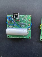
Well, it finally died in a rather crispy fashion. Sometimes it works, other times it likes to smell funny and quit playing. I stripped all the SP and amp off the plate and I want to cut a new plate and re-power it.... mostly because I hate throwing away perfectly good drivers. I'll use the cubes for some other project and instead use some c-notes I just put together for L/R.
Looking for a board amp (or a standalone that I can hack) to repower this 2.1.
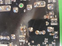
I found a ton of very questionable (sketchy AF) choices on Amazon with dubious reviews, but thought you folks might know a good bet for what I'm looking for. I thought about repairing it, but nothing looks obviously damaged, and I'm only fair with a soldering iron.

Well, it finally died in a rather crispy fashion. Sometimes it works, other times it likes to smell funny and quit playing. I stripped all the SP and amp off the plate and I want to cut a new plate and re-power it.... mostly because I hate throwing away perfectly good drivers. I'll use the cubes for some other project and instead use some c-notes I just put together for L/R.
Looking for a board amp (or a standalone that I can hack) to repower this 2.1.
- Thinking somewhere in the neighborhood of 50-plus wrms for L/R and around 100wrms for the sub
- It doubles as a music source, so bluetooth would be lovely. I really don't like BT, but it beats having my phone tethered to the plate.
- should have an adjustable crossover so I can match the c-notes to the sub
- RCA or 3.5mm input is fine. TV is old enough that it doesn't have optical
I found a ton of very questionable (sketchy AF) choices on Amazon with dubious reviews, but thought you folks might know a good bet for what I'm looking for. I thought about repairing it, but nothing looks obviously damaged, and I'm only fair with a soldering iron.