Hi,
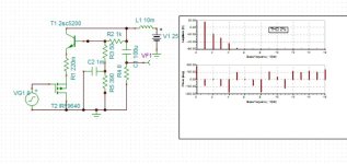
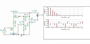
I'm playing around the simulation of a single-stage class A mosfet amp with triode curves, an efficiency close to 50% and a Zout around 0.38 Ohm.
I've used the same concept in two stage tube amps doing what @Tubelab_com did on pentodes, but here I would like to apply to a simpler low voltage circuit.
On LTSPICE (file attached) results are very good:
I would like to have suggestions from you more experienced people concerning the feasibility of the circuit and the choice of the best components for it.
Most critical parts seems to me the choke (is the Hammond 193U a good choice?) and the mosfets: the p-mosfet should be able to dissipate 10 W and each of the two n-mosfets 20 W each.
Thanks in advance for your help.
Roberto

I'm playing around the simulation of a single-stage class A mosfet amp with triode curves, an efficiency close to 50% and a Zout around 0.38 Ohm.
I've used the same concept in two stage tube amps doing what @Tubelab_com did on pentodes, but here I would like to apply to a simpler low voltage circuit.
On LTSPICE (file attached) results are very good:
- a Zout of 0.38 Ohm (so a DF of 21)
- 0,09% THD at 1 Wrms with 180 mVrms at its input (all harmonics fall 20 dB below the previous one)
- 0.47% THD at 10 Wrms (all harmonics fall 8 dB below the previous one)
- 5% THD at 20 Wrms. This is due to the error only feedback that scales down the output and subtracts the input signal to in, in order to have only the error to inject as feedback: no loss of sensitivity for the amp while increasing the DF and reducing the THD.
I would like to have suggestions from you more experienced people concerning the feasibility of the circuit and the choice of the best components for it.
Most critical parts seems to me the choke (is the Hammond 193U a good choice?) and the mosfets: the p-mosfet should be able to dissipate 10 W and each of the two n-mosfets 20 W each.
Thanks in advance for your help.
Roberto
Attachments
The topology is in accord with a (historic) simple triode amplifier - without output transformer, but mosfets are no triodes.
Your claim...
Lots of work in the loop around U1 - can you draw a more traditional circuit instead of this foldup view?
Your claim...
... is not valid.with triode curves
Lots of work in the loop around U1 - can you draw a more traditional circuit instead of this foldup view?
Yes, n-mosfet have triode-like curves in this configuration by applying local feedback from drain to gate, and driving them from the source through a p-mosfet source follower.
That's not in the circuit drawing visible. There's only V1 connected to the output of U1, which is low-Z indeed.from drain to gate
So the mesmerizing circuitry around U1 is to mimic the triode output thing, but not its transfer really.
Can you supply a more solid proof of your claim, formulas, extended simulations, and the like?
No, R1 and R4 is the local feeeback.
Please read better the first post.
Take a look at this thread @ra7 :
https://www.diyaudio.com/community/threads/schade-common-gate-scg-preamp.380487/
Please read better the first post.
Take a look at this thread @ra7 :
https://www.diyaudio.com/community/threads/schade-common-gate-scg-preamp.380487/
Last edited:
ok, that's a cascode with the bottom p-mos reversed (hmm) and the upper with a ultimate simple d-g feedback, yields in an reciproke triode curve
good luck
good luck
it is
u1 is grappling the output, V1 ('9.2') is adding to the topping n-mos'
expecting... not anticipating
this triode-trickering is known for the last 40 odd years now
u1 is grappling the output, V1 ('9.2') is adding to the topping n-mos'
expecting... not anticipating
this triode-trickering is known for the last 40 odd years now
As Zintolo states it is possible to make nice looking triode curves with a Pentode vacuum tube or an N channel mosfet that has its drive signal applied to the cathode or source from a low impedance source like a transformer or P channel source follower stood on its head. Local negative (Schade style) feedback applied from the plate or drain to the grid or gate transforms the typical pentode curves into very convincing triode curves in the manner that Schade detailed in his technical paper from 1939.The topology is in accord with a (historic) simple triode amplifier - without output transformer, but mosfets are no triodes.
Your claim... ... is not valid.
Lots of work in the loop around U1 - can you draw a more traditional circuit instead of this foldup view?
In my version of this I use s simple resistive divider between the plate and cathode with a tap at about 10% feeding the grid. I do not use the opamp stuff for another feedback path. I have made several triode like amplifiers using vacuum tubes and mosfets. Many of the details are scattered throughout the SCG preamp thread.
https://www.diyaudio.com/community/threads/schade-common-gate-scg-preamp.380487/page-4
Am I looking at this correctly? It looks like a single stage rush cascode using MOSFETs, with a variable reference point for the top FETs' negative feedback. The LT1178 seems to have many undesirable characteristics in this application, though.
H
HAYK
I tried out the rush cascode with pmos and nmos for a gain of 7 biased about 1A. The THD is 7% for 7vp.
With pmos and npn, gain 6, I get 2% for 6vp.
I don't know how the bias is temperature stabilized for nmos, I would use an NTC, with npn, it might not be necessary.
With pmos and npn, gain 6, I get 2% for 6vp.
I don't know how the bias is temperature stabilized for nmos, I would use an NTC, with npn, it might not be necessary.
Attachments
Indeed that would be a LM4562, I simply don't have it on LTSPICE.The LT1178 seems to have many undesirable characteristics in this application, though.
For tweeters the OPAMP feedback is not strictly needed and it works with that simple R1&R4 local feedback.I would make it 5W-10W tweeter amp in open loop.
The choke can be way smaller (so cheaper) or even substitued by a CCS (even cheaper, and efficiency is not such a problem with low wattages).
I've found it useful for triode+unset amps, that's why I added it here. Without it the DF is around 2 IIRC.I do not use the opamp stuff for another feedback path.
I've seen you usually prefer the mosfet to work at high voltages and loaded by an output transformer.I have made several triode like amplifiers using vacuum tubes and mosfets.
Do you see benefits in using it? What I would try to do is avoid the output transformer (so its 1/75 gain factor) in order to avoid the driver too.
And then of course the fact that low voltages are easier to handle and there's more choice on mosfets.
Indeed mosfet choice is one of my problems, not being an EE.
Anyone can help me on this point?
Thanks in advance
Roberto
H
HAYK
H
HAYK
I've not played that much with simulations, but different pentodes at different working points caused different phases of the 2nd harmonic.
It should be the same with mosfets as well. Have you tried increasing the bias current?
It should be the same with mosfets as well. Have you tried increasing the bias current?
Last edited:
- Home
- Amplifiers
- Solid State
- Single-stage class A 20 wRMS mosfet-amp: can you help me to develop it?


