JL1000/1 - 15 second turn on delay

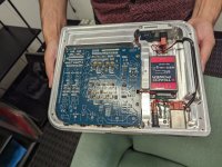
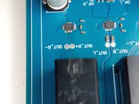
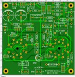
A question for @Perry Babin or other gurus here - I'm working on a JL 1000/1 that had corrosion and other damage in the startup circuit area, on the daughter board in the area that sits above the power terminals (pretty common, from my understanding).

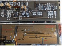
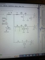
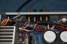
I repaired all of the continuity issues I could find - see the pics. The ground plane was actually burnt open in three locations on the daughter board due to the previous owner directly gouging into the ground plane from the positive terminal below (I think). I also found two open traces in the area due to corroded vias, and one blown NPN transistor (original part was marked ZC) sitting near the LM324.

After fixing these continuity issues and replacing the NPN, when I place the daughter-board back onto the main amp board and apply remote, the green led lights right away, but nothing else 'starts' until an approximate 15 second delay. The red and yellow leds flash for a moment when this happens. When I place the daughter board into a known good 1000/1 (all boards same revs) I get the same delay, whereas when using the good amp's normal daughter board the amp 'starts' in less than 3 seconds as expected.

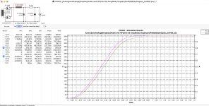
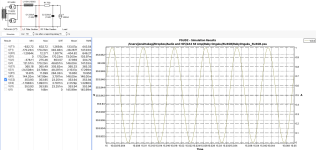
I also noticed that in the 'bad' amp the supply voltage on pin 6 of the header (in my pic, the pin with the orange jumper wire soldered on) does not pull low when remote is removed - it stays up as long as main +12V to battery is present. Whereas in the good amp it pulls low as soon as remote is removed. It looks like this pin is fed through a 4.7ohm resistor from the positive supply plane after the choke on the main board, so maybe this could be a clue...

Any advice would be appreciated. Has this delayed start behavior been seen by others?
Thanks, Cheers

Attachments

  • JL 1000_1 Start Circuit.JPG
    JL 1000_1 Start Circuit.JPG
    252.2 KB · Views: 91

free audio gear, woofer blowout, near York PA

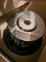
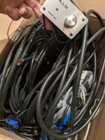
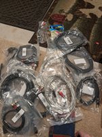
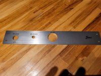
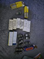
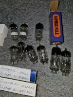
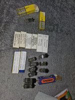
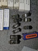
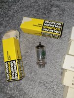
Clearing out storage. Every RCA cable and adapter cable known to man NIB (decent quality, free). A bunch of free totally functional 2a3 and I think 12au7 and similar tubes. Some Alon black cat speaker cable that originally went for several hundred(free). Several feet of Canare4s. Couple small amplifiers (free) Also panasonic sa-xr57 - class D receiver, sounds nice, just needs power cord (free). Banana's resistors, some caps, all unused. Also have high end woofers I'm clearing out.

12ps32 ($200 at PE, $100 each) new
7 Tangband w4-1320 woofers - NIB $30 ea (3 remain)
DIYMA12 subwoofer (what a beast) $100
2 B&C 15" 15nld76 woofers NIB $125 ea
DE45 compression drivers $50 (ea)
Usher 1001 10" woofers (4) ($75)
SOLD behringer ultracurve pro 2496 equalizers (2) unused $100 ea

all of this is 50%+ off and items are new.

Attachments

  • PXL_20230918_234244198.jpg
    PXL_20230918_234244198.jpg
    413.8 KB · Views: 203
  • PXL_20230918_235349961.jpg
    PXL_20230918_235349961.jpg
    387.6 KB · Views: 180
  • PXL_20230919_010430368.jpg
    PXL_20230919_010430368.jpg
    472.7 KB · Views: 203
  • PXL_20230919_000203402.jpg
    PXL_20230919_000203402.jpg
    635 KB · Views: 193
  • PXL_20230919_000853307.jpg
    PXL_20230919_000853307.jpg
    581.3 KB · Views: 197

Schematic wanted for push-pull triode connected pentode amp with DHT front end

I am looking for a schematic for a pair of triode connected pentodes, EL84, EL34, 6L6 etc. with a DHT front end, and some sort of a phase splitter (with gain if required). I haven't found any, and was wondering if anyone has tried this. I built a single ended amp with a Type 30 driving a triode connected EL84, and really like it, and am wondering if anyone has done this sort of thing with a push pull amp. Lots of indirectly heated tubes in front of push pull DHTs, but not much of the other way around.

Beveridge fan trivia

I saw this note from Rick Beveridge on the google users group for Beveridge loudspeakers- I thoughf it would be of interest:

Rick​

unread,
Aug 31, 2005, 7:28:40 PM


to beveridge-audio
There has been disagreement regarding whether the amplifier cooling
fans in the Model 2, and it's subsequent versions, about whether the
fan should be pushing air out of the amp or pushing the air into it.
I was working with my father when he worked all this out.
He intended that the fans draw cool air in from the back and push it
directly onto the tubes themselves. This heated air would rise and be
pushed out at the top along the front and sides by the air coming in
the back. It was his objective to create the thinnest possible boundry
layer of heated air around the tubes. He also reasoned that the air
from the back would bring in less dust this way.
Reversing this flow draws air in from the front and sides and then
pulls it through all parts of the amp before it is pushed out the back.
This draws the air from up high in the amp and forces it out at a lower
elevation out the back. Only a fraction of the air that the fan is
moving actually gets near the tubes which are the main source of heat.
This flow path is also contrary to the natural force of convection.
My brother Ross has experimented doing it both ways. I hope he will
describe his findings in a future post to this thread.
I am very glad to have this forum for us to share our knowledge of
these very unconventional speaker systems.
"...and the beat goes on..." Rick Beveridge

I know many users place their amps on top so this is not so important to them. I was curious about the best way to handle it though.

Two separated subwoofers - Advantage to stereo vs. mono vis-a-vis time alignment or level-matching?

Hey, all...

I have two 8-inch subwoofers in the rear corners of my hatchback. Like this (in green):
View attachment 402968

I'm currently running them 2-ohm mono, but I have plenty of channels and power to run them 4-ohm stereo.

Here's my question: Given their respective distances from the driver's seat, would there be a sound-quality advantage to running them stereo--not necessarily for left/right separation (although I'm open to hearing an argument for that), but more for time-alignment and level matching to the driver's position?

Thanks for your thoughts!

Custom preamp with 417A / 5842 phono stage

Erno Borbely designed a FET phono stage that was later adapted for tubes by Joe Tritschler (aufioXpress Jan 2010). I had two PCBs made with his circuit, but with a couple of mods including the ability to add Lundahl step-up transformers and switch between MM & MC cartridges.

I put the phono stage into one of my chassis, along with a modified Erhard PAS Akido line stage, a HV regulator, and an input relay PCB that I had made. The input PCB automatically shorts out unused inputs.

Also included is an IR remote-controlled volume control with mute function. An external power supply provides 12V and 358V that will be regulated to 300V for the two gain PCBs.

Rear Panel 8.jpeg
Pre open top view.jpeg
Front view no top.jpeg

Digital noise/interference on the left channel

Hi everyone,

I've recently assembled a breadboard DAC prototype based on the AD1862s with an AD811 I/V stage, when I test this board with my headphone amplifier board it seems to work fine.
I've also tried to add preamp and equalizer stages from Yamaha and Behringer in the middle (between the DAC and HP amp board) and everything is also ok, no sound issues, even if I move the sliders or knobs all way up or down.

Now I'm trying to put a preamp breadboard between the DAC prototype and HP amp (to perform some small L/R balance, volume and tone controls). I've noticed that whenever I play some sound or music in the DAC board I get an hiss, white noise like, on the left channel which is really anoying, even when I turn the preamp input pot all the way down, the noise is still there and it is only present when audio is being played, I don't know what is going on, since the right channel seems fine. It gets worse if I add some treble gain. Any ideas of what should I look for?

All the Best,
Danny

attaching front baffle without screwing

Hello all,
I am building a speaker box where I want to make front baffle removable. The baffle will hold two 12" or 15" or 18" woofers so it will be heavy. baffle is either 18mm or 25mm think MDF. As it will be removed for several times, I am afraid the screw holes will loosen up. I want to know what alternate methods available other than screws? I can think of using D-nuts or T-nuts. Any other options available?
Thanks
Shiva

Strong noise floor when the mic is connected to the microcontroller

I have made 2 recordings with the same microphone once with the
power supply from the lab power supply 3.3V. There the noise is
clearly smaller. And once after a 230V / 5V power supply for the
microcontroller and from the microcontroller the 3.3V. And there I have almost
30dB more noise on it.
How do I get the noise reduced?

On the board of the microcontroller I found in the schematic the power
power supply.
There is a +3.3V 400mA regulator of the type: TPS73633DRB
Enclosed the link from the datasheet:
https://www.ti.com/lit/ds/symlink/tps736.pdf?ts=1681424936822

MEMS am uC RMS -22.65.png


MEMS am LaborNT RMS -47.68.png


I have the noise with all my 3 different microphones. MAX4466 Breakout, SparkFun Analog MEMS Microphone Breakout - ICS-40180 and MAX9814 Breakout. But I would like to eventually build one myself using this guide:
https://www.ti.com/lit/ug/tidu765/tidu765.pdf?ts=1681525964125

Feedback on first 3 way Faital Pro cross over design please

Hi all, long time lurker and first time poster.
I’m designing a 3 way speaker, using all faitalpro 12fe300, M5N8-80, and hf100 with sth100 horn.
As this is my first diy, I’d like some opinions and to see if it’d work before I pull the trigger and buy all the parts.
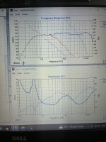
I’ve ripped the frequency responses and impedance graphs off the faitalpro website. Using fpgraph tracer I made my own zma and frd files, and used xsim’s predicted phase.
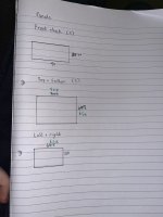
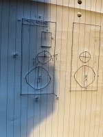
The 5” m5n8 will have a small box around it made of the same 18mm mdf that the rest of the box will be made out of. Port is 30cm by 5cm by 3.9cm deep tuned to 50hz In a roughly 220L box.
Pictures attached are frequency response on xsim , impedance, and dimensions.
I’ll be attaching a 4ohm resistor before the amp when plugging into an 8-16ohm300w amp before I get a 2-8ohm tpa3255amp(where I will stop using the 4ohm resistor, I’ll get a high wattage resistor). Will I blow anything up? Lol
Thanks in advance, all help will be appreciated.

Attachments

  • IMG_0539.jpeg
    IMG_0539.jpeg
    978.6 KB · Views: 177
  • IMG_0537.jpeg
    IMG_0537.jpeg
    381.7 KB · Views: 200
  • IMG_0602.jpeg
    IMG_0602.jpeg
    172.4 KB · Views: 159
  • IMG_0498.jpeg
    IMG_0498.jpeg
    1 MB · Views: 192
  • Like
Reactions: usa_satriani

I've been to the top of audio everest

Hello all,

Yes, audio enthusiasts, the tippy top of our audio goal and the quest for the sonic holy grail, has been seen and heard, if, however, for a short period of time. And what a listening experience it was.

While on a recent vacation trip to Colorado to visit my son, who now lives there, we were making a list of sights to visit and see, among other easy paced activities. Before we left NY, my son suggested and scheduled visits to a couple audio manufacturers in the area. We were visiting family in Boulder and for these two factory tours, my son Corey called ahead and made arrangements for Wednesday. I had heard of one of these manufacturers, but not the other. The first visit was to PS Audio, and the second was to Boulder Amplifiers(BA). Let me say this for starters; had BA been first on our list, my son and I would likely have not made it to PS Audio, and, still be listening in the sound room at BA, 7 days later when our trip ended.

BA builds several very high-end audio products. Their flagship product is the Model 3050, 1500W Mono Block amplifier. This is a work of art as much as it is an amplifier. Craftsmanship is outstanding and superbly executed. Some of the physical specs;

o 22.6" wide
o 13.4" high
o 34.7" deep
o 450 lbs each
o solid granite base, 75 lbs
o current price: $205K dollars

Full specs can be found here.

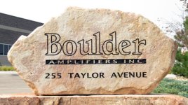
As we arrived at BA - in a typical business/manufacturing park in Louisville, CO we were met in the small lobby (very understated), by a very nice, energetic, and well-spoken young man named Kenzo. I'd say around 30ish yrs old, and he ended up being a most knowledgeable and gracious host. We exchanged names and he told us a bit about BA. He told us we'd see all aspects of the manufacturing process, and pictures were welcome. We armed our smartphones!

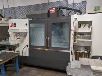
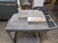
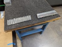
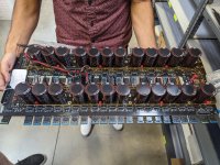
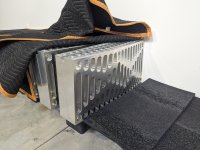
He walked us through, the entirety of their manufacturing process, starting with the milling machines. These are used with raw billets of aluminum (various sizes), which are milled to the specification of each part. One machine was running and milling a small aluminum part used in their proprietary gain stage. He showed us rooms with both raw billets and freshly milled small parts where fine hand sanding is done, and parts stored. Many internal parts of their amps are milled from aluminum as well (think internal resistor supports). Even the remotes are milled in-house. We moved on to a much larger(I don't want to call it a room, as much as a space). This was cylindrical in shape with one end sealed, and the other with a door. It was around 8-10ft in diameter, and roughly 14ft long. This was where the glass-sanding (bead-blasting) was done, by hand, to the massive side heat sinks, and top and bottoms of the amps. Glass beads are used to deliver a more uniform and evenly smooth finish. They farm out the anodizing process to another firm in the Denver area.

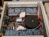
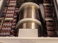
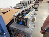
He moved us along and showed us soldering stations where thru-hole (and some SMD) parts are soldered to various PCBs. He also showed us the electronic parts inventory area, where they keep parts on hand for amps and other device that date back 25 or more years. We then moved on see how the massive toroidal power transformers are cased in black epoxy/resin substance that hardens and keeps the humming and vibrations down. No surprise their largest amp the 3050, uses 4 of these massive transformers in one cylindrical tube. Kenzo was not sure of the weight of the raw transformer, but he let me hold one and I'd say, easily 20-25lbs each. The 3050 outputs 1500W/channel! Of pure Class A amplification. All sub-modules and assemblies are tested individually before hand assembly is done.

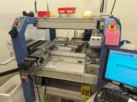
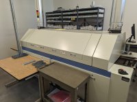
Kenzo then showed us their pick-n-place machine for stuffing SMD parts and the 'largish' soldering machine. PCBs are not fabbed at their facility, but are made in the US. He also showed us their warehouse and shipping area, where the very heavy components are boxed and crated for shipping to their dealerships. Other, less weighty items are double-boxed with uber-thick cardboard for safe shipping. As we were walking to the listening room, we got to meet and speak briefly with the owner/CEO of BA, Jeff Nelson. More about Jeff and the BA story can be found on the internet and YouTube.

Now for the most exciting part of our tour....

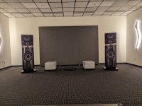
The last part of the tour, and probably the most anticipated, was getting to hear what the BA gear could dish out - specifically, the 3050 mono block amplifiers, each attached to the gorgeous Focal Grande Utopia EMs. And DISH OUT they did! The equipment used in their demo room that we listened to consisted of; their model 812 DAC/Streamer/Preamp feeding their 3010 Preamplifier with separate Power supply, feeding the 3050 mono block amps and each feeding the enormously large, Focal Grande Utopia EM in red. Just for some idea just how large these speakers are.. they stand 80" tall, 26" wide and 35" deep. Oh, and by the way, weigh in at 584 lbs each!

The listening room was about roughly 20' wide x 30' deep. Kenzo provided the exact dimensions, but I can't recall the details. The only treatments in the room were large roughly 9 x 10' cloth covered shallow panels in the middle of each wall. They took a very conservative approach with treating the room, so nothing fancy.

The moment of truth was about to be revealed as Kenzo took out his phone and fired up the first track using Roon. I believe the track was all instrumental without vocals, but can't recall the specific details. All I can remember was how it sounded. The absolutely smoothest, effortless music that has come out of any system I've heard. The precision and articulation of each and every note could not have been better. My son and I were equally amazed with the sound we were hearing. The pure sonic expression of music, as if you were seated in the middle seat of the studio, or stage. And the noise floor? Well, it simply wasn't there.

Next up was a very unique piece by Yosi Horikawa, entitled 'Bubbles'. However this piece was recorded in 2 dimensions, it sounded like bubbles bouncing and popping from wall to wall. The soundstage simply jumped off the stage, so to speak, and widened from wall to wall. You clearly heard sound outside the physical side boundaries of the speakers themselves. Impressive. 3D sound from a 2-channel. Awesome.

Kenzo handed the phone to my son and he queued the track, 'Give Life Back to Music', by Daft Punk. This track is a favorite of his and really sounded over the top with this system. Once again, the details and dynamics were so crisp and distinct. The way music should be heard and enjoyed. Next in the queue was familiar to everyone, 'Landslide', by Fleetwood Mac. This track was impressive as well, The guitar work was outstanding and the soundstage was telling. Every note plucked was clear and distinct. While not as dynamic per se, it was very well rendered on this system.

Next, I queued up a favorite of mine that I use as a reference, goto track when I audition anything I've built(or bought) - whether an amp, pre, or DAC//streamer remote for Roon. It is one of the most well-done recording in my library, short of some noted DSD tracks from Michael Jackson's Thriller album. The track is 'Walk My Way', by Beth Nielsen Chapman, from her self-titled album. This song has a lot of dynamics, done with a lot of staccato (quick end) to the notes, each note was precisely executed and positioned on the soundstage. The stereo separation was obvious, but well-balanced. At the volume we were listening at, this track brought a big smile to my face, noting how well it was reproduced, confirming my own ears when I tagged it years ago as a demo track. Even Kenzo made a note to save it in his favorites for other occasions. Oh, did I say the system we were listening to came from $410K worth of amps, and $280k worth of speakers! Not to mention their preamplifier that adds another $233K!

There had to be a end to our listening fun. I sat there in awe saying to Kenzo, that this system, "was the cleanest sounding systems I had ever heard." As well it should be. It ticked every box for what an audio system should sound like. Yeah, no kidding! At this price point, who wouldn't want to listen to it. I know one thing, my current system has a lot to aspire to! A well designed, engineered, executed and delivered - price no object - will richly reward you with the best sound your ears have ever heard.

Sadly, we had to leave, but Kenzo mentioned, that anytime I was in the area he would arrange a weekend session. I gladly accepted.

Ps. Nay sayers will baulk at the price of the system described here, and say, 'what average audio enthusiast can afford something like this'? Very few, and I would agree. But, that doesn't mean we can't afford ourselves, the opportunity when given the chance to experience the big, bold pure music that pours out of these speakers like a crystal clear Rocky Mountain stream, backed only by exacting electronics, and in the end 1500W of Pure Class A amplification through two of the well-regarded, Focal Grande Utopia EM speakers. For us, it was quick side journey to the mountain top, if only for a moment in time, to listen to sound approaching sonic nirvana.

If you ever find yourself in the Denver, contact Boulder Amplifiers and arrange a tour of their facility. I guarantee you will not regret it, and it will be of those times you think back on it with a big smile on your face.

More on Boulder Amplifiers here.

Rick
Boulder-Amplifiers-Entry-Rock-Sign-650x365.jpgPXL_20230913_185732783.jpgPXL_20230913_191115763.jpgPXL_20230913_191212684.jpgPXL_20230913_191224099.jpgPXL_20230913_191616983.jpgPXL_20230913_192419803.jpgPXL_20230913_192507126.jpgPXL_20230913_193042199.jpgPXL_20230913_193334650.jpgPXL_20230913_193538290.jpgPXL_20230913_193645390.jpgPXL_20230913_193727333.jpgPXL_20230913_193857415.MP.jpgPXL_20230913_195100357.jpgPXL_20230913_195110456.jpgPXL_20230913_195135974.jpgPXL_20230913_195519319.jpgPXL_20230913_195553697.jpgPXL_20230913_200849171.jpg
  • Like
Reactions: Bonsai and 6sX7

Free stuff, pickup in ashland, MA

Gone!

Pickup my older projects. All or nothing, some gems for the handy diyer. Make it easy for me, not a lot of questions or splitting things up, hoping to have them gone asap.

Jbl 2430h compression drivers pair. Rough shape but pass sound, aluminum phragms seem okay though, at least one core is out of spec. These were badly stored pulls from an evoi system, not the current gen stuff.

Lite dac-ah cases. 6x8.5, with nice rcore trafos. One replacement board, but probably only good for cases, conns, trafo.

Transcendant OTL-SE. may only need a retube, some hackish psu mods but the audio cct, iron etc is sll original. I have some of the tubes but others were damaged.

JBL 2404h-1 pair
Some cosmetic issues but I think they’re on-spec.

B&K 667 tube tester. Think it just “needs” an axial fuse but I have enough projects.

2x hypex smps600 v3. I think they just need new relays.

Audiosource amp a100.

Pots need a cleaning and the auto-on cct is obnoxious. Good bench amp.

That’s it! You get a load of parts at worst, I get some space. Ideally today!!

Attachments

  • IMG_1978.jpeg
    IMG_1978.jpeg
    612.1 KB · Views: 91

How to find volume resistance to be used?

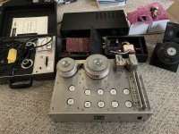
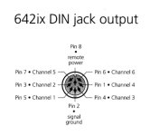
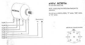
I have an electronic crossover model a/d/s/ 642ix. It has a subwoofer level adjustment feature. But, to enable this feature, it requires to use an additional potentiometer with a DIN cable connected to it. I already have the DIN cable. And I also have the wiring diagram of the pot, shown on attached. The problem is I don’t know how much resistance of the pot to be used. So I’d like to ask how can I find the pot resistance? I have a RLC meter. Also, what will happen if using the wrong pot resistance value? For example, using 10K or 100K pot in place of the correct 50K.

Attachments

  • 4180CA28-7C57-4400-9909-3007DD54CC8C.jpeg
    4180CA28-7C57-4400-9909-3007DD54CC8C.jpeg
    31.4 KB · Views: 119
  • 7BDAC6DD-AA08-41A7-B5C6-C469F27B24AF.jpeg
    7BDAC6DD-AA08-41A7-B5C6-C469F27B24AF.jpeg
    59.2 KB · Views: 120

Replacement Omron relay for a DEC DE2TU

Replacement Omron relay for a DEC DE2TU. It is for use in a Yamaha MX-1 power amp. It says 24 V DC,7A 250 VAC on the DE2TU. Here is spec sheet of the DE2TU in Japanese.

http://www.j-dec.co.jp/images/pdf/de.pdf?fbclid=IwAR0inCkK_m3DCkdfbUz_oGDpUklkmekXga_g6I31IFQa_xtgFI1hy--m-zw

Attachments

  • 131893875_10208645960981809_1593489377241110725_o.jpg
    131893875_10208645960981809_1593489377241110725_o.jpg
    481.5 KB · Views: 323

Which diy valve amp without valve sound?

Hi,

please recommend me a very good and simple to diy valve (integrated) amp with excellent sound (and preferably point to point wiring).

I am a huge Naim fan and only once tried valves: since SE triode was recommended to me as the only and real truth (I knew that such thing doesn't exist) I tried a KR audio integrated amp called VA350i with incredible big T100 valves and a very clean sound, but after 1,5 years returned to Naim, preferring even the smallest integrated to the KR: the Naim sounded dirty in comparison, but much more involving. And it never stopped annoying me that the KR made a kind of "ringing" sound, especially noticable in solo piano recordings, that sounded as if there was an empty wine glas standing somewhere on the piano and adding some strange harmonics which made the piano sound wrong, although I was really impressed how the KR removed all the fuzzyness, untidyness and smokyness I was used to. Don't get me wrong: some bigger Naim amps do sound exceptionally clear and open, but in my memory even the 500 (at that time non-DR) series sounded "dirty" in comparison to the KR...

I learned that this must be the famous valve sound so many rave about. But I thought I didn't like that ringing. Of course after I went back to Naim (now building my own clones) I missed that clear sound of the KRs and never forgot how open they sounded...

So is it possible to get all of this but without that ringing or whatever it's called?

Attachments

  • t100.jpg
    t100.jpg
    47.2 KB · Views: 151

NAD C320 fixed (another protection circuit problem)

Hi.

Finally fixed my mate's NAD C320. This had the common problem that it took ages to come out of protection (power LED stays red rather than turning green). I foiund the circuit diagram and read various similar problems here, although I replaced a few components I believe the fix was to replace C421. This connects to pin 4 of IC44 (a uPC1237, protection IC), and pin 4 is used for the AC mains detection. The design is to feed pin 4 from the mains transformer via a half wave rectifier and a resistor, the IC detects when the mains is switched off and goes into protection. Same IC is used in loads of amps, seems to be a common chip, so other amps likely to issues with the capacitor on pin 4.

Initially I though this capacitor was OK, as pin 4 originally measured about 1.5V on my DC multimeter. However as suggested on other threads I removed C421 (4.7uF 50V) and it only measured 1uF. When replaced with a new cap pin 4 measured 1.9V. However I think previously there must have been a lot of ripple on pin 4 hence the IC saw the voltage drop below threshold (0.9V) and so thought the AC was off and triggered the protection.

I also think there is some interaction on the IC between pin 4 and pin 7 (switch on delay). Pin 7 was stuck at around 200mV rather than the required 2V, so I thought originally the problem was with the associated capacitor for pin 7 (C420).

I also replaced C420 and C422 but they measured only 30% below spec and were probably OK.

Much earlier I had replaced IC44 and D412 but I don't think they were faulty.

Lesson is to think whether a DC voltage that seems OK with a multimeter could have a lot of ripple and actually fall below protection IC threshold, in which case a scope would be needed to check.

I saw on Youtube someone repaired a C320 by replacing all the caps, I think this is overkill (but would probably have saved me a lot of time!)

Regards,
John

Changing pots in tone circuit?

Hey all. New here and still learning. I was wondering if anyone could explain to me, how one could change the value of the pots used in this schematic, to 100k versions and what affect it would have on the circuit overall?

I also see some simulators available that I might be able to use to simulate this circuit? I couldn’t seem to locate any. Thanks for any help, and if anyone has some good resources anyone could recommend to learn how this circuit works would be a huge help.

Attachments

  • scheme.png
    scheme.png
    131.1 KB · Views: 128

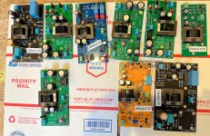
For Sale Nine Edcor PC600-15K step up transformers, soldered to PCBs, Free! You pay $17 postage

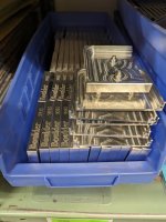
While I was developing some front end cards for the Lottery VFET amp and the (backwards compatible to Lottery VFET) Ship Of Theseus amp, I built several PCBs that were unsuccessful. Nine of these include Edcor stepup transformers which worked just fine. I'd like to get rid of the PCBs, all at once, for free. You get all nine of the PCBs, each PCB has an Edcor transformer soldered to it. You only pay the USD 17.10 charge for a USPS Priority Mail Flat Rate Medium Box within the United States. Feel free to check their website and verify the amount.

Please reply before Saturday, 23 Sept, 1AM California time. This is NOT first come, first served; everything received before the deadline has an equal chance.

If more than one member wants the nine boards-with-Edcors, I'll pick the person who asks the fewest questions and requests the fewest special favors. If there are more than one equally appealing buyers I'll resort to coin flipping.
_

Attachments

  • Edcors.jpg
    Edcors.jpg
    678 KB · Views: 490

Dynaco PAS 3X loudness switch removal

I am repairing a Dynaco PAS 3X and in addition the owner wants the volume pot replaced with a blue ALPS with no loudness switch. Removing the loudness switch looks pretty simple to me but having never seen one of these preamps before I thought I would ask about possible problems that I am not seeing.
I am planning to cut the wires to the existing loudness taps and ground connections (red lines on schematic are mine), then toss the 4.7k resistor and 0.1uF cap.
Thanks
Loudness switch.jpg

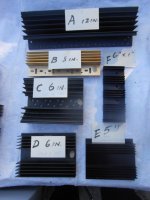
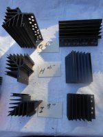
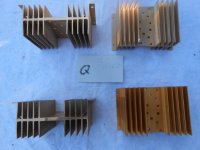
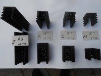
Heat Sinks for Sale

I have the following heatsinks for sale at clear out prices.
TYpeSizeFor number of TRsAvailable QuantitiesUnit Price
A12"81$15.
B8"43$10.
C6"41$6.
D6"11$6.
E5"5$5.
F6" x 1"42$5.
G6"46$8.
H4"6$6.
I3"211$5.
J6.5"423$7.
K4"214$5.
L3"215$4.
M2"116$3.
N3"218$5.
O3"22$4.
P3"230$4.
Q3"24$5
Prices in Canadian dollars
S/H extra. Please give me your full address and phone number to get the quote.
Payment by E-transfer in Canada. International payment with PayPal.

Attachments

  • DSCN0013.JPG
    DSCN0013.JPG
    256.2 KB · Views: 90
  • DSCN0014.JPG
    DSCN0014.JPG
    260.8 KB · Views: 96
  • DSCN0016.JPG
    DSCN0016.JPG
    277.7 KB · Views: 91
  • DSCN0017.JPG
    DSCN0017.JPG
    334.4 KB · Views: 81
  • DSCN0019.JPG
    DSCN0019.JPG
    189.3 KB · Views: 94

Extending Life Expectancy of Power Amp Tubes like EL34 by which kind of Switch-On Variants - which one is most useful ?

Until now I have found the following switch-on variants in commercial tube pre-/power-amplifier devices:

1) Separate switching on of heating and anode voltage (in case of present electronic control units, the anode voltage is switched on approximately 5-10 minutes later than the heating voltage - this is from my view no real soft start)

2) Regulated DC voltage for the heating rail with integrated soft start function - go to
https://tubeland.eu/index.php/bausaetze/6-dc-heizung-1-2-13v-max-2a.html
Gerhard Haas (experience electronic) basically implemented it in various of his models

3) Simple series resistor in the heating rail, which is shorted manually by switch or electronically after a certain time (but the question arises here as to which voltage on the heating filaments is ideal for warming up)

4) Soft start in the 230VAC supply (this I know only in amplifier devices like e.g. Krell KSA250 as inrush current limiter, where the toroidal transformer has an extremely small DC resistance on the primary winding and blow away the house fuse when switched on without an additional soft start unit - thus I doubt the benefit in terms of extending the lifespan for audio tubes).

Some guys claim, that even the versions from 1) to 3) has no real influence on the life expectancy of any tube and that such steps can be completely dispensed with (but this confuses me, because the cold (on-) resistance of the heating coil is significantly smaller than the resistance at operating temperature in the glowing state and therefore also the inrush current is correspondingly high).

Thank you very much for information and calling URL's to specialist articles or corresponding specialist essays (e.g. from Tube CAD).

P.S.: I started this thread after a friend who uses the Compact 100 from VTL (at whole 8x EL34 for power stages) was recommended by a modification/refurbishing center to retrofit a warm-up device to significantly extend the lifespan of these power amplifier tubes.

PS-II: Here I compile the URL's of the most interesting articles and descriptions posted during this thread:

Extend the useful life of those precious tubes: use a Tube Amplifier High-Voltage Delay
https://audioxpress.com/article/how...tubes-use-a-tube-amplifier-high-voltage-delay
https://audioxpress.com/files/attachment/2696
https://audioxpress.com/files/attachment/2694
Techniques To Maximize Power Tube Life
http://tronola.com/html/maximize_tube_life.html
http://tronola.com/Gillespie2544.pdf
The Internal Life of Vacuum Tubes
https://audioxpress.com/article/the-internal-life-of-vacuum-tubes
High Voltage DC Time Delay Copyright © 2015 - Rod Elliott
https://sound-au.com/valves/ht-delay.html
Consequences of heater standby voltage of 4V5
https://www.tubecad.com/october2000/page17.html
Getting the most out of VACUUM TUBES, by Robert B.Tomer, published in 1960
http://www.tubebooks.org/Books/Atwood/Tomer 1960 Getting the Most Out of Vacuum Tubes.pdf

Threads here on diyaudio:
1) Anode voltage (higher, lower and value for time delay after switch-on - maybe with inrush current limiting)
https://www.diyaudio.com/community/threads/tube-amp-high-voltage-delay.343711/
2) Heater Voltage (higher, lower, inrush current limiter)
https://www.diyaudio.com/community/threads/heater-voltage-range-hi-or-low.31770/page-2#post-7458953
3) Loss Power
https://www.diyaudio.com/community/threads/service-life-at-low-plate-current.194910/
4) Lifetime of Tubes/Valves
https://www.diyaudio.com/community/threads/lifetime-of-tubes-valves.317049/
5) Tube Design Idea (Lifespan Extension by reducing heater voltage without anode voltage)
https://www.diyaudio.com/community/threads/tube-design-idea-lifespan-extension.299785/

Topping E50

Hi all! My Topping E50 DAC is damaged. The switch chip that disconnects the op amp outputs from the TRS connector has burned out, so there will be no pop when turned on. and turning off the DAC. The photo shows a damaged chip. Damage to the microcircuit led to a short circuit in the op-amp power supplies (10/5V). I unsoldered this chip, the supply voltage for the operational amplifier appeared and the DAC started working. I shorted the inputs and outputs of the burnt microcircuit with jumpers. Everything works and sounds great. But there is a popping sound after turning off the power to the DAC. I contacted Topping to find out the name of this chip. But Topping, as always, is keeping this information secret. Therefore, I turn to my colleagues on the forum for help in determining the type of this chip.

Attachments

  • E50-1.jpg
    E50-1.jpg
    204.4 KB · Views: 216

Alpine 3558

So, trying my hand at this again. This time I think I have an advantage to having a pretty comprehensive service manual. Been trying to get this amp to work for some months now. When I got it, both LEDs were orange upon powering up. I took it apart and found it needed caps as expected. I replaced all the obvious leakers and the surrounding ones. Basically all new caps except for the ones on the RCA input board. Scrubbed the affected areas wtih alcohol and all that. Result now is I get a green status, but yellow mute LED. No speaker relays are clicking. I adjusted the rail voltage per the beginning of the service manual to within spec. I am throwing in the towel and asking for some help on what to look at next. From what I can see, the relays are not getting a ground to trigger them. Thanks for any and all help and I promised not to be like that other guy asking that never followed up with what he found wrong after being asked to check pins 1 and 2 at IC 502, lol

maybe I can learn enough to get back to the ADS units after this one.

Crossover Design Feedback please

Hello, Not sure if this is the right place to post this but I am designing a 3 way crossover for my first diy audio project.
I am completely new to this so I don't really know what I'm doing.

The drivers I'm planning on using are:

Sub: Dayton Audio SD270A-88
Mid: Dayton Audio SIG180-4
Tweeter: Dayton Audio ND16FA-4

I have come up with this design and the system curve looks reasonable to me but again I have no Idea what I'm doing so I would love some feedback!

Screenshot (76).png


Btw the way I came up with this is by using a crossover calculator online and then tweaking the values to get a better response curve

why are old school amps worth so much?

I see broken old school amps on ebay and even blown they are worth so much. I wonder why are amps from 80s and 90s so special?
I know most of them are made in USA but that should just not be the main factor. I worked for precision power here in phoenix until they got sold to MTX and ultimatly outsourced to China. When I worked for PPI most of people that assabled amps were from east asia working for minimum wage. The craftsmanship should not differ that much in this case.

So why are broken olds school amps worth more than brand new ones that are working in same power rating???

Binding post type connector with flat spade terminal?

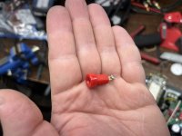
I want to replace the banana sockets on a subwoofer with binding posts, either screw-down or 5-way. The problem is, the factory posts have tab style connectors that fit into the PCB (see attached picture). Every binding post I can find on Mouser uses a screw type termination. I could always use some wire to make the connection, but it would be awesome if I could find a binding post with a tab/spade type connector that would slot right in.

Attachments

  • IMG_0336.jpg
    IMG_0336.jpg
    350.7 KB · Views: 137

Sundown SFB-8000D

Hello, I am working on this sundown amp and have it diagnosed, however, just need to order replacement parts.

Does anyone know the part numbers for the following?:


  1. Output transistors marked D1 in locations Q1-Q6, Q11-Q16, Q33,Q37,Q38,Q39 (to-247 package)
  2. Output drive buffers in locations IC11, IC12, IC13, IC14 (sot-23-6 dbv)
I don’t think these drive buffers are the uc

IMG_2324.jpeg
IMG_2289.jpeg
IMG_2281.jpeg
IMG_2276.jpeg
IMG_2277.jpeg
27511 like in the taramps though they are the same package.

Adcom GFA-555 mk1 Bypass Cap Process Check

Hello!

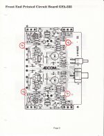
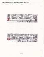
I am very grateful to this forum and have learned a lot by reading through most of the past 555 threads (even the 65+ page monster). The one mod that I am struggling to find clarity on is adding bypass caps to the driver and output boards. I understand the purpose but need confirmation on the process for this amp in particular. I have tried to dissect grainy old images and have referenced the mk2 and Hoppesbrain's work and schematics to put together what I think is correct.

If the electrical makes sense, I have a question about the mechanical process. Do I just drill small holes to pass the leads? I've not been able to find a good image of the backside of a modded board. I could run long jumpers but the photos I've seen have been much cleaner and flush to the board.

This is my first attempt at working on an amp so your confirmation is valued!

Thanks

Attachments

  • 555 input mod.jpg
    555 input mod.jpg
    660.5 KB · Views: 485
  • 555 mod schematic.jpg
    555 mod schematic.jpg
    390.5 KB · Views: 476
  • 555 output mod.jpg
    555 output mod.jpg
    544.9 KB · Views: 462

Triode conected grid resistors question

Hello. I.m at the third project using el34 triode connected. I connected both g2 and g3 directly to the plate and get stable operation and enjoy the sound. Still seeing a lot of projects using small values as 100-220 ohm resistors into the grids. I just wondering and asking why ? Did you encounter oscillations connected the grids to the plate directly at the socket ? Usually we using grid stoppers and determine its values when oscillation problems appear, Do you mount grid stoppers "just in case of" and "did not hurt" or you encounter real problems connecting directly the screens to the plates (never happen to me) please ? Thanks

Econowave style 15”

Thanks to @Patrick Bateman I’ve got a set of qsc 10”x14” 152i waveguides that I want to try in a 15” two way with these on sale faital 15fh500 woofers (ordered,should be here next week) that are supposed to be quite close to the 2226h in performance?https://faitalpro.com/en/products/LF_Loudspeakers/product_details/datasheet.php?id=151060100

I wanted these waveguides to try with the eminence N151-M https://eminence.com/products/n151m_8 after seeing this thread where PB highly regards the combination https://www.diyaudio.com/community/threads/improved-saw-lens.350889/page-2

The woofers were just too good of a deal to pass up (about half retail) so even if they don‘t work here they’ll get used somewhere.

I reckon designing a reflex box to 30 hz +/- shouldn’t be too difficult and will have to measure each driver off axis to find the best directivity match for XO …….would like to keep it 2nd order if possible (looks quite doable)

Any thoughts on this? Yes I know the XO will be right at (or below) the N151-M fs of 1.24khz but apparently its good down to 1khz or less in this waveguide. Was wondering if @Patrick Bateman would be kind enough to elaborate more on the XO used in that testing?

thanks, Bob

2 way speaker build

I am in the process of designing a 2 way speaker using a couple of pairs of drivers I have , considering a transmission line format.

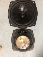
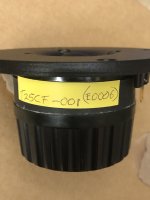
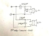
The speakers are two SEAS T25CF-001 and two old IMF mid /bass units which have a 7in cone inc rubber surround. The SES is 6 ohm and the IMF is 8 ohm looking at a crossover of 3000hz, 2nd order Linkwitz. Dont have any specs for the IMF

have attached a crossover diagram as a starting point.

would appreciate any feedback, t

Specifications

Attachments

  • imf.jpg
    imf.jpg
    391.6 KB · Views: 66
  • tweeter2.jpg
    tweeter2.jpg
    227.1 KB · Views: 63
  • crossover.jpg
    crossover.jpg
    242.8 KB · Views: 64
  • f_seas_excel_loudspeaker_tweeter_e0006_t25cf001.jpg
    f_seas_excel_loudspeaker_tweeter_e0006_t25cf001.jpg
    61.9 KB · Views: 62
  • s_seas_excel_loudspeaker_tweeter_e0006_t25cf001.jpg
    s_seas_excel_loudspeaker_tweeter_e0006_t25cf001.jpg
    39.5 KB · Views: 56

Apogee Centaur Woofer upgrade

First of all i`d like to say hello cause i`m a new member.

Second is to ask a question about the woofer`s i`d like to upgrade.
I know the questions about the Apogee`s should be in ESLs, planars, alternative technologies, BUT since i only want to ask about the woofers, i think it would be better to post here.

OK, here`s the deal.

I have gotten a set of Centaurs which where very badly abused by the former owner...so i need new ribbons and have already orderd them, thats not the issue.

What is the issue, the Vifa`s installed (P21W0-20-08) need replacing. but i dont really know with what!

I could buy the original vifa`s again, but i think there are much better woofers nowadays.

my eye has fallen on the Scan Speaks 21W8555 (dont know if the 01 is better than the 00??)

My question is: are the scan speaks a good/better replacement? i use the speakers for home cinema and am not an audiophile...so small changes will not be heard.

If i do decide to use the 21W8555, do i need to replace the X-overs? or upgrade some parts?

Info on the objects can be found here:
Apogee Centaur Website
Vifa`s P21W0-20-08 (PDF file)
Scan Speaks 21W8555-00 (PDF file)
Scan Speaks 21W8555-01 (PDF file)

Passive eliptical for tweeter, phase, physical Z offset, etc

Hi,

How about steeper slope than LR24 on a tweeter in order to use it in the octave above Fs and still protect him enough from disto, please ?

Do such filter needs offset in the cabinet like a LR2 or any trick ? How about phase with the mid with such filter an transcients ?

Also : is it possible to apply to cells ? first : a cap and a shunt coil with a ultra steep slope, then a secon seried cell with a more traditional 2 order electrical slope and still get good sounding results ?

The idea behin is to use a Seas 22 TAF/G withh a 1300 hz Fs and that has only 0.2 mm Xmax at seing te datasheet and withh an acoustical filter in the 2000 hz to 2200 hz for a MTM arrengement.

Yeah I know, not wise...

Many thanks if any idea or if you are aware about eleptical on line calculator for passive eliptical filter or the ones looking like a notch maybe in spite of ?

All drivers need to be "Burned-In", really?

Has anyone ever heard of "burning in" new speakers? Many audiophiles said the new speakers should be "burned in" for about 200 hours before their sound is stable. This is widely accepted.

But for the old drivers that have been refurbished, are they required to be "Burned-In"? This question links to my previous post that my old woofer had a new alignment—disassembled the moving parts and reassembled them at their center. And its sound was changed after the alignment. So, I wonder if they need to be "Burned-In".

Modified CD players help needed

I found a couple modified Kenwood DP-1001 CD players for sale, and am including the description of the work done on each unit below.
I would really appreciate feedback in reference to sound quality and overall improvements as a result of the upgrades. Both units are in Japan so a transformer will have to be used. Again, please, any feedback is greatly appreciated.


Modification/maintenance status, unit 1.
Cleaning the interior and exterior, disassembling the front panel and cleaning the FL display tube,
Disassemble the CD mechanism and replace the tray opening/closing belt.
For the pickup, I carefully selected one with minimal deterioration from among the many KSS-240A's I had on hand, and to improve reading performance, I replaced the capacitor in the pickup, oiled and greased the pickup assembly, and greased the loading and chucking mechanism. Replace the D/A section LPF operational amplifier with Nisshinbo Micro Devices (formerly New Japan Radio) MUSES8820, and the analog section operational amplifier with Nisshinbo Microdevices (formerly New Japan Radio) MUSES01D (installation IC socket is round pin DIP8P), CD control board. Replaced electrolytic capacitors in important parts of the main board and all electrolytic capacitors on the DAC board with audio grade products (Nichicon FG, MUSE KZ, Toshin UTSJ, Sanyo OS Con), changed the block capacitors from 3300μF x 2 to 8200μF x 2, the 7 rectifier diodes were replaced with SBDs (Schottky barrier diodes), the connection between the D/A section and the main board was changed to a MOGAMI shielded cable, and the low-pass filter capacitor was replaced with a WIMApolypropylene film capacitor (tested). The crystal oscillator is removed and connected to the TCXO unit using a high frequency cable.We added a power transformer for the operational amplifier (linked to the main power switch using a relay), installed a power supply unit that generates positive and negative voltages, and supplied ±15V to the operational amplifier on the main board and DAC board, which were modified to use a separate power supply. As for the operating condition, it has been connected to an amplifier and tested for CD and CD-R listening.The CD tray opens and closes smoothly, the CD mounts quickly, and there are no problems with all operations. There is no decrease in brightness or unevenness in the cleaned FL display tube, so I think it can be used comfortably.  
Thank you for your consideration.
Kazuki
Modification/maintenance status unit 2.
Cleaning the interior and exterior, disassembling the front panel and cleaning the FL display tube, disassembling the CD mechanism and replacing the tray opening/closing belt, and carefully selecting a pickup with minimal deterioration from among the many KSS-240A's I have on hand to improve reading performance. Therefore, I am replacing the capacitor in the pickup section.Lubricating and greasing the pickup assembly section, greasing the loading/chucking mechanism, used the Analog Devices' low-distortion, ultra-low-noise operational amplifier ADA4075-2ARZ for the D/A section LPF operational amplifier, and Burr-Brown operational amplifier for the analog section. Replaced with the OPA2604AP (OPA2604AP, an operational amplifier with a reputation for high sound quality, is unfortunately no longer manufactured by the manufacturer, and is a rare stock item) (the mounting IC socket is a round pin DIP8P), and the 4 electrolytic capacitors in the D/A section were replaced with Sanyo's OS CON's, replaced the analog section capacitor with an audio capacitor, replaced the low-pass filter capacitor with Soshin Dipped Silver Mica, and modified the master clock by removing the crystal oscillator and connecting it to the TCXO unit with a high frequency MXSU cable. As for the operating condition, it has been connected to an amplifier and tested for CD and CD-R listening.
The CD tray opens and closes smoothly, the CD mounts quickly, and there are no problems with all operations, so I think you can use it comfortably.  
Thank you for your consideration.
Kazuki

Push-pull amplifier in AB operation for EL34, 6CA7, KT77, G/FU/LS50, E/FL152, SRS552 e.g.

The two amplifier circuits from the side
https://www.jogis-roehrenbude.de/Leserbriefe/Roessler-Amp/Bauanleitung.htm
https://www.jogis-roehrenbude.de/Verstaerker/GU50-Grommes/GU50.htm
inspired me to make new layouts for it and repositioned the whole thing:
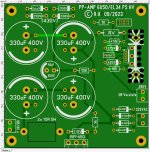
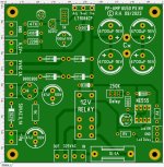
For the power amplifier drivers there is a new board 100x100mm, whereby the bases of the power amplifier tubes have to be mounted separately depending on the type used, so you are very flexible with the choice of tubes. Both 8pin octal and 9pin noval tubes can be used as driver tubes. I removed the VB408 from the power amplifier PCBs and added a replacement circuit on the power supply board. Since the circuit for both variants is almost identical, it can be used for EL34 and family and GU50 and structural body by adapting a few components.
For the power supply there is a new NV board 100x100mm with direct current heating, bias voltage and switch-on delay with relay and a new HV board 100x100mm with anode voltage and UB for the preamplifier.
VB408 replacement circuit:
https://stromrichter.org/showthread.php?tid=3116&page=4
I think this will be a project for the coming winter:snowman:

T-E.JPGPS HV.JPGPS NV.JPG

I discovered OPT's in my inventory, they have 4K but unfortunately no UL connections, ultralinear operation is also not possible!
would they possibly fit? I think I read somewhere that you can influence the impedance of the primary side by mismatching on the secondary side!?
There would also be a mains transformer with 12.6VAC 6A, ideal for 12.6V power tubes or 2x 6.3V power tubes with series heating.
50mA for -UG should be enough, right?

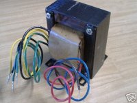
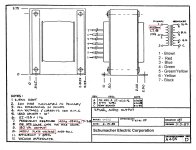
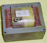
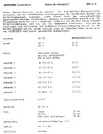
cc_1.jpgschumacher_output_trafo.JPGntr12.jpgntr_12-A.jpg

Tuner dial indicator adjustment (QUAD FM3)

Hello all.

I just acquired a Quad FM3 in good condition.

The frequency indicator is off. Before I do anything, I would like to know if there are better options than to...

1. Move indicator relative to string. There is original glue which would have to be removed and replaced.

2. Loosen screw securing pully to tuning capacitor shaft and bring indicator to correct frequency.

3. Some other method?

Performance is excellent, tuner goes over whole 88-108 MHz, so I do not want to fiddle with alignment. Is there a better way than 1. or 2. above? I have done this either 1. and 2. above succesfully in the past, on a Yamaha CT-610 II for instance. Please let me know! Cheers.

--Christian

PS I searched the forum and did not find a similar topic, forgive me if there is an older thread!

2 way speaker build

I am building a 2 way speaker using the SB SATORI TW29R-B and the SATORI MW16P-4

It sounds good. People think it sounds great, There is ample bass from the speaker. But I think there should be more treble.
the crossover is at 3Khz. Should I Lower it ? 2Khz?

Wouldn't that put more emphasis on the tweeter. I am a newbie with this stuff, And when I decided to build my own speaker I had no idea how deep and complex this stuff goes.

I also have and Usher beryllium tweeter from the tiny dancer series. I dont know what that whether that would be worth swapping out. But I like the sound. Just think it could better better

Any advice from the more advanced minds out there appreciated

cheers
thanks
  • Like
Reactions: rolf101

OPA1632D EOL

I received a notification today from DigiKey that OPA1632D is going end of life. The last buy date is in September 7 of next year, still this took me by surprise. I have ordered a quantity of these parts since I planned to use them in a future design and want to make sure I had some spares in the event of a failure. (There are six of them in my modified DCX for example)


1695051476346.png


It seems like a lot of good for audio parts are going away. I get notifications for capacitor EOL just about every week, semiconductors not so much.

Yamaha Stagepas MKII - Singer setup advice

Hi,

I'm new to this forum, so hello everyone. I'm looking for some advice please:

We have the Yamaha Stagepas 1k MKII PA system, my daughter is a singer, we play backing tracks via bluetooth using an iphone for convenience. Usually the setup sounds great. The system is loud and is just what we need for the types of venues she plays in. One thing we have noticed is that some songs make a crackling high pitch squeak almost when the there is lots going off in the song. I assume its down to the input volume being too loud from the iphone. But it only happens on certain songs. Is there a way to make sure that the input volume is consistent on all tracks, without having to manually play with the volume and EQ nobs for each song? Not sure if this is a common thing with this kind of setup. I'm rather a newbie to PA systems so any setup advice is appreciated.

Many Thanks.
Al

Audio connectors, binding posts&accessories for sale

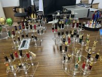
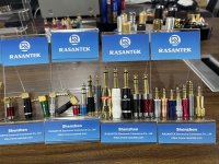
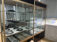
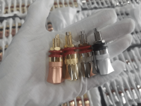
Hi Everyone, My name is Leon and I am from the Shenzhen Rasantek E-commerce Co.,Ltd China. We are the manufacturer of audio speaker connectors, cable and accessories with more than 23 years experience.
Five years ago, we start the exporting, we used to cooperated with the trading company and major in domestic market. Now in order to expand our business, let more and more people feel the Chi-Fi(Chinese Hi-Fi) power, so we are here to share our products information to you.

Attached are the pictures for your refer, here is our website: https://www.rasantek.com/

Attachments

  • IMG_2085.JPG
    IMG_2085.JPG
    738.4 KB · Views: 74
  • IMG_2086.JPG
    IMG_2086.JPG
    576.8 KB · Views: 83
  • IMG_2101.JPG
    IMG_2101.JPG
    521.1 KB · Views: 76
  • 10fa5521ea44bd01e3a7ca5aa307861.png
    10fa5521ea44bd01e3a7ca5aa307861.png
    1.7 MB · Views: 94

Fostex FE103A small footprint cabinet options

I've come across a pair of (apparently) unique FE103A and given the dedicated cabinet Fostex released for them is no longer available, is anyone aware of a suitable enclosure that can accommodate the very deep drivers?

Screenshot_2023-09-19-16-49-00-16_1883c7f851f01ba16e32f0f357d2f56b.jpg


Due to room size floor standers and horns are out of the question. The Solo-103 design for FE103 won't work with the FE103A due to clearance problems.

Screenshot_2023-09-19-16-34-11-31_57e717c094f371a1dada6567a1123b99~3.jpg


Fostex do have a simple bass reflex cabinet which might work:

https://www.fostex.jp/products/bk105wb/

However I think a cabinet like this would be doing a disservice to an Alnico driver such as the FE103A.

Reverse Engineering Emerald Physics

NC535 has a dipole thread going, and I don't want to hijack it, so I'm going to take a stab at reverse engineering the Emerald Physics 2.3 here

I've heard a few of the Emerald Physics speakers and was always pleasantly surprised

I heard the "Spatial" speakers (same engineer, Clayton Shaw) and those really blew me away.

So here goes...

To start off, i wrote this on NC535's thread:

"
Models are not 100% accurate. I am not sure what type of model is used in VituixCAD. I just use them as a rough guide, then I have to buy, build, and measure to know what is really going on.

There is a speaker by Emerald Physics that got good reviews when it was produced. You might find some inspiration in the design:
https://www.theabsolutesound.com/articles/emerald-physics-cs23-mk-ii-loudspeaker/
Some pics showing the driver layout, etc. can be found here:
https://tmraudio.com/old-products/emerald-physics-cs2-3-open-baffle-speakers-excellent-pair-cs-2-3/

To manage floor bounce I use the Allison approach: put the woofer right at floor level, as low as possible. Cross over as high as 300Hz to the midrange, which should be as high as possible (like the coax on top placement). This gives the woofer the most floor gain to the highest frequency possible, and the midrange has the least amount of floor bounce effects.

Looks like Clayton Shaw went down the same path that NC535 is going:

BNyvRih.jpg


WQecuT3.jpg


The CS2 was a fairly conventional dipole

Jne1FMY.jpg


mt4SLKM.jpg


The CS2.3 is basically a different loudspeaker. Waveguide tweeter is replaced with a high efficiency coax, and the coupling chambers on the woofers is unique

45eYZQP.jpg


u6CeIns.jpg


Their naming conventions are awful, because this is also a "CS2.3." But every last driver is different, the DSP has changed from Behringer to a miniDSP, and it introduces the triangular-ish baffle that NC535 is evaluating. In the phone online, one of them has a crack in it, and it looks like it's constructed like a surfboard, so that's new too. (Foam on the inside, wood or fiberglass on the outside, with a gel coat.)

Beveridge OTL amplifiers: Log your tube failures here

I've owned my pair for only four years but have had about 20 tube failures. Sorry to say I didn't bother to log these to see if any patterns fell out.

I can say most of my failures take out both the upper and lower tube in a totem pole. I rarely lose one tube at a time.

Also I have never had trouble in both totem poles at the same time. Failures do not cascade from one to the other.

What do you think of this for a format:

Which tube failed in totem the pole? upper/lower/both
What brand(s) of tube?
How did your fusing behave?
Did other parts fail too?

I just ate a pair of Sylvania's last night so I will reply to myself with the first data point ":^)

EAR 834 clone picking up 93.7 FM radio station

I built an EAR 834p clone a couple of years ago using a bare board from eBay and a power supply designed by one of the guys associated with the Lenco Heaven forum. It's all quality parts. I have issues with it attempting to pick up 93.7FM and I'm struggling to figure out a solution. I live up on a hill with line of sight to the 93.7 tower which is also on a hill. It's like a 100,000watt monster so I'm getting blasted. I was using interconnects with minimal shielding which clearly was adding to the problem so as a test I changed the interconnect from my Well Tempered Amadeus to Blue Jeans LC-1 since they are pretty heavily shielded and that helped. Here's what I don't understand...I'm also getting an antenna effect from the interconnects from the EAR clone TO my Sugden integrated amp. I know this is the case b/c I can move the cables around and change the radio reception issue. I can understand having the issue on the tonearm (input) side given the low nature of the source signal, the significant gain in the phono stage, etc. What I don't understand is why am I also getting a radio effect on the line level output of the phono stage but I'm not experiencing the same issue on any other source. My Qutest DAC, Sansui FM tuner, etc are all fine and using the same minimal shield interconnects. I've ordered some more LC-1s to try on the line level output side to see if that's enough to knock it out.

I don't think I have any obvious issues in the grounding or layout of the phono stage? Any thoughts on what else to try/test? It's driving me crazy.

ear.jpeg

GB Pass SONY VFET Version 2 - AL Boards by Tea-Bag

Ok, This is a summarized information for the GB of Sony Version 2 VFET boards, to build the amplifier. Somewhere along the lines Nelson dubbed it "AL" and so it is called that.

http://www.diyaudio.com/forums/pass-labs/276711-sony-vfet-amplifier-part-2-a.html#post4379458

http://www.firstwatt.com/pdf/art_sony_vfet_pt2.pdf

My blog on the Sony VFET2 is here.
http://www.diyaudio.com/forums/blogs/tea-bag/352-sony-vfet-version-2-al-boards-build-blog.html

Here is the front end. 36mm x 175mm

unnamed.jpg

unnamed.jpg


Here is the Output Stage. 54mm x 285mm
unnamed2.jpg
unnamed2.jpg


So, here is a schematic to show what is really missing here, and what is added.

AL_Nelson_mods-CB_mods_VFET-2_3.png

Recommended Parts
Here is an important piece. The boards are ideally connected via the following 2x10x2.54 headers and pins.
PN are
4 - PPPC102LJBN-RC - Digikey - S5563-ND
4 - PBC10DBAN - Digikey PN- S2111E-10-ND
Recommended
4- Front end Heatsinks - 637-10ABPE or similar
TL431ACLPR - Buy extra, if something will short, it will likely be these that die. The TL431B were found not to work well. Use "A" type.

Okay, Rundown of current pricing.
Set of boards 2x FE, 2x OS 35.00 1oz copper FE, 2oz copper OS.

B&C, Ciare, 18 Sound (and soon Eminence) in Australia/New Zealand

Was looking at the B&C website and came across the distributor for Australia.

I sent off an email and was greeted with a prompt response.
Turns out they also do 18Sound and Ciare (both owned by B&C). As Eminence will soon fall under that umbrella, I can only assume that this distributor will eventually supply Eminence.

This is great news for PA designers/ builders.

The contact is Andrew Rowan and the website is www.surgesound.com.au

I have no affiliation, relationship or kickbacks. Just thought that others might be interested.

PS.
Please save some 21SW152 for me...

Building 50W amp

Hello, I want to build some 2.1 amp around 50W per chanel. I dont have experience with building amps. I want it to be cheap (as far as possible) but to sound relatively good. I have experience with electronics so making my own board wouldn't be a problem. Please share me your makes or ideas, I will be grateful. And sorry if I made mistake in grammar, I am not a native english speaker. 🙂

Capacitance in Choke Input PS?

I'm new to this world so please bear with me.

I'm designing a choke input power supply and looking for some general guidelines on capacitance. From what I've learned with capacitor input power supplies there is guidance on the tube data sheets as to the max size of the first filter cap prior to the choke; however, I haven't been able to locate any specs for capacitors in a choke input supply.

Is there a max value for the first cap AFTER the choke?

And generally, does the community have any thoughts on capacitance in a choke input power supply? I've modeled one in PSUD and it seems to check all the boxes for a stereo 2A3 single-ended amp driven by 12AT7s. The ripple is less than 20mV at the second capacitor and the B+ is where I need it, I'm just unsure of the CRC filter after the choke.

Thanks!

Attachments

  • Screen Shot 2023-09-19 at 8.20.40 AM.png
    Screen Shot 2023-09-19 at 8.20.40 AM.png
    210.9 KB · Views: 138
  • Screen Shot 2023-09-19 at 8.19.56 AM.png
    Screen Shot 2023-09-19 at 8.19.56 AM.png
    225.1 KB · Views: 133

question for audio transformer experienced or expert

hello, I just tested output transformers 15K:150+150ohm for triode line preamplifier and this time really i need help
i frequently use for my amplifiers and preamplifiers transformers,input, interetage SE toPP, SE to SE, DC/noDC,
gapped /no gapped /bifiliar /multylayer/no DC capacitor parafeed coupling/ etc etc ,
each transformer can give good sound and linearity , i pay much attention to respect each general parameter and primary drive current and impedance, secondary load resistor, amplitude swing capacity,and so go on...
but this time i'm very upset so please help me understand if its a real bad transformer : please pay attention to
the non-standard specifications, this its a gapped E-I iron
""105H when the standard is 10 to 30H, primary DCR 1120ohm, when the standard is 100 to 200 ohm etc etc.""
cost to France 328 euro , factory description :
Wide frequency response 15K: 600 ohm tube single-ended pre-amp output transformer, boost transformer, balanced output transformer, output transformer for amp, EI76X45 iron core winding.
Primary inductance about: 105H 100Hz measurement
Secondary inductance about: 5.5H 100Hz measurement
Primary current: 35mA
Secondary current: 70mA
Primary copper resistance: 1120 ohms
Secondary Copper Resistance: 53.6 ohms + 57.7 ohms
Distributed capacitance: 16.3NF 20KHz measurement
Leakage inductance: 26.2mH 1000Hz
Frequency response: 20HZ -- 36KHZ-0.2DB
Volume: 80×68×73mm, weight about 3.16Kg/pair.
The wire package does not use the organic material nylon skeleton, and uses the original cardboard without borders. Like the Shanghai Radio 27 Factory, the output transformer process is layered with layers of paper. The superb hand-winding process ensures that the enameled wire does not collapse. The process is complicated and time-consuming. . The insulating varnish penetrates the entire wire wrap, protecting the wire wrap and the transformer core..

the problem its linearity, with DHT triode 250V30mA currently very linear with 5Kohm SE transformer,
with these 15K result very good from 20Hz to 2Khz ! but -15db @20Khz ,
and no way to get linear output, even if driven by capacitor without DC.
measurement from signal generator its perfect, sweep linear in 150+150ohm resistors.
so its a transformer for transistor preamplifier??? i do not see other way to get thems good working
of course i do not try 6C33C CF capacitor coupled.......

Attachments

  • TU HDG.png
    TU HDG.png
    121.9 KB · Views: 121

Tubes for sale

Sale:
SО-242 – 1 шт.
SО-244 – 3 шт.
SО-257 – 1 шт.
1N3S – 1 шт.
2D7S – 9 шт. в упаковке
2S4S – 1 шт.
4C14S – 10 шт.
5C3S – 116 шт.
5C3S (black plate) – 9 шт.
5C4М – 39 шт.
5C4S – 133 шт.
5C4S shaped flask – 84 шт.
6А10S – 1 шт.
6B8S – 5 шт.
6D13D – 1 шт. без упаковки
6D16D – 122 шт. без упаковки
6D16D-R – 7 шт. без упаковки
6D24N – 27 шт. в упаковке
6Е1P – 171 шт.
6Е5 – 2 шт.
6Е5S – 83 шт.
6J4P – 145 шт.
6J32P – 407 шт.
6N1P – 122 шт.
6N1P-V – 22 шт.
6N1P-Е – 10 шт.
6N1P-ЕV – 1 шт.
6N2P – 1 шт.
6N2P-ЕV – 268 шт.
6N6P – 1380 шт.
6N8M – 1 шт.
6N8S – 201 шт.
6N8S metal base – 52 шт.
6N8S metal base hole plate – 27 шт.
1578 metal base – 1 шт.
6N9М – 1 шт.
6N9S – 202 шт.
6N9S MELZ metal base – 82 шт.
6N9S Tantal metal base – 14 шт.
6N23P Voshod – 218 шт.
6N23P Raflektor – 84 шт.
6N23П-ЕV – 469 шт.
6P3S - 260 шт.
6P3S shaped flask - 2 шт.
6P3S-Е - 4 шт.
6P6S - 7 шт.
6P14P – 124 шт.
6P14P-К – 5 шт.
6P14P-ЕV – 143 шт.
6P14P-ЕR – 44 шт.
6P42S – 10 шт.
6P44S – 25 шт.
6P45S – 117 шт.
6S2S - 49 шт.
6S4S – 14 шт.
6S5S – 1 шт.
6S15P – 46 шт.
6S18S – 1 шт.
6S33S – 17 шт.
6S33S-V – 59 шт.
6S45P-Е – 158 шт.
6F3P - 198 шт.
6F6М1 – 3 шт.
6F6S – 2 шт.
10J12S – 1 шт.
10P12S – 7 шт.
30P1S – 10 шт.
30C6S – 47 шт.
GI7BT — 25 шт.
GM70 – 61 шт.
GMI-6 – 66 шт.
GMI7-1 – 11 шт.
GMI-26B – 1 шт.
GMI-30 — 40 шт.
GMI-32B-1 – 3 шт.
GMI-38 – 30 шт.
GMI-42B – 21 шт.
GU4 — 25 шт.
GU13 — 18 шт.
GS35B – 17 шт.
GU33B – 13 шт.
GU43B-1 – 8 шт.
GU46 – 25 шт.
Projects by fanatics, for fanatics
Get answers and advice for everyone wanting to learn the art of audio.
Join the Community
507,636
Members
7,881,501
Messages

Filter

Forum Statistics

Threads
405,924
Messages
7,881,501
Members
507,636
Latest member
tom.mccann