I'm new to this world so please bear with me.
I'm designing a choke input power supply and looking for some general guidelines on capacitance. From what I've learned with capacitor input power supplies there is guidance on the tube data sheets as to the max size of the first filter cap prior to the choke; however, I haven't been able to locate any specs for capacitors in a choke input supply.
Is there a max value for the first cap AFTER the choke?
And generally, does the community have any thoughts on capacitance in a choke input power supply? I've modeled one in PSUD and it seems to check all the boxes for a stereo 2A3 single-ended amp driven by 12AT7s. The ripple is less than 20mV at the second capacitor and the B+ is where I need it, I'm just unsure of the CRC filter after the choke.
Thanks!
Attachments
One thing to be aware of is the resonant frequency of an LC filter - this will of course be below the mains ripple frequency, ie below 100 or 120Hz, but is it below the lowest load frequency? If not you may get unwanted resonance effects on bass notes. Clearly you can damp the LC using a following RC, or lower the resonant frequency more, in an effort to remove the problem. There's probably some good rule of thumb for this that someone will know.
There's clearly some compromize between sensible component values, low ripple, low resonance (critically damped?), low loss (in the R or L), max load current etc.
If simulating I'd suggest trying a simulated load current sweeping between 10Hz and twice the mains frequency to catch any resonances, and possibly some step changes in load current too.

With tube rectifiers power supply caps size does matter. Even with choke input supplies the repetative peak plate current must not be exceeded. So you can use a bigger cap after the choke due there being less charging current but that also depends on the value of your choke.look up morgan jones book on building valve amps he goes into power supplies in great detail.
Thanks for the reply! Curious to know if you have experience with PSUD and if this is possible with the software.If simulating I'd suggest trying a simulated load current sweeping between 10Hz and twice the mains frequency to catch any resonances, and possibly some step changes in load current too.
And is there a way to determine resonant frequency in an LC as well as the lowest load frequency?One thing to be aware of is the resonant frequency of an LC filter - this will of course be below the mains ripple frequency, ie below 100 or 120Hz, but is it below the lowest load frequency? If not you may get unwanted resonance effects on bass notes. Clearly you can damp the LC using a following RC, or lower the resonant frequency more, in an effort to remove the problem. There's probably some good rule of thumb for this that someone will know.
Will do! My choke is pretty substantial 15H and 200mA (240mA max). Amazing how much info there is on cap input filters and how hard it is to come by choke input info.look up morgan jones book on building valve amps he goes into power supplies in great detail.
Choke input power supplies were invented way before simulation programmes and they work fine.youe have to follow the laws of power supply design obviously. Build it test it use it .
Choke input supplies do have a limitation on capacitor size during startup. As (all of) the capacitors are being ramped up from zero volts to what's often the highest DC voltage that they'll see, rectifiers should not have their space charge approaching depletion too closely (it cannot be exceeded). Modern semicons are pretty rugged, and high vacuum rectifiers are semi-rugged, but Mercury vapor or other gas rectifiers (often used with choke input) can be damaged. Some sort of slow start, like series'd damper diodes, is recommended.
All good fortune,
Chris
All good fortune,
Chris
You can use PSUD2 to indicate if the valve rectifier is being stressed beyond its transient hot-start peak current limit (3.7A), and its continuous peak current limit (825mA), for the 5AR4. Firstly, did you measure the parameter values used in the PSUD2 screengrab - such as the 'effective' transformer secondary winding resistance, and the choke DCR, and the capacitor ESR's ? For a hot start simulation, change the PSUD2 option to NO soft start, and perhaps use a load resistance (rather than a constant current) that equates to your aimed B+ and idle load.
PSUD2 can also indicate what LC damped response occurs for a step in load current. I can suggest changing the load value from the target idle current, to something near max current (you may not know this, or you may be using a class A amp in which case this scenario is a red herring), and then do a reverse step, and look at the B+ voltage response at the time of the step to see if it is well damped for both rise and fall steps,
PSUD2 can be used to indicate the ripple current in the first filter capacitor, and then to compare that to the capacitor ripple current rating - always worth doing imho for the first filter cap (whether for capacitor or choke input).
If you are using a valve rectifier then I'd recommend adding 2x 1N4007 in series with each 5AR4 anode, to minimise PIV stress on the 5AR4 anodes and avoid collateral damage if the 5AR4 thinks about arcing some time in the future.
If you were to use ss diode rectification for choke input filtering then a small noise suppression cap before the choke may be a benefit, so as to route noise current back to the transformer winding as conveniently as practical.
Some of my choke input filters have the following parts:
350V-0-350V secondary - used in a full wave rectification circuit
Two solid state diodes (need at least 1500 Peak Inverse Volt rating)
5H 200mA choke
200uF first capacitor
100 Ohms to the 2nd capacitor
200uF 2nd capacitor - This is B+ for the output tube
1k Ohms to the 3rd capacitor
200uF 3rd capacitor - This is B+ for the input/driver tube
The main resonance of the 5H and 200uF is:
1/(2 x pi x (root of LxC)) = 5Hz
The closest things I can think of to 5Hz are:
Power Mains Line Voltage [load] Bounce
3Hz record warp frequency
6Hz canon in the definitive Telarc recording of the 1812 Overture
There are not too many more load frequencies on the B+ that are at or near 5Hz.
Your choke input filter may/will need different parts values.
I do not use PSUD software, or any simulation software.
Last edited:
Choke input supplies do have a limitation on capacitor size during startup. As (all of) the capacitors are being ramped up from zero volts to what's often the highest DC voltage that they'll see, rectifiers should not have their space charge approaching depletion too closely (it cannot be exceeded). Modern semicons are pretty rugged, and high vacuum rectifiers are semi-rugged, but Mercury vapor or other gas rectifiers (often used with choke input) can be damaged. Some sort of slow start, like series'd damper diodes, is recommended.
All good fortune,
Chris
+1
I've done choke input filters with high value capacitors, such as 1800-4700uF. Slow start or additional Rdc to limit unrush currents are mandatory. That criteria should be the primary limitation.
dhtrob discusses how to build a psu with the aid of PSUD:
https://www.dhtrob.com/overige/pdf/dhtrob_psu.pdf
It is a cap input supply, but some of it may be useful for a choke input supply as well.
https://www.dhtrob.com/overige/pdf/dhtrob_psu.pdf
It is a cap input supply, but some of it may be useful for a choke input supply as well.
emtor, I'd suggest that article has two inappropriate ideas. The first relates to trying to minimise apparent ringing during hot start conditions, and the second relates to applying a snubber cap from plate-to-plate.
Start by taking everything with a grain of salt . . .
Unless your doctor has you on a salt free diet.
Your Mileage May Vary
Your Heart Beat Rate May Vary
Unless your doctor has you on a salt free diet.
Your Mileage May Vary
Your Heart Beat Rate May Vary
PSUD2 is a good way to see the effects of first capacitor in choke input supply, including oscillation in choke-capacitor resonant tank. At some capacitance value, the oscillation becomes critically damped. Jim Hagerman used to offer a calculator for critical capacitor size, but now his web site is gone. As far as I remember, the critical capacitor size for a typical tube power supply is pretty big, hundreds of microfarads.
Also, one should be aware of a huge start-up voltage spike in a choke input supply, to which tube rectifiers, but not SS diodes, are largely immune, Need some kind of snubber with SS rectifiers - a small capacitor or a varistor.
Also, one should be aware of a huge start-up voltage spike in a choke input supply, to which tube rectifiers, but not SS diodes, are largely immune, Need some kind of snubber with SS rectifiers - a small capacitor or a varistor.
Vacum tube rectifiers are also immune to electromagnetic shoch waves generated by atomic bombs.way cool.ss is not.
Again,
1. Main Resonance of a 5H choke followed by 200uF is 5Hz.
But . . .
2. You also need to worry about the resonance of the power transformer's primary-to-secondary leakage inductance, which will resonate with the power transformers secondary distributed capacitance.
That is much a Much Higher Resonance Frequency.
Perhaps this is what some of you have observed, some high frequency ringing . . . Right?
Perhaps this is why some people recommend snubbers, etc.
3. PSUD and similar software "solutions"
The leakage inductance and distributed capacitance factors are Neither calculated Nor even taken under consideration in PSUD . . . Right?
Everything is what it seems to be, until you find out it is different
Have Fun Measuring and Discovering!
Just for Solid State fans . . .
The susceptibility of solid state devices to nuclear radiation is largely determined by whether it uses Majority carriers or Minority carriers.
The NPN and PNP devices are More susceptible Versus the N-JFET and P-JFET.
Last edited:
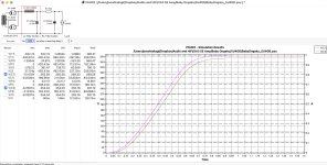
I used the manufacturer's specs for the PT and choke. The capacitor ESRs were rough calculations from figures on the datasheets for the Unicon electrolytic I intend to use. I found it easy to calculate the current draw so I went with it... for the load resistance I have 2.4k (350V/146mA=2.4k) and the results are similar. Is there a benefit to running PSUD with the load resistance as opposed to constant current? I ran it without soft start (see attached).Firstly, did you measure the parameter values used in the PSUD2 screengrab - such as the 'effective' transformer secondary winding resistance, and the choke DCR, and the capacitor ESR's ? For a hot start simulation, change the PSUD2 option to NO soft start, and perhaps use a load resistance (rather than a constant current) that equates to your aimed B+ and idle load.
This is a great real-world example. Thank you for this.350V-0-350V secondary - used in a full wave rectification circuit
Two solid state diodes (need at least 1500 Peak Inverse Volt rating)
5H 200mA choke
200uF first capacitor
100 Ohms to the 2nd capacitor
200uF 2nd capacitor - This is B+ for the output tube
1k Ohms to the 3rd capacitor
200uF 3rd capacitor - This is B+ for the input/driver tube
The main resonance of the 5H and 200uF is:
1/(2 x pi x (root of LxC)) = 5Hz
The closest things I can think of to 5Hz are:
Power Mains Line Voltage [load] Bounce
3Hz record warp frequency
6Hz canon in the definitive Telarc recording of the 1812 Overture
There are not too many more load frequencies on the B+ that are at or near 5Hz.
From what I understand the 5AR4 has a bit of a soft start. I'll explore placing diodes on the anodes of the rectifier. I also intend to use a thermistor at the input. Hopefully, this will combine to limit the inrush current.Slow start or additional Rdc to limit unrush currents are mandatory. That criteria should be the primary limitation.
Haven't messed with it but the Hagerman site was cached and the calculators all work via the Wayback Machine: https://web.archive.org/web/20060106000537/http://www.hagtech.com/theory.htmlJim Hagerman used to offer a calculator for critical capacitor size, but now his web site is gone. As far as I remember, the critical capacitor size for a typical tube power supply is pretty big, hundreds of microfarads.
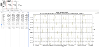
Entered my parameters (350V B+, 146mA current draw, 15H/130 Ohm choke, 220uF first cap), but wonder where and how the ripple is measured.
Did you use the PSUD2 internal calculator for the effective secondary winding resistance of 140.5 ohm ?
Is 147mA your idle loading at 354V ?
If you do a stepped load current from 147 to say 247mA, the responses show no sign of any resonance.
The ripple current of 21mA into the first filter cap is likely benign for the cap you are using.
The continuous peak diode current of 0.18A is well below rated. The hot turn-on peak of nearly 1A is also well below rated.
Why do you think you have an inrush concern that needs a solution ?
i used the internal calculator. the specs are 53.1 ohm on the 420v secondary tap. i added 10% to get my off load voltage of 462v. i don’t have the winding resistance for the 120v primary…Did you use the PSUD2 internal calculator for the effective secondary winding resistance of 140.5 ohm ?
the 147mA is the two 2a3s and the two 12at7 driver tubes. i’m looking for around 350V B+.Is 147mA your idle loading at 354V ?
belt and suspenders i guess!Why do you think you have an inrush concern that needs a solution ?
i wonder were you can find swinging choke, nowere available, only filter choke
standard filter choke will saturate and vibrate
i use to built swing choke from large filter choke,
X3/4 larger gap and stop noise by potting with resine polyestere
standard filter choke will saturate and vibrate
i use to built swing choke from large filter choke,
X3/4 larger gap and stop noise by potting with resine polyestere
- Home
- Amplifiers
- Tubes / Valves
- Capacitance in Choke Input PS?