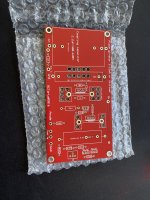
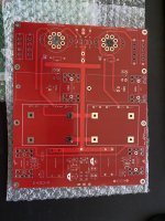
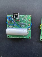
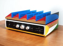
Amp I designed in the mental hospital, help me make it better

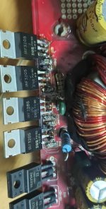
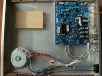
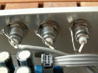
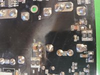
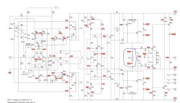
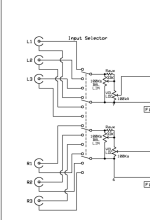
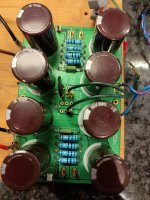
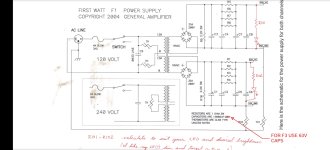
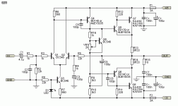
I desinged this amp while locked up in colony farm. I really want to make it better as the test I ran on it showed great sound until the mossfets I was using over heated.
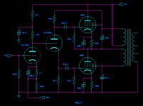
I have no idea about getting impedence right or any of that fancy math ****. I saw a diagram for a A/B class amp built one and it sounded like **** and quickly cooked out my PNPs.
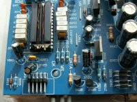
So i took the circuit and a TL082 opamp to invert one side and give noninverted the same gain and ripped some fets out of some scrap electronics.
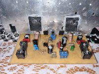
I got a great sounding amp for the first song by the end it was overheating and my fets where going into thermal runaway.

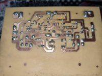
I have also fed this circuit a fixed frequency and used it as an inverter to create AC voltage out of my dc power supply.
What id like to do is somehow get some feedback resistors to the output. (Im thinking i can slow down how fast the output voltage picks up and get a more analog like sound out of it)

IMG_20231104_154719672.jpg

Help with a TQWT Sub

This YT video popped up on my feed because of my interest in Karlson type speakers. The sub in the video intrigues me. The video describes the sub as "Peerless SLS 10" in TQWT enclosure".

Login to view embedded media

I would think that the design could be reverse engineered from the visual and the driver specs. Anyone interested in posting some ideas for dimensions and possibly a frequency response sim? I think it is a little beyond my capabilities to do it for myself.

Replacement Input Selector Switch Help

I have an old Yamaha RX300 which will go quiet and crackly in the left channel, this happens in all inputs but is fine when you select tape monitor. I think it is a tired old input selector switch which I have managed to remove from the amp but I am struggling to find a replacement. The casing indicates it is an ALPS model KA502008.

Any advice on where I might find a replacement would be appreciated, failing a drop in replacement is there anything else you might suggest.

PXL_20230211_074304012.jpg

PXL_20230211_074257127.jpg

PXL_20230211_074310562.jpg

Passive Radiator Placement

HI, After an extensive research i was unable to find an answer about the placement of passive radiators when i in this case have 2 passive radiators. i am unsure about the acoustical properties if i where to mount one on each side of the enclosure or both on the back like an examble the march audio sointuva speakers. bracing the enclosure is way harder with them mounted on the sides, although vibrations from each passive radiator will cancel out eachother. mounting them on the back i would imagine making a rocking movement when playing loud or very low frequencies. in my case i got a purifi extended woofer and a sb acoustic tweeter together with 2x passive radiators from purifi and i would make an enclosure around 16L of internal volume. the placement of the enclosure is going to be very close to the back wall
I am asking the forum for some help and guidance in choosing the placement, hopefully people have some good suggestions
Kind Regards - Marcus Helweg from Denmark

Searching B9D magnoval high quality sockets for EL519/EL509/6P45S

Hello

I have two Melos SE75 mono blocks which have bad output tube sockets. I always had to clean, tighten pins, squeeze tubes to get good contact. I'm really tired so I want to change the 8 sockets with the BEST. There's a lot of Chinese sockets but... I found these which look great with thick metal pins. I need PCB sockets but I can fit std sockets with fiddling.
https://retrostore.eu/en/d/patica-elektronky-9-pin-magnoval-b9d-do-dps-1000559/
Any recommendations ?
Thanks

Mark Levinson JC-1DC

Recently was cleaning out my father in-laws basement and found a Mark Levinson JC-1DC Moving Coil Cartridge Preamplifier (Serial# 0063) that he had. Found this forum based on searching the web and was hoping that someone here could give me more info on it. Don't believe I have the equipment to test it, but based on putting batteries in it and connecting a couple speakers to the output jacks, it seems to work. Does look like the battery holder may have been replaced at some point or re-soldered. Is it worth anything, and if so, what would be a reasonable amount I could get for it, since I really can't fully test it?

Really appreciate any help!

An externally hosted image should be here but it was not working when we last tested it.

An externally hosted image should be here but it was not working when we last tested it.

An externally hosted image should be here but it was not working when we last tested it.

Building USB I2S Converter For TDA1541 DAC

Hi, I need some help with a project please. I ask in advance to forgive my general level of ignorance!

I have a DIY TDA1541 DAC, built by someone for me some years ago. The source is a modified CD player sending an I2S signal to the DAC. I now want to move to computer based audio system and have decided on using an Amanero USB board to build a converter for the DAC. I've asked a local electrical engineer to build it for me as I'm not able to do it myself, but he and I are confused as the I2S output from the Amanero board uses 5 separate connections while the I2S input on the DAC has only 3. Are the 2 incompatible or is there a solution? Is there another simpler/better solution?

I've added some photos to help.

Much Appreciated
Matt

Attachments

  • PICT0115.jpg
    PICT0115.jpg
    501.7 KB · Views: 982
  • PICT0132.jpg
    PICT0132.jpg
    351.3 KB · Views: 774
  • PICT0134.jpg
    PICT0134.jpg
    565.4 KB · Views: 838

Rockford R600X5 help

I came into repairing a rockford r600x5. There are two spots that blew bad enough to leave marks on the heatsink and blow part of the trace up. However, I do not know the values for the parts that blew. On the bOttom it is D14 and D15. I'm guessing that's d for diode. I can't get the schematic from rockford. I've found cracked solder joints on the preamp board connections.

Anyone can help me out on the diode values that went in these spots, please help.

Attachments

  • 20210814_230013.jpg
    20210814_230013.jpg
    961.9 KB · Views: 207

Sanding Laminates (KEF 104.2)

I've recently come to own an old pair of KEF 104.2 loudspeakers that need some TLC in order to restore them to their former glory. I've done the tweeter ferrofluid, foam donuts and have looked into renewing the caps' on the crossover - all steps that appear to be inevitable with this speaker system.

It's the cabinets that I wish to tackle next. Who ever owned them before me was anything but careful with what he set atop the speakers, and as such, there are a lot of very shallow but noticeable scratches as well as a few small bubbles (see attached pic') that I'd like to get rid of.

My question is; can one lightly sand laminate in order to accomplish this task?

I'm guessing that the bubbles need to be lanced and a drop or two of crazy-glue or such thin adhesive needs to be dropped into the lancing hole, then the laminate area needs to be heavily weighted for 24 hours or so (?).

None of the laminate has delaminated, and as such, I cannot tell how thick the laminate actually is... Does anyone out there think that if I used a very fine sandpaper, maybe 400 to 600 grit, that I could evenly sand the entire surface, then buff and oil the top of the cabinet back to looking good?

Appreciate your time and input.

Andrew Drouin

Attachments

  • scratched and bubbled laminate.jpg
    scratched and bubbled laminate.jpg
    899 KB · Views: 127

P-Audio BM15CX38 (What to do?)

P.Audio Coaxial Speakers - P.Audio BM15CX38 coaxial 15" speaker - P.Audio BM15CX38 500 watt 15" coaxial speaker for all full range applications. P.Audio BM15CX38 15" coaxial and other P.Audio coaxial speakers here.
This site has most of the information on this Coax driver.

I don't know if I want to build a Bass reflex or open baffle.
I know that I do not want any supplementary woofers though.
I was thinking of making the open baffles out of bamboo plywood or the Bass relflex out of Baltic birch plywood or MDF.
I want to have two of these drivers on each speaker. Two pairs total.
What crossover frequency should I use for the compression tweeter?
I am going to wire the woofer full range as recommended.
What will the ohms be once I wire the two woofers and two tweeters in parallel?
I am new to diy audio and I want to do this right if I am going to do it.
Should I use a ready made high pass crossover from Parts express?
I have been told that Open baffle speakers have a sense of realism and space that BR cannot match. Is this true? I know the bass is weak but can't I add a good subwoofer?
I am also open to using an audio nirvana super 15 cast frame speaker. What do you think?
I also heard that an open baffle needs to be 2.2 times the width of the driver which would be 33 inches.
Any help you could give would be greatly appreciated.

Topping DM7 not powering on

After being off for several days, my Topping DM7 doesn't power on anymore.
It looks like the main power module doesn't work anymore, but hard to say.
I want to open it up to do a quick see, but I can't get it to open up!
There are two screws at the back panel, abd two at the bottom panel.
After removing the screws, the internal panel can be shifted forward and backward about half an inch, so it is loose.
From online pictures it looks there's a single internal board, plus of course the mains power module.
But I guess I need to remove the front or back panel and I can't find a way to do that.
Anybody can nhelp?

Jan

Anyone using a HP ProDesk Mini or Dell Optiplex micro for an audio source?

I'm thinking of getting either a HP Prodesk 400 Mini (G5 or G6) or a Dell Optiplex Micro (3080 or 3070). Tiny little desktop machines with 9th or 10th generation lowish power intel 'T' series CPUs and an external power brick. I'll replace the stock fan with a passive cooler, and connect a USB DAC (probably also reinstall with linux).

Just wondering if anyone has tried these and found any issues (e.g. unusual amounts of electrical noise, or buzzing PSUs etc etc)?

Thanks,
Kev

For Sale 300B tubes

Cleaning out some tubes:

1x Pair Shuguang 300B-98, practically unused, SOLD
1x Pair Electro-Harmonix 300B, russia, black, SOLD
1x piece Electro-Harmonix 300B, russia, gold, SOLD
1x Pair Genalex Gold Lion PX300B, SOLD

Will ship worldwide

Attachments

  • IMG_3481.PNG
    IMG_3481.PNG
    559.6 KB · Views: 161
  • IMG_3480.PNG
    IMG_3480.PNG
    521.7 KB · Views: 151
  • IMG_3479.PNG
    IMG_3479.PNG
    399.5 KB · Views: 149

Jeff Rowland Model 1 re-cap

Hey guys

I picked up this Jeff Rowland Model 1 about 6 months ago to drive my electrostatics and so far it's been working fine. I was curious on everyone's thoughts about doing a re-cap due to the age of this amp? The epoxy modules all seem to be working fine and are all original to my knowledge.

There isn't very many capacitors to begin with, but the 4 film caps on the output boards are looking pretty tired. Is there anything else that would be worth looking at or replacing? This amp runs very warm all the time the bias maybe should be checked as well. I currently don't have a schematic and the Jeff Rowland company doesn't have much interest in talking to me so they're not a lot of help. I really like this amp so I just want to get the most out of it.

Any advice is much appreciated!

PXL_20220610_230301624.jpg

PXL_20221103_025422587.jpg

DiyinHK DXIO MC and DXIO Isolated 768K. Amanero Clone with Accusilicon and PS. Allo Boss V1.2. Hifiberry dac 2 Pro XLR.

I sell some components that I bought for testing but finally I have not used. All are new and unused, would accept half of their selling price plus shipping. Sorry only European Union.

DiyinHK DXIO MC
DiunHK DXIO Isolated 768K.
Amanero Clone with Accusilicon and PS (I value it at 80 euros. it cost more than 200 euros, but I have not been able to test it, nor can I prove that it works beyond the tensions with correct, if it does not work correctly I can return the money)
Allo Boss V1.2
Hifiberry dac 2 Pro XLR.

Thanks
IMG20230705083115.jpg
IMG20230705083119.jpg

Estimating inductance per turn

I have finally managed to source Z11 0.35mm laminates and is about to wind an output transformer for a low power guitar amp project. I wound a few before, using repurposed power transformer laminates (0.55mm), with surprisingly good results.

To get the inductance per turn on previous cores, i would 1000 turns and measured. This is a waste of copper though, so I wonder if there is a generic rule to estimate inductance per turn for Z11 0.35mm EI laminate given the core area?

Thanks in advance,
Mike

Screen Shot 2023-02-10 at 10.49.38 PM.png

The Cast Iron Griddle Amp - a Budget Conscious Heatsink Solution

Over in the FH9HVX thread, I proposed a $10, 10lb cast iron griddle for use as a heatsink for a budget conscious amp build. I think folks were thinking that I was kidding... I know, cast iron is not very thermally conductive like aluminum or copper. However, for modest heat loads of a Class AB amp, it might be perfectly acceptable. We all know that the heatsink and chassis is one of the most expensive parts of an amplifier. The FH9HVX amp has a basic BOM that is about $32, the boards are another $40/pair. Depending on what you use for the PSU, you could use a $20 Abeltec SMPS (a buyout from years ago), or perhaps a $32 toroidal trafo and some bulk caps. But when it comes to the heatsink, a typical one from Heatsinksusa will set you back about $70 a pair, cut and shipped. Sure, they are aluminum and look like real heatsinks. But we are talking about a buget conscious amp here. One that still sounds great and can belt out 100w into 8ohms with 0.003% THD with only a pair of Fairchild FQA MOSFETs.

So I went to my local Walmart (or you can look for one at secondhand store, an Army/Navy surplus store, etc). If you can find an old cast aluminum griddle even better. This one is available from Walmart for under $10.

845079d1589781275-fh9hvx-budget-conscious-100w-class-ab-lean-times-griddle-amp-00-jpg


I had to do a little bit of sanding to get the surface smoother and more likely to transfer heat better. The drill and tap 4-40 or M3 tapped holes where you want to put the MOSFETs (I spaced them out evenly). Cast iron is very soft and drill and tap operation is like butter:
845080d1589781275-fh9hvx-budget-conscious-100w-class-ab-lean-times-griddle-amp-01-jpg


Here is a MOSFET mounted with a ceramic spacer (thermal paste will be required):
845082d1589781275-fh9hvx-budget-conscious-100w-class-ab-lean-times-griddle-amp-03-jpg


For the FH9HVX, I decided to use silicone insulators since the heat load was not that great and I think the silicone will conform to the texture of the cast iron better:
848639d1590823434-fh9hvx-budget-conscious-100w-class-ab-lean-times-griddle-fh9hvx-mosfets-install-04-jpg


I am using little helper "snubber" boards to allow remote mounting of the MOSFETs which really simplifies the installation of the amp. The boards have built-in RC "snubbers" in case we run into oscillation issues. The snubber boards help to reduce the mechanical stress on the pins and the wires. I use ultrasoft silicone insulation, supple and soft high strand count RC race car wires for the wiring harnesses between the MOSFETs and the PCB. We used Molex Minifit Jr locking connectors for the MOSFETs. This lets me remove an amp in under 2 minutes. Thi s is the N-ch with a Vbe multiplier temp compensation sensor:
848640d1590823434-fh9hvx-budget-conscious-100w-class-ab-lean-times-griddle-fh9hvx-mosfets-ch-05-jpg


Here is the P-channel mounting:
848641d1590823434-fh9hvx-budget-conscious-100w-class-ab-lean-times-griddle-fh9hvx-mosfets-ch-06-jpg


Here is the amp being tested using the griddle:
848642d1590823434-fh9hvx-budget-conscious-100w-class-ab-lean-times-griddle-fh9hvx-mosfets-setup-07-jpg


848643d1590823434-fh9hvx-budget-conscious-100w-class-ab-lean-times-griddle-fh9hvx-mosfets-setup-closeup1-08-jpg


Here is the first sound of the FH9HVX amp - all went smoothly and the amp sounds great. The amp is running +/-35v at present and 150mA current. Playing music at normal listening levels, the griddle is about 39C near the MOSFET and barely warm 5 inches away. MOSFET body temp is about 52C.
848644d1590823434-fh9hvx-budget-conscious-100w-class-ab-lean-times-griddle-fh9hvx-mosfets-setup-closeup2-09-jpg


So far this is working out real well. I will install RCA jacks and binding posts for speaker out in the horizontal "grease well" as it provides a flat bulkhead. I will install a MakerBeam frame on the back for the trafos and PSU's, and the griddle will sit up vertically rather than flat and horizontal. That should help the natural convection cooling somewhat. It mught be fun to try this on a Class A like the Alpha Nirvana.

The Griddle Amp works well for a budget heat sink solution. It is really tough to find a heatsink for a 100w+ capable Class AB amp for under $10.

Here is the completed amp:

849180d1591003996-cast-iron-griddle-amp-budget-conscious-heatsink-solution-griddle-amp-final-02-jpg


849185d1591003996-cast-iron-griddle-amp-budget-conscious-heatsink-solution-griddle-amp-final-07-jpg
  • Like
Reactions: Hipocrates

Excessive high tone pitch

Hello all, thank you for any help. I have a question. Lately I have been having excessive high pitch. I'm not sure how to describe it. I guess it would be like scratching your nails on a chalkboard sound in the background of music and movies. It just started about 2 weeks ago. And a lot of people are complaining at our movie theater about a very uncomfortable sound. I'm not sure if it's coming from a receiver, the amps or the speakers. I've never heard of anything like this. It almost sounds like a high-pitched squeal or like a ringing in your ears. I'm just curious if anybody has any experience with this with a full-blown system. I have two marantzs receivers and bunch of four channel amps and a bunch of speakers. This is a movie theater/ event location for children. I don't want to be damaging or causing discomfort to the children. I'm not sure how to track this down. I've turned off multiple amps to see if it went away and it's still there. If I pull the marantz receivers then I have no sound so I'm not sure how to test for it or to find out what's causing it. Any ideas? Thank you for any help.

Wide baffle midbass cabinet - single 12" vs dual 12"

Hi all,
Novice builder here looking to build a new wide baffle midbass cabinet for my system.
Over the years I've experimented with different horns, I prefer the big radials.
Current 4way active system contains 2 x Community Light and Sound fiberglass radial horns per side:
1" SRH w/ND350 driver (4000Hz-up)
2" BRH w/M200 driver (600Hz-4000Hz)
12" 2206H (75Hz-600Hz)
18" VBSS (down-75Hz)

The midbass cabinet with single 2206H is only 16" wide, it was originally built to compliment a much smaller horn, I now want to make it same width as 33" wide BRH.
I can buy another pair of 2206H locally for a good price.

Assuming the new cabinet is to be 33" wide... would it be best to keep the midbass as single 12" or would it be better to incorporate dual 12" instead ?

See current setup pic and drawings for new midbass concept.
Look forward to your opinions and comments.

Current 4way setup
More light.JPG


NEW Wide Baffle midbass - Single 12" vs Dual 12"
Midbass single vs dual.jpg

Unstable Bias voltage Audiolab 8000P

"fixing" a pair of Audiolab 8000P amplifiers, where the i/p phono connectors had "crumbled". Most of the Electrolytic caps were wrong, so all changed, including the 4 off 10,000uF reservoir caps (one amp was fine, the other had two failures, interestingly the ones with a slight bulge tested ok) So they sound fine to my ear. Now adjusting the Bias from around 47mV on both channels of both amplifiers back to the 22mV recommended in the service manuals. Problem is it seems to go up and down around the 22mV (from 20mV up to 24mV). Is this normal? (Finding service manuals for these is hard. I have a 8200P cct diagram which is near enough the same plus this one. Measuring across TP13+ and TP13-. Before I adjusted the Bias, the valuse were also going up and down. This is after its been on for some hours now,

Attachments

  • Audiolab8000P Bias cct diagram.JPG
    Audiolab8000P Bias cct diagram.JPG
    145.6 KB · Views: 149

Trace Elliot Acoustic Cube - Help, urgent..

I bought this amp used several years ago, and it's wonderful. However, it died on a gig last night, and I need it for another gig on Thursday. I've purchased and downloaded the service manual with the schematics, but the parts list page for the preamp stage is wrong.. it's a duplicate of the parts listing for the power output stage.

In any case, here's the symptom, and I've never had an amp do this before. I'm hoping someone can point me to where to start searching for the cause..

While playing, it started to buzz very loudly and steadily, and turning the output volume and preamp gain down all the way didn't reduce the loud steady buzzing sound at all. I powered off the amp (I use it as a right channel in a small-room keyboard rig) and continued and limped through the gig using an SWR bass amp I use for the other channel and low end. I powered up the Trace a few more times throughout the gig, hoping it had just overheated or something. Upon power up, it sounded great... for a few seconds, then the loud steady buzz started up again. I gave up.

Sooo... I'm about to open the amp up, schematics in hand, and have a good 'scope, multimeter, function generator, and good soldering skills. What I don't have is a lot of experience troubleshooting. Any help would be GREATLY appreciated.

Thank you.

For Sale OEM Proac woofers and tweeters for beginning DIYers, $80 shipped

SOLD
I have a set of OEM Proac drivers pulled from my Proac Tablette 2000 - I reused their cabinet for DIY (I know it sounds expensive but I don't have access to good cabinets).
The drivers are
SEAS 19tff1, 0.75" 8 ohm ~ $90 new
SEAS CA17 (Proac variant), 6.5" 8 ohm ~ $100 new for non-Proac variant

I will sketch the original Proac crossovers with measured values for reference. I'm basically asking for just shipping and handling here because i don't want these lovely classic drivers to sit in my closet and go to waste.

EF80/6BX6 glow on power up

I got these on ebay for an IF strip to replace 6EJ7's which had too much gain and lead to instability. They look nothing like a EF80 internally and don't look ever used. They work perfectly! Thing is when you first power them on you get an incandescent glow from the bottom of the tube which disappears about 2s as the heaters warm up. I've not seen this before is it some sort of heater protection?

https://www.worldradiohistory.com/h...less-IDX/IDX/70s/PW-1972-03-OCR-Page-0090.pdf

Attachments

  • 20231104_184609.jpg
    20231104_184609.jpg
    570.1 KB · Views: 89

For Sale Radu Tarka 01A Shiny Eyes preamp PCBs, mouser parts and 4x Cunningham CX-301A tubes

Parts for Radu Tarka 'Shiny Eyes' 01A preamp build (based on Ale Moglia Bartola Valves 01A)

Includes written instructions for build and...

1x main board
1x PSU board
2x Plate Gyrator Boards
2x Ale Moglia (Bartola Valve) pre-populated gyrator board (which may be used in substitute for the above)
1x B+ board
4xCunningham CX-301A tubes (purchased from Andy)
All PCB mounted parts, including transistors (incl. LND150 Mosfets which have long lead times) are supplied. All sourced from Mouser, but excluding caps (4x caps needed I think).

Things you will need to source to complete the build:

A chassis (or two if you want split/isolate power and output sections)
2 Coleman regulators V9
Hook up wire
Mains transformer
Some capacitors (as mentioned above)
Volume pot
... + probably some other sundries - but most of what you need is included.

Asking £300, free shipping in the UK, please ask for other destinations. Will be shipped double boxed.

Attachments

  • Example of completed build.jpg
    Example of completed build.jpg
    583.7 KB · Views: 223
  • PSU PCB.jpg
    PSU PCB.jpg
    608.9 KB · Views: 225
  • A very large amount of components from Mouser.jpg
    A very large amount of components from Mouser.jpg
    461 KB · Views: 187
  • 1x B+.jpg
    1x B+.jpg
    601.4 KB · Views: 176
  • 2x Plate gyrator follower PCB.jpg
    2x Plate gyrator follower PCB.jpg
    680.5 KB · Views: 170
  • 01A main PCB.jpg
    01A main PCB.jpg
    573.3 KB · Views: 172
  • 4x Cunningham 301A.jpg
    4x Cunningham 301A.jpg
    471.7 KB · Views: 194
  • Gyrator boards x2.jpg
    Gyrator boards x2.jpg
    712.3 KB · Views: 225

Single-stage class A 20 wRMS mosfet-amp: can you help me to develop it?

Hi,

I'm playing around the simulation of a single-stage class A mosfet amp with triode curves, an efficiency close to 50% and a Zout around 0.38 Ohm.
I've used the same concept in two stage tube amps doing what @Tubelab_com did on pentodes, but here I would like to apply to a simpler low voltage circuit.

On LTSPICE (file attached) results are very good:
  • a Zout of 0.38 Ohm (so a DF of 21)
  • 0,09% THD at 1 Wrms with 180 mVrms at its input (all harmonics fall 20 dB below the previous one)
  • 0.47% THD at 10 Wrms (all harmonics fall 8 dB below the previous one)
  • 5% THD at 20 Wrms. This is due to the error only feedback that scales down the output and subtracts the input signal to in, in order to have only the error to inject as feedback: no loss of sensitivity for the amp while increasing the DF and reducing the THD.

I would like to have suggestions from you more experienced people concerning the feasibility of the circuit and the choice of the best components for it.
Most critical parts seems to me the choke (is the Hammond 193U a good choice?) and the mosfets: the p-mosfet should be able to dissipate 10 W and each of the two n-mosfets 20 W each.

Thanks in advance for your help.

Roberto

1697150740256.png

Attachments

Rehabbing the Pioneer SX-1000TW

Hey hey, early this year I repaired my NAD C350 with a lot of help here, and today I finally started to rehab this:
PXL_20230122_193407081.jpg

It came to me from the original owner, and it works and sounds okay, but there's quite a bit of hiss when I listen through headphones, and of course the controls are very, very scratchy.
Earlier this year I went after the switches and pots with DeoxIT, and that seems an ongoing project. Every time I think I've got them, I walk away for a while, and when I return they're noisy again.
I've spent a lot of time studying the service manual from HiFi Engine, and reading threads on this and other forums. The service manual is excellent. It's so cool how open to service electronics manufacturers were in the old days. After ordering a box of electrolytics and transistors earlier this summer, I finally started today, replacing the 2SC458LG transistors and caps on the Head Amp Unit (phono/tape preamp). I'm using KSC1845FTA as a replacement transistor for those.
So far so good. I started with this section of the amp thinking it would be fun to hook up to a turntable after just this bit is done to see if I like the phono stage any better than I remember. I'm not sure what I'll do after that, but I have new filter caps (going up to 2200µF from 1000) and output coupling caps, so might do those next.
I do have a question about the noise the amp puts out, but I'll save that for later.
  • Like
Reactions: madis64

Attn. Dr. Geddes: What about acoustic lenses?

I recently did a little searching on the internet for devices that could be used to control the dispersion of HF devices, other than highly engineered horns. I came across acoustic lenses that JBL developed back in the late fifties, early sixties. They looked like louvers mounted in front of the horns. They look funny, but once I figured out how they worked, they struck me as very elegant solutions to the targeted problem. By providing ever longer pathways for sound sound emanating further away from the centerline of the horn, thus delaying its launch from the device to varying degrees, it diffracts the sound much like a glass lens diffracts light. But they only control horizontal dispersion given their 2-dimensional form.

I was blown away by this.

Seems like metal foam with open cells of the right size could be used to create acoustic lenses that could control both vertical AND horizontal dispersion. Since you use a foam plug in your horn designs, I was wondering if this approach ever occured to you and if so, what you thought about it.

KR Tubes VV 32B

I Sell a pair of brand new KR VV 32B tubes,

One with blue glass, one with standard trasparent glass.

Tubes were never used. I'd as spare tubes for my old amplifiers i sold years ago.

Price 500 Euros.

Attachments

  • IMG_20231103_224254.jpg
    IMG_20231103_224254.jpg
    423.7 KB · Views: 78
  • IMG_20231103_224323.jpg
    IMG_20231103_224323.jpg
    317.7 KB · Views: 75
  • IMG_20231103_224354.jpg
    IMG_20231103_224354.jpg
    266.8 KB · Views: 74
  • IMG_20231103_224339.jpg
    IMG_20231103_224339.jpg
    246.6 KB · Views: 78

Ditching the balance pot in Bottlehead Smash

Hi All,

I have a Bottlehead Smash that I built a few years ago. I want to remove the balance pot and instead use separate L/R volume pots. The schematic for the input/volume/balance portion of the circuit is attached. In my simplistic way of thinking, I can just take out the balance pot and wire in separate volume pots, but would 100K volume pots still be correct? And do I still need the 33K resistor? Just not fully understanding the interplay between the volume pot and balance pot.

Attachments

  • Screenshot 2023-11-01 203928.png
    Screenshot 2023-11-01 203928.png
    16.8 KB · Views: 146

For Sale Hiquphon OW1 Tweeters $80 shipped

SOLD
This is a pair that I bought from this forum about a decade ago and they are $280 new now.
I used them for a few years but have since repurposed the cabinet. Still come with original measurement graphs and original box, but one tweeter has some soldering iron marks at the back, as seen in pic.
Asking $80 due to age. Can't beat these if you need high dispersion.

Attachments

  • diyaudio1.jpeg
    diyaudio1.jpeg
    403.3 KB · Views: 121
  • Like
Reactions: Gill.T

Threshold S/500 Series ii: Class A Operation

Hi, I am trying to gauge the manner in which the Threshold S/500 operates in Class A mode given the impedance characteristics of a pair of Sound Labs.

Would someone assist with information on how the S/500 operates in Class A at an impedance other than the nominal 8 ohm rating, for instance a 1 or 2 ohm load. It seems the amplifier operates in Class A up to 20% of its nominal power rating(250 Watts into an 8 ohm load).

Apparently some if not most Class A functioning amplifiers exhibit a phenomenon called "de-rating," whereby there's a reduction in Class A power at lower impedance(Exceptions to this phenomenon comprising the likes of the Pass Aleph series and probably the Classe DR-3-VHC); and it looks like some Class A/AB amplifiers don't even operate in Class A where the load is anything lower than the nominal impedance rating.

Does the Threshold operate in Class A at impedance levels lower than 8 ohms? If it does operate in Class A at these levels, does it exhibit the de-rating phenomenon described above?

Thanks for your help.

Speaker Replacement and Crossover

Hey y'all,
I have some creative s700 speakers that need replacing. One of the surround speakers has a cut in the outer surround of the mid driver. So ive decided to open and have a look. These are 2 way speakers and have a crossover inside the box. The tweeter is rated at 4 ohms and the mid driver at 8 ohms. Im thinking of replacing both front surrounds to keep it equal sounding. Im thinking of changing the tweeters aswell.

Stock tweeter is 4 ohms and mid drive 8 ohms and then a crossover.

Im looking to replace with a 6 ohm tweeter and 4 ohm mid driver. Is this possible or i would have to change the crossover as well. Because the amp runs these at 8 ohms, so i dont wanna hookup anything less than 8 ohms and put more load on the amp.

20231102_215216.jpg

Voltage/ohms mismatch

I’m building a poweramp for my frfr guitar cabinet. I’m using the QuadCortex modeler as a preamp. Currently I’m using the Harley Benton GPA-400 as a Poweramp, but I don’t like the sound, it gets harsh as soon as you turn the volume up.
As far as I know Seymour Duncan is using Icepower modules for Powerstage amps. So I was thinking why dont I just build an Icepower 700AS1 module into my cab. One device less to drag around.
I was expecting this to be easy but the result was not what I expected. It sounded good when I had the QC volume at half, but when I turned it up the sound got all distorted and wasn’t as loud as I would expect.
The dealer explained to me that the output voltage of the QC was too high for the Icepower amp.
From the QC manual:
Analog Outputs 1-2
• Connectors: (2) XLR-M with Ground Lift
• Impedance: 560 Ω
• Max Output Level: +9.5dBu
Analog Outputs 3-4
• Connectors: (2) TRS
• Impedance: 560 Ω
• Max Output Level: +15.5dBu balanced, +9.5dBu unbalanced


“Quad Cortex 4.6V (calculated from +15.5dBu). For the 700AS1 the max is 3,3V.”
Basically I have two questions.
  • How do I fix the Voltage/ Ohms mismatch issue?
  • What would be a good 3 band eq solution to add?

Thanks!

F1 PSU rails in series ?

I have this F1 Psu, 2 single rails of 24v. Been using it to power 2 X ACA.
I wish to try my 3255 class d amp and it wants for single rail 48v or so.
Can I put the two 24v rails in series? The two grounds for the rails aren't connected. Separate windings and rectifiers.
It has 35v caps. Is that still ok or would I be putting the sum of the rail voltages thru them? If so it's a no go!

Attachments

  • IMG20231104141711.jpg
    IMG20231104141711.jpg
    489.9 KB · Views: 66
  • Screenshot_2023-11-04-14-10-06-80_f541918c7893c52dbd1ee5d319333948.jpg
    Screenshot_2023-11-04-14-10-06-80_f541918c7893c52dbd1ee5d319333948.jpg
    147.9 KB · Views: 71

Which I/O?

I'm working on a project based on a powerful SBC. I want to make a closed loop and custom make a dac and adc for it. The board itself has a lot of great I/O including 2.5Gbps ethernet, USB3, and thunderbolt 4, as well as arduino. Which would be the easiest vs most worthwhile to implement for data transmission and collection? Or would it behoove me to choose one more than another for a specific use case?

  • Locked
Advise for new speakers for my PC setup

Hello there =)

I'd love to get some buying recommendations for new speakers and thought this might be a good place to get some advise.

Currently I own a Creative Sound BlasterX Katana (v1) for my PC setup which is a soundbar with a peak output of 150W and a 75W RMS. It has two 2.5″ (63.5mm) Upfiring Midbass Drivers, 1.3″ (34mm) High-excursion Tweeters and a 5.25″ (133mm) Subwoofer Driver. I like the sound of it, it fills the room quite nicely. However I'd like to switch to a pair of speakers to get some stereo sound.

Here are my requirements/wishes:
  • They shall sit on my desk, so not tooo huge
  • They MUST be available in white in order to fit into the setup
  • Price range is about 300-500 € for both speakers
  • I was thinking about studio speakers but am unsure weather these are the right kind for me
    • I like to listen to base heavy music (techno, etc)
    • I also watch quite a lot of youtube videos with just talking.
  • Do I need a subwoofer? I guess if the speakers are large enough I should get away without using one, right? But it's also fine if I need one
Additional facts:
  • The room has about 60 m³ of volume
  • The speakers would be about 60 cm away from my ears
  • I was thinking about tilting them up to an angle to point in the direction of my ears. Is this something to invest in?
  • I like the boxy look (e.g., yamaha hs7w) and not something like the Bose Companion 50

Thank you in advance for your help!

Am I a Dinosaur?

Hello, I've been repairing amps for over 55 years now. I've seen many different brands, units, various state of dammages and self inflicted whatever. So you could say that at my age I've seen it all...
But no.
A few days ago I saw a post on these master volume pots for a Fender Twin. You know, the one with the Push-Pull switch.
A twin (combo) came to visit my bench and to my delight it's equipped with 2 orange JBL's 120. Second time in all these years that I encountered this model.
But nostalgia on the side, the volume pot had a problem. I checked the inners and found that the carbon track was broken. I happens that this potmeter is no longer available. So I have to rely on some other version but it seems to be to tall. No luck.
Until I read that article, somewhere...
It seems that CTS pots have the same pcb with various carbontracs (resistance). I had a Mesa Boogie volume pot in my collection and swapped the small pcb.
It fitted 100% and the twin has a fully working volume pot again.
Except the tap for the high pass cap is'nt there. No problem, I placed it over the in- and output of the pot.
So, to make it short (?), all you younger technicians: You are never to old to learn something new. Most of the time it's hidden some where.
Can I say that I'm a dinosaur?

Magnepan ripole or slob

Hello witches n warlocks

A seller locally is offering a pair of tympanis quite cheap. I've been curious for a while about using planer or electrostatic subwoofers. I don't need to get down to 20 hz or anything but 30ish to a 100ish.

As the timpani has two base panels for each side I'm curious what my my considerations be in arranging each in a riplole or slob config. From what I read about that design the main problem that comes to mind is the huge surface area which leads to a huge slot. The solution that comes to mind is maybe some dividers to shrink the slot into multiple chambers. The problem there of course is it will be hard to impossible to seal each chamber from the next. But maybe that won't be a make or break issue as long as the frequency ends up being usable up to about 100 Hertz.

I do have a couple of high wattage amplifiers and DSP available for subwoofers so if there is a massive peak can I just EQ it out?

On the plus side with no motor sticking out I can make the chambers quite small on either side.
I don't really know what I'm doing so this might be a bad idea based on something I haven't even considered which is why I'm posting here.
Thank you to all who contribute to the site it's a wonderful part of my life and has given me a new hobby that is wholesome and really cool

Aikido Noval Stereo vs 9 pin dual mono

Placing my order for JB's Aikido line stage 9 pin version this weekend. I would appreciate inputs on the Noval stereo pcb vs the 9 pin dual mono boards? Are dual mono's adding complexity not worth the squeeze or not a big deal? Looks like the PS-21 is suggested for the stereo Noval board. What would I use as a PS from his site for the duals? Comments on his attenuator, power 3 position switch, input selection switch boards? Transformer recommendations for either of the above from folks who've built them? Thanks

https://glass-ware.stores.turbify.net/ainost.html

https://glass-ware.stores.turbify.net/aik9pindualm.html

Best way to incorporate N identical sub-circuits in/on a larger PCB?

I have small circuit or "sub-circuit" that will be repeated several to many times as part of a larger analog active circuit that is to be implemented on a PCB. I would like to make something versatile and flexible because the overall circuit might use four or fourteen or whatever number of the sub-circuits plus a few other auxiliary signal processing circuits. I am thinking of perhaps a physical arrangement consisting of a motherboard plus edge connected daugtherboards. Or making the sub-circuits on small PCBs that can be stacked up on top of each other above places on the motherboard PCB. Once the PCB is built it would not need to be reconfigured. I am only interested in making a flexible implementation overall.

Are there any other techniques that might work well for audio?

Are there some problems with or concerns about small PCBs that stand off of the main board, e.g. regarding noise or physical staibility?

Some simple improvements to enhance the PSRR of 5mA CCS, any suggestions?

After learning Jung's paper about CCS and some discussing in this forum, I pieced together this circuit. Choosing 2cs2705 is because of its high linearity, high hfe, and low cob. Choosing crd can increase the psrr of ccs, but it needs 10v to work well will increase the voltage drop. Using LED series connection to reduce noise. Another CRD keeps the operating current of the LED constant while improving the PSRR. Any suggestions?
1690040257101.png

Proton CD Display Not Working

I have a Proton AC-300 MkII CD player purchased in 1991 and the 7 segment green LED display is not illuminating.

Similarly the Time, Track, Pause & Repeat single LEDs are not lighting up when the appropriate button is pressed. Otherwise the CD and remote control sensor (which is also on the display board) are functioning perfectly.

The LEDs are all controlled by two CD4052B differential 4-Channel multiplexers and the 5 volt power rail seems to be OK to these ICs. Does anyone have a schematic or block diagram of a Proton or similar CD player with a 7 segment LED display which I can use to fault find.

I would have thought a 7 segment display should be pretty easy to trouble shoot once you understand the how they are controlled logically.

Thanks for your help

This will be a fun build!!!

Hi Guys.

So, a follow member (Bumbledad) gifted me a new pair of Heil AMT drivers. I decided to build a pair of speakers with parts I have in the shop.

I have a pair of JBL 6x6 horns and a pair of Dayton Audio DT250P-8 Compression Driver.

I also have a pair of DynaLab V22-DR-0003 8" Paper Cone Woofer 4 Ohm that have an f3 of 25hz in a 3 cu ft box.

The CD is solid down to 600hz out to 10khz.

so I want to cross the woofer at 600hz to the CD then cross the CD at 5khz or so to the Heils. I have an active three-way crossover and a handful of amps.

Below is a link to the woofers and a picture of what I’m thinking for the cabs but with the horn above the woofer and the Heils on top like the picture.

DynaLab V22-DR-0003 8" Paper Cone Woofer 4 Ohm


IMG_3759.jpeg

IMG_3761.jpeg

Opinions on ER Audio Acorn MkII

Hi there. Ive been a member for ages but this is my first post.

Want to ask about people’s experience with ER Audio speakers. But first a bit of background…

Recently got my hands on a pair Quad ESL63 speakers. Only had a chance to run them properly last weekend, and OMG I was blown away. My other speakers are Monitor Audio PL300ii so nothing to sniff at. But the Quads besides bass kick and extension are every bit as good as and in many aspects better than my Monitor Audio speakers. I couldn’t stop listening to them I was so blown away by the music being made by these wolf in sheep’s clothing. I messed with positioning for about 10 minutes and everything just clicked. The speakers energized the room, I could play LOUD, the bass reproduction was fast, textured and detailed… I don’t need to go on about the other aspects of the sound quality of the Quads as they are well known… suffice to say I was mesmerized by the 3d imaging just hanging in the air in front of me… I suspect the speakers are a great match for my room and equipment. I have 2 amps but the one that brought them alive was the Synthesis NYC100 valve amp. It’s a beast of an amplifier, it’s like having 2 refined 100watt mono amps in one 60kg package. The grip, extension, dimension and speed of the music being played just shocked me. (I’d disagree with using low power amps with Quads, quality amp first but then quality power really makes them come alive - I know they can only handle so much power, but it’s not about having a sledge hammer to crack a nut, it’s about dynamics and speed) My room is 6m wide x 5m deep, with an opening in the back wall into the kitchen, and side wall to another room, and the speakers just energized the room to the right degree. Just synchronicity…

Anyway, getting to the point, I’m obviously falling deep for my Quads and wondering how far I can go with panel and electrostatic speakers. I’ve obviously been reading about electrostatic speakers intensely since the weekend and I’d like to try something larger without going over the top.

Quad 2905 and 2912 are on my radar, but Ive been reading about the ER Audio speakers. I’d love to hear from anyone who has a pair and has lived with them for some time, and get their impressions of the speakers and if they’re happy. Especially if they have the Acorn model.

Looking forward to hearing people’s thoughts.

Speaker porn

(References a commercial product so the mod might need to redirect this post?)

Just saw these on my IG thread and had to share

Me likey very much. Also Cute amp to match.

Collab between http://www.wiener-lautsprecher-manufaktur.com/
And
http://riokobayashi.com/

Attachments

  • IMG_8210.jpeg
    IMG_8210.jpeg
    264.7 KB · Views: 383
  • IMG_8209.jpeg
    IMG_8209.jpeg
    223.7 KB · Views: 239
  • IMG_8211.jpeg
    IMG_8211.jpeg
    161.7 KB · Views: 232

RTR BTSB Panel Mount Buffer GB

This is a Group Buy thread for a ready to run (RTR) Best Thing since Sliced Bread (BTSB) Panel Mount universal buffer. More info on this very handy and superb sounding buffer is available here.

Briefly, it is a panel mounted PCB that accepts XLR/TRS balanced input or single ended (SE) input via RCA and provides buffering and selectable gain of 0/6/14/20dB and simultaneously provides balanced output and single ended output.

There is a an auto sense switch that activates a small high quality signal relay to disconnect the RCA inputs if anything is inserted into the balanced jack (TRS or XLR) and this is to prevent overloading the buffer with signals from two parallel sources. This automagic operation is balanced input priority. That is, the single ended RCA can only operate of there is no jack inserted into the XLR/TRS jacks.

The design is by Jhofland and sounds and measures superb. The physical design is compact and uses Neutrik XLR/TRS jacks plus high quality gold plated PCB mounted RCA jacks. This allows convenient mounting to an amplifier rear panel to keep line level signals from picking up noise inside an amp chassis. It uses a 12v DCDC converter to provide dual rail +/-15v supplies so powering it is easy.

It uses state of the art OPA1656 or OPA1642 opamps for the buffer and output SE driver, and OPA1637 for the balanced output driver. The performance is superb - low THD, inaudible self noise, and sounds clean and natural. Nothing added or taken away. Having selectable gains allows it to be compatible with almost any source/amp gain combination. Having the ability to fine tune the gain to 0/6/14/20 dB makes the BTSB suitable for driving almost any amplifier. Note that the balanced output operates at +/15v rails so with balanced output, can have an output as high as 60Vpp. This means that it could drive 0dB gain amps up to 50w (if 20dB gain is enough). When used with a 6dB gain preamp this gives 26dB overall gain. A preamp capable of 2vrms should be able to hit 50w into 8ohms in a 0dB gain amp stage like an F4, etc.

1670541317038.jpeg

1670541386927.jpeg


1670542330317.jpeg


This board is actually used as the buffer in the well-reviewed LSA Warp-1 amplifier.

1670542399456.jpeg

The design was made by Jhofland and if you are familiar with his other projects, you know that they just work well and sound great.

Here is the schematic:
1670541445509.jpeg


Measured distortion and noise at 2.0Vrms output using Victors oscillator and Focusrite in loop back:
1671746046809.jpeg


The BTSB Panel Mount buffer in RTR trim just requires you to provide a 12v (about 200mA) PSU connection, and connect the outputs (JST 2 and 3 pin jacks) to your amp. You now have a clean way to connect your amp to balanced or SE sources and you can drive balanced or SE amps. A nice feature is to use the balanced to drive your amp and route the SE as a pass through to drive an external subwoofer amp or even for bi amping.

I am offering the RTR BTSB Panel Mount buffer for the price of $165 ea as a GB. After this the price will be $215. Boards will be professionally assembled with robotic pick and place using genuine components from a BOM that I carefully specify.

If you are interested, please add your name and number of units to the interest list below.

Name / Number of Units / Country
——————————————————

biasing opamps into Class-A

Hi All.
I am trying my hardest to find a good enough reason to bias an opamp like the LT1115 into class-A (according to an RIAA preamp on the LT1115 datasheet).
The distortion figures of most modern opamps are already vanishingly low. What is the advantage then of biasing these into class-A? I have tried to build a small circuit which does this using a BF245 Jfet. On my scope, I see no difference between the circuit in (2mA draw) and not in.

Can someone please help me understand..better still, are there any before after scope measurements? ALSO... lastly, does it improve the audio output significantly enough to justify adding 2 components to boas the device?
regards Robert

Yamaha RX-A380 Protection Circuit

Hello,

I have a Yamaha RX A830 in protection mode everytime I start It ! Managed to turn It on to self-diagnostic mode, showing DC PRT 2L.

According to the manual, Cause: DC output of the power amplifier is abnormal.
Supplementary information: The protection function worked due to a DC voltage appearing at the speaker terminal. A cause could be a defect in the amplifier.

I checked and I have -5V on one of the Front Right (FR) Channel, only in speakers output (others output are around a few mV, same for preamp outputs)

A friend of mine took It, cut, removed and tested the output transistors marked in green Q1052C and Q1052A. Working correctly, PNP and NPN. We tried to start the amplifier again without the transistors and still -5V at the speaker output, and circuit protection still triggers.

1694554444957.png


My guess is that the first stage of amplification might be faulty (labelled Q1038 and Q1045 if I get It right) ? Would you identify other usual suspects ?

Nothing seem burned/boiled/exploded/.... as far as I can see.

Thank you 🙂

P3A amp problem

"I have a problem with a Class AB amplifier, Rod Eliot's P3A project. I assembled the boards, but when I inject an audio signal, I noticed that the sound is coming out low and distorting at low frequencies. Does anyone have a possible solution?"

Attachments

  • 20230909_195833.jpg
    20230909_195833.jpg
    607.8 KB · Views: 423
  • 20230909_195844.jpg
    20230909_195844.jpg
    327.7 KB · Views: 436
  • p3a-f1.gif
    p3a-f1.gif
    9.6 KB · Views: 413
  • IMG-20230829-WA0219.jpg
    IMG-20230829-WA0219.jpg
    229 KB · Views: 456
  • Projeto P3A.zip
    Projeto P3A.zip
    40.8 KB · Views: 132

Looking for a schematic for the TU-8500 Preamp

Bought an assembled preamp from another forum member. One of the non-phono inputs has some issues (left channel is out, right channel level is low). I have a friend that is an electronics tech and I am going to ask him to see if he can fix it. Does anyone have a schematic?

65 views and no responses. I found one here: https://www.hifiengine.com/manual_library/elekit/tu-8500.shtml

Shiv Naimpally
Projects by fanatics, for fanatics
Get answers and advice for everyone wanting to learn the art of audio.
Join the Community
507,532
Members
7,875,803
Messages

Filter

Forum Statistics

Threads
405,669
Messages
7,875,803
Members
507,532
Latest member
DREGNO