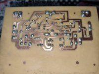
"I have a problem with a Class AB amplifier, Rod Eliot's P3A project. I assembled the boards, but when I inject an audio signal, I noticed that the sound is coming out low and distorting at low frequencies. Does anyone have a possible solution?"
Attachments
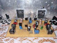
According to Rod Elliott the original designer, Q6 and Q9 should be in thermal contact, away from the main heatsink.
Make sure also that the power transistors are electrically insulated from the heatsink. Just thermal paste is not enough.
Make sure also that the power transistors are electrically insulated from the heatsink. Just thermal paste is not enough.
Last edited:

Definitely - take a look at the pics of Rod's latest version of P3A. Do you see the cable tie clamping Q6 against Q9? Most power amplifiers are actually EF (emitter follower) or QC (quasi complementary) designs which are almost always stabilised with thermal feedback from the main heatsink or directly from one of the output transistor cases. However, P3 and its versions have a different type of design that is often called a "complementary feedback pair" (CFP). Here, the driver transistors have a much better thermal characteristic to control the output stage bias current, so now the driver dissipation is the control element, not the dissipation of the output transistors.
Last edited:
Are some thermals pastes also electrically conductive?
It has probably been posted a lot of places but I think, technically, since the schematic is only supplied once boards are ordered from Rod in a secure area, that it isn't supposed to be posted online.
It has probably been posted a lot of places but I think, technically, since the schematic is only supplied once boards are ordered from Rod in a secure area, that it isn't supposed to be posted online.
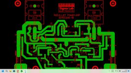
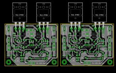
There's no harm posting schematic since it is public on Rod's site, however this PCB design is wrong or atleast not well optimized... as others already stated, you need to use insulators between outputs and heatsink... also Q5, 6, and 9 should be away from 'main' heatsink (ideally on separate small sink) or atleast Q6/9 in firm thermal contact...
Did you manage to properly Bias it? If yes, to what value?
Did you manage to properly Bias it? If yes, to what value?
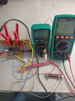
"I've discovered the issue; it was with the speaker. I replaced it with another one, and it worked well. When I inject an audio signal at around +- 25v simeter in the power supply, the amplifier functions well at low power. However, when I connect it to +- 42V with an 8-ohm load, transistors Q6, Q7, and Q8 are burning out instantly. I've temporarily kept them away from the heatsink. Some time ago, I built the same circuit on a universal perforated board using BC547 transistors instead of BC546, and it worked perfectly with 42V on a good heatsink. Does anyone have any suggestions? BC547 and BC546 transistors are quite similar."
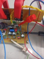
Your heatsink grease looks to have some metalic component to it.
The way its slathered everywhere it could be creating resistive or capacitive effects.
I'd suggest stripping and fully cleaning that before using a smear of normal heatsink grease.
Remember folks, the grease is there Only to fill the microscopic gaps between the surfaces.
And if your using pre-impregnated silicon pads, extra grease is Not needed or even wanted at all.
This has been a community service announcement.
You may now return to your normal activities.
😀
Since you now say the output stage only fails when you apply full power, it would seem less likely that bias regulation is the problem. However, that PCB layout is plainly wrong! It shows Q9 located next to the the heatsink panel, as P3A used to be, some years ago. This tells us that Sigma Labs (apparently the designer/supplier) didn't understand or at least test their product properly at ~20% higher than specified voltages, as you are using. The trick of locating Q9 near but not on the heatsink is an old one that seldom works properly for CFP designs anyway.
+/- 42V supply rails are also 20% higher than the recommended maximum of +/-35V (read the warning). I have also used the higher 42 voltages for P3A but it also failed on several occasions, so don't you think there's a reason for limiting the maximum recommended voltages? My latest problem incidentally, was fake power transistors from an Aliexpress store. 'nothing unusual about that by the way - some fakes don't matter much but fake power transistors really do and they are the most expensive.
+/- 42V supply rails are also 20% higher than the recommended maximum of +/-35V (read the warning). I have also used the higher 42 voltages for P3A but it also failed on several occasions, so don't you think there's a reason for limiting the maximum recommended voltages? My latest problem incidentally, was fake power transistors from an Aliexpress store. 'nothing unusual about that by the way - some fakes don't matter much but fake power transistors really do and they are the most expensive.
Last edited:
"some fakes don't matter much but fake power transistors really do and they are the most expensive."
I bought in some outputs from China.
Seemed to work ok for about 10 minutes.
I turned off my soldering iron and the glitch down the mains blew the outputs.
So bought in some transistors from RS Components and they worked well no matter how much noise I put on the mains.
I guess I could have fixed the problem with better power supply filtering.
Buy cheap, buy twice.
Dobrý den, prosím o radu a pomoc. Postavil jsem P3A a nemohu jej správně animovat. Fotky posílám v příloze. Zátěž je asi 10 ohmů. Když odpojím zátěž, LED se rozsvítí, ale DC offset stoupne téměř na záporné napájecí napětí. When I connect the load the led lights up and the DC offset drops to -1.02 Volts, I supply 20-0-20 DCVolts. Thank you for your help.
Attachments


@ mira1.
Forums rules ask that all post are in english, or have an english translation included 🙂
Forums rules ask that all post are in english, or have an english translation included 🙂
Ohh, sorry. Hello, I am asking for advice and help. I built a P3A and can't animate it properly. I am sending the photos in the attachment. The load is about 10 ohms. When I disconnect the load, the LED lights up, but the DC offset rises to almost negative supply voltage. When I connect the load, the LED lights up and the DC offset drops to -1.02V, I'm supplying 20-0-20 DCVolts. Thank you for your help.
More pictures 2.
I use a 2SA1943 and
2SC5200.
More pictures 2.
I use a 2SA1943 and
2SC5200.
- Home
- Amplifiers
- Solid State
- P3A amp problem