Looks like I made my own mistake on my homemade board. The path between the collector of Q4 and the base of Q5 is missing. After the weekend I will connect and test.
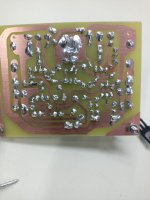
Zdravím vás všechny, po opravě chyby na DPS se mi podařilo hrát P3A. Ještě jsem neměl možnost poslouchat na Hi-Fi reproduktorech. Zvuk se zdá být dobrý, čitelný, méně basů. Na vstupu používám 10uF nepolární. Distortion can be smoothly adjusted. I'm cooling with a fan.
Attachments
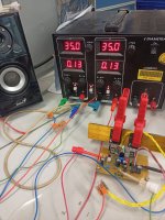
Is that Q9 which is free-floating at room temperature? If so, it would best be attached to Q5 or Q6 as already suggested and shown in Rod's pics. Otherwise, without a defined reference temperature, the bias current will be uncontrolled as the amplifier will likely now have its own, unregulated power supply. Bias current will then most likely drift towards overloading your output stage, blowing the power transistors and probably taking out the drivers too.
You may have the amplifier stable as we see the lash-up on the workbench because I guess it is only idling with a regulated supply but how well will it work at high output power, inside a case and fitted with a real heatsink as I assume you plan to, for this 60W/8R amplifier?
You may have the amplifier stable as we see the lash-up on the workbench because I guess it is only idling with a regulated supply but how well will it work at high output power, inside a case and fitted with a real heatsink as I assume you plan to, for this 60W/8R amplifier?

Hello, you are right about everything and I will definitely recommend the designer. It is not the final version. I was wondering how this amp plays. I agree with those who wrote that the middle range is beautifully readable, the vocals stand out especially during duets. The sound has its own character and plays great. I would like to thank Mr. Rodd Elliott for posting, and of course all of you for your support and motivation. I will also mention Mr. Milet Slavkovič, also for his sharing and a lot of work for us DIY audio fans.
You should give more credit to Mr Milet Slavkovic for correcting two oversights by Rod Elliot in copying a couple of resistor values from his earlier designs. I recommend that you correct your small pcb error and post an updated version of this for yourselfand for the benefit of others experiencing difficulties.
.
When setting up this amplifier fit 100 Ohm resistors in the fuse holders to ensure component safety. If a varactor is used to set rail voltages at 20-0-20, this has the effect of reducing the voltage applied to the Vas transistor which has implications for stability. This arises from the fact the collector to base capacitance has an inverse relationship with the square root of voltage seen at the collector.
Last edited: