Variac 0- 230 V;1,45 kVA ( 6,3 Amp.)

Large Variac that can handle up to 6.3 amps. In a metal housing with handle, earthed plug and socket.
I include a large panel meter (96 x 96 mm. class 1.5, soft iron) that can measure up to 250 VAC.

Furthermore, with signs of use. Has been tested and works well (except for the built-in display).

Weight including packaging is over 10 kg.

Price : EUR. 145,= + shipping

Purchase link : https://www.hood.de/i/stelltrafo-variac-0-230-v-1-45-kva-6-3-amp--116893478.htm


P_20231123_223833.jpg

Attachments

  • P_20231124_102748.jpg
    P_20231124_102748.jpg
    325.6 KB · Views: 54

Maintenance rubber surroundings Exel by SEAS W17E-002

Hi,
While cleaning out a cabinet I stumbled on the receipt of my Seas Odin speakers making me aware that next month they are eligible to celebrate there 27th birthday. It made me remember it was time for there yearly cleaning using a tiny bit of water and a tiny bit of soap. While the drivers are still performing fine I did notice that the rubber surroundings, while still flexible, feel a bit different from what I remember from years back.

So I wonder is there anything I can do to prevent further decay of the rubber? I read that some people recommend glycerol, but others believe that it only provides a temporary improvement after which the decline increases. So looking for some quality advice.

I love to keep them drivers for at least an other 10 years.

20240318_232928.jpg

Test equipment specs?

Hi all. There's a lot of posts in this forum with noobies like myself asking basic questions about test equipment. Would a sticky that outlined general recommended specs be helpful? Maybe a "Good / Better / Best" type of thing, maybe? Surely folks can understand how daunting it is selecting equipment when starting from zero? We understand it needs to be good, but how good? Not like "this cable sounds better than this cable" good, but "don't buy this function generator because the THD is too high for amplifier testing purposes" type of good.

Double bottom peak of wave forms on Rigol 1104Z Plus Oscilloscope

I'm new to using oscilloscopes and wondering why I see a double line at the bottom of the wave. It happens with my function generator connected, but also with the built in 1kHz probe tester connection on the oscilloscope. Same result with different probes in different channels, also with the same probe in different channels. Probes have been calibrated. 1x and 10x give the same result. Coupling is DC, trigger auto or manual or single all the same results as well. Please see screenshots below:

share1.png
share2.png
share3.png
share4.png

IMG Stage Line STA-1000 showing wrong operating mode on the display

I bought it for 20 euros and have recapt it because they were leakey.

when dip switch is in STEREO mode it shows BRIDGE on the display
when dip switch is in BRIDGE mode bridge it shows PARALLEL on the display
when dip switch is in PARALLEL mode its shows BRIDGE on the display

left speaker output chanel works but not right speaker output chanel when I have dip switch in stereo mode.

I think it could be some ic that is connected to the display and the dipswitch that has given up?
Anyone know what this could be?

Attachments

SH50 passive vs active

Hi all -

Continuing a discussion found both here https://www.diyaudio.com/community/threads/the-mysterious-danley-crossover.364891/ and https://www.diyaudio.com/community/...eh-synergy-project.409866/page-5#post-7631790, opening up a dedicated thread (in violation of @Patrick Bateman's first rule of Danley fight club😉) to discuss the potential sound quality benefits of an external crossover on an SH50 vs their stock passive crossover on recent models. I realize this question is probably best fit to discuss with Danley themselves (and I've asked), and I realize this isn't really "DIY", but since there seem to be a good amount of members with direct experience with the SH50, I figured there could be some nice discussion.

Overview: I'm leaning towards a Danley solution for home audio, 2 channel mainly. I've tried several other highly rated (ASR) speakers but they don't seem to be getting me closer to a "Berghain in my living room" sound that I want to achieve. So, time to try an actual PA. I like Danley because I've heard them many times in a club setting (pretty much every new club in NYC is kitted with Danley these days), and the Synergy design promises great results when it comes to side/back wall reflections. Plus, they'll hold their value much better than most small-brand hifi speakers.

My choice is now between a boxes with passive crossover, or tri-amped ones built for external crossover. I'm concerned only with sound quality, not resilience. The question: are there known shortcomings with the SH50 passive crossover such that better sound quality in some dimension can be achieved going active externally? Assumptions: I'd be running the whole thing through a MiniDSP w Dirac for holistic room correction, so presumably this would take care of in-room frequency response. What's left seems to only be phase issues on individual drivers. Are there other aspects to consider?

Given the complexities of building passive crossovers, there must be some residual tradeoffs that Danley have made for their crossovers. In experimenting with these boxes, has anyone noticed what these tradeoffs might be?
  • Like
Reactions: Speedysteve7

Kicker IQ 1000.5

I got a kicker IQ off a friend who had parked his vehicle and had to retire from driving. I had some kicker products back in the 90s so I was excited to have a what I thought was a familiar amp. And even though it was something more than I really needed I jumped through the hoops and set it all up .. sounded great until that dreaded moments of having to jump start my vehicle I used a Makita 18 volt cordless drill battery to jump my car which I had done many times before it seemed to have affected the app right away and it had overcurrent now I've taken the amp apart I am by no mean a scholar and small electronics and I'm going to hopefully be able to put some pictures in and maybe some of you much smarter men than I can let me know if you see any problems in these pictures
#1 not sure if any problem there but looked a little burnt maybe
#2 top view of the two issues I'm sure it has
#3 so okay so I'm going to sound like a kindergarten student here now but anyway I noticed the amps got like coils on one side and then the other side is there isn't any coils haha anyway there's like a fence that defines someone so I'm going to call it a fence long beside the fence is in picture number three there seems to be something that blew up and something melted I don't know what the f*** those are I'm sorry for my language but anyway I'm hoping that maybe someone could tell me what those things are and if they actually are fried blown up disintegrated melted nfg
#4 and in the fourth picture there I don't have things called now either I did remember before now I don't remember but anyway that definitely looks like it's got some melt off to the side I'm pretty sure anyway so yeah my absent protect mode it won't come out of protect mode I tried checking with a multimeter different things that were grounded and and with the you know the positive to areas it seems like the power and continuity and different spots that it shouldn't have I gather is probably more to it than I can see with my own eyes I don't know if I can get any help or even knowledge of where I should send this app Canada if anybody has any ideas thank you very much for any help
1000000304.jpg
1000000303.jpg
1000000302.jpg
1000000301.jpg

Tiniest 40hz Sub

Hello all, I have come to a point in my 2.1 project where I need to replace the current 7" driver with the smallest 40hz setup. Available power is 140wrms and there is variable bass boost

This is for very intimate night listening, so think low volume with loudness button on

Driver needs to have a mounting depth of less than 70mm. Any suggestions?
  • Like
Reactions: apaulr and Guerilla

Sansui 9090DB left channel half-wave output

Here’s an interesting one; would anyone be able to advise why this might happen?
IMG_6565.jpeg


I just repaired this Sansui 9090DB that was stuck in protection because of the amplifier card’s fuse resistors that went open. I ended up replacing all the suspect components, caps and trim pots. Also recapped the power supply, cleaned all controls and adjusted the dc offset and bias.

From a listening standpoint, the receiver works. When I went to check the channels on my dummy load however, I was presented with this nice squashed waveform on the left channel. I am not that familiar with what causes the half-wave in this situation. The only extreme thing I had to do with this one was ultrasonically-clean the volume pot assembly because the balance was nearly frozen, but I can’t imagine that had anything to do with it.

I’m going to start probing around and see if I can find where the wave starts to diminish, but I would be betting this would lie solely on the driver board / card, right? I haven’t replaced any transistors yet.

EZ81 on an 75V elevated heater supply?

So I'm developing a modified JCM800 EF80 micro amp that has a CF cathode at 190Vdc hence elevating the heaters for all tubes to +75Vdc. Rather than have HT switch straight on with solid state, I have the option of using EZ81s which would provide a nice option rather than having a HT switch. As this is more todo with amps in general, I hope you don't mine the question here.

The question is - can you use the EZ81 with elevated heater supplies?

I have a two independent supplies (hence two EZ81s) referenced to ground, the Power state HT supply provides the elevation reference. Thus it's possible for the EZ81 would need to cope with both scenarios:
A) EZ81 sees 0V HT and +75V heater
B) EZ81 sees Full HT and +75V heater

The EZ81 datasheets seems to indicate Vfk as 500V (JJ) but as k positive and f negative (Phillips). So this seems to suggest scenario A would cause a problem.

DC link capacitors in PS

I occasionally read praise for DC link capacitors in power supplies so I bought them to try. What interests me is which is the optimal position first, second or all? What are your experiences? Have you tried different brands and which one did you like best?
My amplifier is 7n7 driver and PSE 2 x 6e5p (I also have the option to put 2 x 4p1l, but I haven't used it for a long time).
Power supply is LCRCRC.

Bert regards
Slobodan

John Bowers Active One Amplifier Boards

Hi, I am in the process of rebuilding a pair of John Bowers Active Ones.
All seems fine so far, apart from a slightly high DC offset of 130mV on one of the boards.
There is no adjustment preset for DC offset, and I am wondering if anyone could advise me on the possibility of adding a DC offset adjustment preset to the Amplifier Board?
I have attached the circuit diagram. Any suggestions would be welcome.

Attachments

  • Screenshot_2024-03-07-17-41-14-15_e2d5b3f32b79de1d45acd1fad96fbb0f.jpg
    Screenshot_2024-03-07-17-41-14-15_e2d5b3f32b79de1d45acd1fad96fbb0f.jpg
    216.8 KB · Views: 285

PR'ed bandpass?

Looking for thoughts on these types of things? With a sealed cab behind the active driver and PR in front, vs PR units either side of an internal active. Merits of the active being in clamshell isobaric on the internal baffle thing? .....purpose is to maximise power density and minimise cab volume by means of isobaric and PR approaches with a helping hand to the SPL as well

Passive RIAA Equalization Calculation

Hi All,

This is want happens when I have a day off. I create an Excel spreadsheet to calculate passive RIAA equalization. I just finished putting together a PassLabs Pearl Phono pre-amp (sounds great!). But just for fun and a learning project I decided to check Wayne's work. I downloaded Stanley P. Lipshitz's AES article "On RIAA Equalization Networks" (what did we do before the WWW?)(Thank you so much Mr. Lipshitz!).

Choosing figure 7b and table 1c I created an Excel spreadsheet. Be aware, I am no Excel Wizard, nor have I taken a math class for 40 years. So I did the best I could. The spreadsheet is not elegant but it seems to work correctly.

To use it simply change the values for the Cs and Rs in yellow. The results should appear in the blue cells.

If you see any issues with the spreadsheet please let me know. Also, if you would like to add the circuit in figure 7a/table 1b, or any other circuit, feel free. I am sure other DIY Audio folks will appreciate it.

BTW, Wayne values as calculated are very close to the standard. Measured values for T5 and T0 (as calculated, but not to standard) are spot on given the standard component values he used. T4 is about 100Hz off but this may be due to component tolerances.

Thanks,
Jim

Attachments

A “Good Enough” OB/Sealed Hybrid for “Everyman”?

I know this is not a new topic but perhaps my PoV about it is different enough for this post to be of interest. Pls bear with me.

Ken Kantor’s NHT 3.3 speaker took advantage of the bass reinforcement effects of room boundaries with a low Q sealed enclosure to provide predictable deep bass extension. This large late ‘80s 4-way combined a 12” side-firing woofer positioned at the intersection of floor and front wall with an ear-height assembly of lower mid, high mid & tweeter. The 3 smaller drivers were at the top of a front baffle angled 21 degrees toward the listening area; in mirror image pairs, the woofers for a stereo pair faced each other. They had an unusual shape and size: 42" H by 7" W by 31" D. No typo -- just 7” wide but 31” deep! The angled baffle made it just wide enough to fit the 6.5” low mid driver. The narrow deep shape was deliberate. The upper frequency drivers ended up >2.5’ away from the front wall, which reduced diffraction and increased the ratio of direct-to-reflected sound. These speakers were lauded for deep articulate bass even at high levels, good imaging and neutral balance. https://www.stereophile.com/floorloudspeakers/1293nht/index.html

nht-33-audiophile-loudspeakers.jpg


I ran the smaller NHT 2.9 in my main system for some years. The woofer was a 10” instead of the 12” in the 3.3, and the cabinet was scaled down, but the other drivers were identical to the 3.3. It was not the last word in immediacy or transparency, but those aspects were decent, and the overall tonal balance when placed close to the short wall of my room (13’ x 30’) was excellent. Bass was deep and powerful if a touch heavy on some recordings, and the speakers were tonally neutral, not favoring any particular type of music. They were quite enjoyable.

The Linkwitz Orion (3.3) I built in 2014 outperformed the NHT 2.9 in every way, but this was to be expected. The Orion was active, EQ'd electronically, fully dipole, and employed drivers that cost upwards of CA$3,000 -- many times that of the components in the NHT. It was also driven with 50Wx8 rather than a 100W/ch stereo amp & needed to be further out away from the wall to do their magic.
orions.jpg


I’ve been experimenting with open baffle speakers ever since. My latest LX521-inspired speakers are likely as good as I’ll ever want. They are amazing performers that evoke “wow” from just about anyone who listens to them. But much as I love the imaging, depth & openness of open baffle speakers, their complexity, cost and positioning requirements are not for everyone. My LX521-inspired build, for example, uses drivers of ~CA$2,500 net, 8-conductors of cable to each speaker, an 8-ch Hypex NC252 amp connected with 8 signal cables to a minidsp 4x10 HD. In my audio-dedicated acoustically treated 22Wx19’D studio, they sound best nearly 5 feet from the front wall and >6’ from the side walls. Such positioning plus >CA$7,000 in components (before any source or control components) aren't feasible for a lot of folks. (Never mind the US$24,000 for a factory-built LX521 system from Linkwitz.store)

lx521.jpg

A couple of close friends have asked if I could create cheaper, less complex speakers that can be positioned up against the wall yet retain much of the magic of my open baffles. It needs to have rich, clean bass, balanced FR, nice transient response, spacious imaging, be easy to drive, be reasonably tolerant of poorer recordings, and sound good from modest to fairly loud levels. It’s a call for an inexpensive, full bandwidth loudspeaker that images well, sounds big & clean, does nothing badly and isn’t very demanding. An entry level high end speaker that some would be happy to stick with for the long run.

I’ve been pondering this a lot. I know the shape, dimensions and acoustical treatment of the studio is a huge factor of my OB system performance. But getting most people to understand and act upon the need for acoustic balancing of their rooms is difficult. So focusing first on suitable speakers, one train of thought led me to a hybrid of open baffle & the NHT boundary-reinforced sealed woofer design.

A 3-way tower speaker consisting of…

  1. NHT floor/wall-adjacent style bass driver in low-Q sealed enclosure
  2. Minimal-baffle dipole for mid & tweeter, rotatable for “aiming”
  3. Deep tallish cabinet to put the dipole upper section at ear height far enough from the wall.
  4. Crossover points & slopes chosen for smooth transition from omni in the bass to narrower at the top. Also avoid floor-bounce null?
  5. Dayton Audio KABD-4100 4x100W + DSP + Bluetooth 5.0 modded as plate amp -- or passive crossover after development with DSP & active amplification
  6. The target max cost for all components is CA$1500/pair.

Gradient 1.4 inspired: Question from Linkwitz Lab page (U-H woofer) - is it related to speed of sound in damping materials?

Hi,

I want to build Gradient 1.4 inspired speaker: something with downfiring woofer and coax with cardiod behavior.
Was looking at that beautiful stockpile of acoustic resources at Linkwitz Lab and stumbled on this:

Upolar1mod.gif


Gradient 1.4 (I think) is cardioid or cardioidish in mid-high frequencies because it uses exactly the same principle described here: some resistive material which partially restricts sound from the back by absorbing it.
I want to replicate it to get cardioid-like behavior.

Here is quote from
https://www.linkwitzlab.com/H-U woofer2.htm
Cpract1.gif


Rather than using an electrical delay T it is possible to derive the necessary delay from lumped acoustic elements as sketched in (B). The compliance of the air volume inside the box corresponds to an acoustic capacitor. In combination with the flow resistor ZF it forms an RC lowpass filter. Below its cut-off frequency the lowpass has nearly constant delay. The difficulty in this approach lies in finding a practical flow resistor of the necessary value, linearity and flat frequency response. It is difficult to obtain a resistor that can handle the large volume flows required for a woofer and (A) becomes the best solution. For higher frequencies variations of the concept in (B) can lead to cardioids with very wide bandwidth. By proper dimensioning of various parameters the roll-off of the rear radiation, due to the lowpass filter, can be made to coincide with the decrease in rearward radiation from the front side of the box, due to front baffle size and driver diameter becoming acoustically large. When combined with a coaxial tweeter, that takes advantage of the horn like nature of the midrange cone, it becomes possible to extend the unidirectional frequency range even further. A commercial example is the Revolution loudspeaker by Gradient Ltd. .

The question is how that absorbtion works:
Does the the speed of sound get reduced inside flow resistor and this is causing some delay to back wave?
or
It just reduces the pressure of sound (SPL), speed stays the same and because of that we get asymmetric dipole with cardioid-ish behavior?
From Linkwitz Lab page I am 99% sure that this has to be velocity related, because we need some kind of preferably uniform delay in wide frequency range for it to work, so the speed of sound has to be less in that mechanical flow resistor to get that delay. Right?

Lets assume I want mechanical cardioid for the coax part of the speaker, with as little of no dipole behavior. Then the question is - from which practical material to make flow resistor and how to calculate the right amount, thickness, approx fiber length, density, etc at least to the level to start practical experimentation? Are there those calculations available at all or all I need is to buy some Rockwool and start experimenting? Is there some science to it?

Can someone help me with this?
Than you.

Mark Audio Alpair 10P Repair

I'm in need of some repair advice for my Mark Audio Alpair 10p. An hour ago I walked into the room and found the cat having a stretch up one of the speakers. The stretch turned into a scratch and the result is a cut in the rubber surround on one of the drivers!! It's not a great photo and it might not be apparent but the nick has gone all the way through the rubber. Does anyone know if this is repairable?

20240312_142823.jpg

Scopes

My father gave me a Tektronix 454 scope a while back, have only used it once as I really don't know how to use it. He died recently and I inherited 2 more scopes, both Tektronics, one a 475A, and the other a TDS 430A. I am wondering how good are they, suspect they are overkill for what I do (poke around blindly), which to keep, as i certainly don't need 3.

Back Wall

I'm wanting to put an acoustic wall on the back wall of my dedicated home theatre. I've decided to allow 5.5 inches of framing, ie. 2x6 construction. I've heard of mixing insulations, available easily is Rockwool Safe N Sound and Comfortboard 80. Would it make sense to do a 3" Safe N Sound @ 2.5lb density and then go over top of it with the semi rigid Comfortboard 80 8lb density? Looking for some ideas.

my version of a PGA2310-based preamp

I wanted to share with you all my (mostly) completed pre-amp. I hope this is allowed and adds a unique implementation of the PGA2310 volume control to the forum. This project was inspired by Mark Hennessy’s great design (details here: https://www.markhennessy.co.uk/preamp/). I modified the design to better suit my much less ambitious needs. I also made a full embrace of surface mount technology and leveraged more advanced chips where convenient. This project started literally about 10 years ago (my last post was asking for some explanation of Mark's design) and I got it to 95% complete last year. Image are below. I have a video, but seems I can't upload it.

Volume Control
Like Mark, I based my design on the TI PGA2310 digital volume control with input and output buffers based on the OPA2134 and NE5332. The PGA2310 is the only IC in my design that utilizes a DIP package and that's because I was able to get free samples from TI and the DIP was somewhat better for my layout. On the buffers, I used SMD resistors and capacitors with impunity (except for the large coupling caps on the output). The SMD capacitors were all PPS capacitors as a very smart designer told me that these are appropriate for signal pathways. These are pretty fragile to solder manually, but I used reflow techniques and it was totally fine.

Source Selection
I didn't have crazy needs, just wanted to switch between my iPod, laptop, and desktop. I was originally planning on making one input a USB input for the iPod and using the MCU to do play/pause/etc. But, as the development phase outlived the iPod, that feature quickly got axed. In the end, I settled on two unbalanced RCA inputs and one balanced mini-XLR input (using the INA1650 as a balanced line receiver). The much reduced source number was also driven by a desire for a smaller PCB and a desire to have fewer than 7 push buttons (for programming reasons). On the output side, there is a line out and a variable out.

The sources are selected using Panasonic TQ2 SMD relays. These are small, SMD, and designed for telecom, so I hoped they would be okay for audio. I can't tell the difference! There's 3 for each input and 1 for the variable out.

If the SSM2404 were still around, you can bet I would have used those.

Power
Unlike Mark, I fully embraced modern voltage regulators and again, chased after those SMD packages. The digital side is powered at 5V by an ADM7150 LDO. The analog side is powered by the TPS7A39 bipolar LDO at +/-15V. The TPS7A39 was quite annoying to solder. I was lazy about fixing the footprint to ensure that it was in compliance with the board house design rules and had a shorting issue on an early design. This IC is also the one component that necessitated reflow (though I prefer reflow anyway as the board isn't full of flux residue after I'm done populating) because it has an exposed pad. During the pandemic, this IC was also hit hard by the supply chain issues. My suspicion was that it was initially designed for automotive applications and those suppliers were snatching up all the supply. I'm currently using a part that was salvaged from an earlier prototype. That's how desperate I was to get the part (I asked around a lot... even asked friends in China to help me find some off Alibaba). However, I couldn't find any alternate bipolar regulator that was this small and fit my needs, so I stuck with it.

In Mark's design, he had a separate supply just for the relays. I couldn't fathom a non-paranoid reason for that, so I just went with the 5V version of the TQ2 relays and powered them off the digital.

I also had another small LT1761 LDO at 5V to power my relay delay (more on that below). I could have used the digital 5V, but it would have led to a lot of segmentation of my power plane, so I decided against it.

In terms of grounding, I originally tried to follow the PGA2310 data sheet and have separate analog and digital grounds, but that became really annoying because I had to route a 5V return in the analog region for the un-mute relay. In the end, I decided just having a large continuous ground plane was good enough for me, no need to get hyper paranoid.

I also built un-regulated power supplies using Talema PCB mount toroidal transformers (these were Amveco when I started my project) to rectify and step-down the wall AC.

Relay delay/power supervisor
Mark uses a really complicated turn-on delay and voltage drop detection circuit based upon FETs and caps. I thought I figured it out enough to implement it in my different setting, but just couldn't get it working reliably. I ended up using a TPS3839 to monitor the input voltage to the LT1761. It also has a 200ms delayed turn on for the monitored voltage. When this voltage drops, it will open a TPS22860 switch that powers the un-mute relay. So, when the power droops, the output should be muted, protecting downstream components. I've not tested this, but hopefully it works. Get real. I'm lucky enough to live in an area with reliable enough power.

MCU
I settled on the PIC16F886. I didn't need all of the extra pins on the PIC16F887 that Mark uses in his design. I used a similar trick for the button detection where I used the ADC and a voltage ladder. I was all about hyper efficiency, so I designed the ladder to use the 3 MSB and those are added to the PCL to determine a destination. That was another reason I ended up with only 3 inputs (because I was also planning an un-mute, play-pause, and perhaps another button).

The "interface" is driven solely by an optical rotary with integrated pushbutton and the three source selection buttons. Currently, I only have source selection and volume control programmed. The push button is used to toggle the display on or off since it's so bright and I don't want burn in.

The SPI peripheral on the MCU is used to control the source selection relays, the input button indicator lights, and program the VFD. I had planned to use the UART peripheral to control the iPod, but we all know how relevant that is these days.

The firmware is in PIC assembly like on Mark's design. I had to download an old version of MPLAB to get the MPASM compiler. It was a fun learning experience.

Display
For the display, I chose the Noritake-Itron GU140x16G-7003B. I don't even know if this model has been officially released since. When I bought the VFD, the SPI version had been announced but not formally released. I emailed Noritake and inquired about it and was able to execute a transaction over email. I'm glad I was finally able to use that display because when I bought it, I was a poor student and it was an expensive purchase.

Layout
As you'll see from the images, I kept most of the design on a single PCB. There are separate PCBs for each of the unregulated power supplies and a glorified breakout board for the front panel. Other than the front panel PCB, they're all four layer boards.

Enclosure
I designed an enclosure around the extruded aluminum case used by the Mercury Helios 3S. I found a pair of discarded enclosures in the trash and knew these would be perfect. Currently, the case design makes liberal use of acrylic since that was cheap and easy to cut on a laser cutter. Eventually I would like to make some proper front and back panels using aluminum, but I'm too cheap and not motivated enough right now. It'd also be nice to have an actual window over the VFD.

Testing
No, I haven't bothered doing quantitative testing. I'm too lazy to make an adapter for BNC to RCA and find a function generator and spectrum analyzer or scope. And then if I wanted to test cross talk I'd need a second function generator? And if I wanted to check phase offsets between the L/R channel I'd need a network analyzer? No thanks. It sounds fine on my speakers. Good enough for me.

Next steps
  • The firmware doesn't catch all of the rotations of the rotary encoder if it is rotated too fast. I would like to fix this eventually. The rotary encoder outputs are connected to the interrupt lines on the MCU. But my main loop that acts on these flags set by the interrupt service routine is probably too slow.
  • I had plans for an IR remote, but I just needed to finish the project.
  • I'd also like to make a DAC so that I actually have a balanced source to use for the balanced input. Maybe next decade.

Final words
Happy to answer questions if you have them. Hope my project can inspire all of you who have dormant projects to finally finish them.

Attachments

  • top.jpg
    top.jpg
    542.5 KB · Views: 243
  • bottom.jpg
    bottom.jpg
    566.5 KB · Views: 228
  • front.jpg
    front.jpg
    325.1 KB · Views: 229
  • Like
Reactions: quadtech

Looking for help bias/idle current draw on Hafler lateral mosfet amplifiers.

I have a thread over at Audiokarma, basically I was given a stack of ten Hafler Pro 5000 amplifiers that have been sitting outside in the elements for years, like over a decade. The guy took them to a couple of repair shops and was told they weren’t fixable as they couldn’t get parts for them, so they sat outside on the side of his house. In the PNW that means a lot of rain. With a lot of work I cleaned them up (first two only, working two at a time) made necessary repairs to the boards, recapped the boards, stripped the chassis and painted.

IMG_7151.jpeg
IMG_7152.jpeg
IMG_7163.jpeg
IMG_7217.jpeg
IMG_7243.jpeg
IMG_7246.jpeg
IMG_7260.jpeg
IMG_7275.jpeg
IMG_7277.jpeg
IMG_7286.jpeg


In one amp I had to replace a driver, a 2N5415 with a 2N5416. The other amp I only had to replace caps.

They both run pretty warm, but the one with the replaced driver idles hotter. The idle current after warm up of the amp having the new driver is 2.4a which seems kind of high. The other amp with no new silicon idles at 2.14 amp. I didn’t touch any of the trimmers within either amp. They are covered with paint so I know they are in the same position as they were when they left the factory. Even though the trimmers are sealed, maybe being in the elements have changed their values. I did check the resistances of the bias trimmer settings and they were all within their 1kohm range.

There is no service manual and no bias instruction. So I don’t know if the 2.4A idle draw is normal or the 2.14 is. I’d like to have the 4 channels I have working so far the same. I’m worried that maybe the one channel I changed the driver in might be way out.

Dan

Aleph J for Universal Mounting Spec

This is a thread to discuss the Aleph J PCB on the Universal Mounting Scheme from the DIYaudio store.

Link to UMS - http://www.diyaudio.com/forums/imag...sal/universal-mounting-specification-v2.1.pdf


6l6 said:
As for the board, I was envisioning the same basic layout as the F4, F5c, etc... The longer board with the outputs all on the lower edge.

Also, I would love to see R7 replaced with a trimmer pot, as that's where you will be able to dial out any DC offset on the outputs... Maybe put pads for a parallel resistor there as well...

J109's are basically impossible to get anymore, so most people will be using a matched pair of J74's... it would be handy if they were face to face so their cases can be zip-tied together for better thermal tracking.


GKU said:
May I suggest some additional design proposals:

- Lead pitch for the use of 1/4W audiophil resistors as Dale or PRP
- Space for an - input foil capacitor as f.i. 1uF ClarityCaps PWA or ESA

Babelfish M25, SissySIT - general building tips and tricks

threads are here :

Babelfish M25 , AKA M2 on steroids , AKA M2-XA25 bstrd

SissySIT

reminder - read everything linked

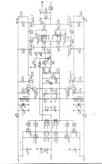
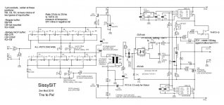
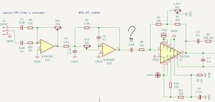
last , hopefully most clear and informative schematics are here , take care to read all notes !!!!!

Edit on 02.11.2018. :

Populating pcbs :
- as always , mount first all resistors , take care to slightly elevate R8 - to ease measurements across it while setting current through input buffer JFets
-if you're eager to try Borbely White Cathode Follower thingy (input buffer iteration) , read note on left top of schematic ; if you're lazy to do that , just ignore 1-pin sockets you got and normally solder parts , according to mentioned note
-diodes - everything pretty straightforward , except ZD1 - for Babelfish M25 orientate it as silkscreen is showing , for SissySIT orientate it contrary/opposite to silkscreen
take care that Babelfish M25 is having differently connected protection diodes than SissySIT; for B. M25 populate on pcb just those positions shown on B. M25 schematic , for SissySIT populate on pcb just those positions shown on SissySIT schematic !! ...... but you already know that , because you studied both schematics in detail :rofl:
- two tiny (isolated) wire bridges on right channel pcbs - mount it just for SissySIT , you don't need it for Babelfish M25
-solder trimpots in place , take care of notes in schematic about their initial setting value; it is absolutely essential!!!.... ignore left-right , use ohmmeter to check resistance
-solder all caps , be careful with polarity ..... I tried to ease life for all of us , putting + mark for each position , where it belongs
-solder BD transistors , take care of pinout - metal tab goes where thick stripe on silkscreen is - for both channels metal tabs are looking one at another ; slightly separate them , just to be sure that there is no possibility of contact between them
-solder 7805 regs ; again - metal tab goes where thick stripe is on silkscreen ; don't ask did I made a mistake of mounting at least one backwards :rofl:
-solder optocouplers ; it's logical looking at silkscreen where corner dot goes ; if it isn't logical to you , see post #593 Babelfish M25, SissySIT - general building tips and tricks
-solder JP pins , leave it open for now , and close it (with that red plasticky thingie) only later when you set buffer DC output offset
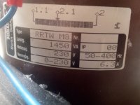
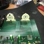
-regarding signal xformers ....... as written in previous thread(s) , pcb is made that you can use either Edcor PC600:15K (same one as in M2) , or Jensen JT-123-FLPCH (same one as in M6) , or Cinemag CMOQ-4LPC (same one as in DEFiSIT and SIT-3) .
choose which you want , according to myths and legends , and expect to follow this procedure for Cinemags - locate pin 1 per datasheet , mark it with red dot , then cut pins 1 , 6 , 7 and 12 .......... (no fuss - they're unconnected anyway) ..... that solution was absolutely essential , to be able to squeeze pads for all 3 types .... then find proper orientation on pcb and solder them on pcbs
if you are not using Edcor , and you didn't read notes on schm and you already soldered R13 , just cut it's pins :devilr:

some pics of necessary xformers trickery , post #62 , Babelfish M25, SissySIT - general building tips and tricks
More about xformer trickery - Cinemag pinout and orientation on pcb , post #652 , Babelfish M25, SissySIT - general building tips and tricks


Edit on 05.11.2018. :

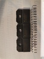
-prepare mosfet(s) , bending their pins up ; in case of Babelfish M25 - because they're practically covered with pcb so you can't see type , it's impossible to see later did you put proper one in position , so maybe is clever to use white permanent marker and write "240" and "9140" on narrow top surface of mosfet case , so later you can check are they properly mounted ; again - don't ask did I tried functionality of Babelfish M25 with two IRFP240 , instead of 240+9140 :rofl:
-it's clever to use Keratherm - bought either from Store , or from conrad.de , for Greedy Boyz being on my side of Big Splash
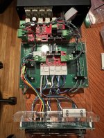
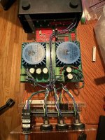
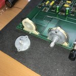
-put mosfets on/under the pcb , in exact arrangement with mounting hardware as can be seen in posts #2 and #3 , just bellow this one ; to remind you , exact arrangement is :
heatsink-Keratherm-mosfet-pcb-big washer-smaller washer if needed-springie washer as absolutely necessary part-bolt
tighten with brain , not force , but not skimp on necessary force ; my solution is to always use stainless steel washers and especially Allen bolt , because nowadays that's only way to have certainly mechanically proper part ........ usual steel bolts are more often utter drek than not

-pcbs are made for UMS , so in case of Babelfish M25 - again see pictures - you have 3 mounting points - 2 are mosfet places , third one single bolt with plastic or metal distancer between pcb and heatsink, long as mosfet thickness ; in case of SissySIT - you have one mosfet place and 2 distancers ; that way pcb is dead spot on

-speaking of SissySIT , there you need some work regarding SIT mounting , but pretty much everything you can see from pictures in SissySIT thread , post #2 especially , but there are others ; SissySIT ; if you have doubt , ask here in thread ; better to use M4 hardware than M3 , but M3 is also OK if you strictly use SS and take care about proper support of isolating bushings etc.

mount both pcbs , and when you bolted everything as needed , then solder mosfet(s) and SIT (in case of Sissy)

Edit on 11.11.2018. :

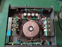
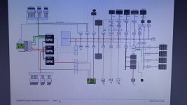
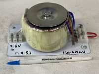
now ...... few words about PSU ...... Papa's mono PSU drawing from F6 article is handy , few more words about - read in post #113 of this thread : Babelfish M25, SissySIT - general building tips and tricks

so , say that you populated pcbs , and mounted everything in case , along with PSU ; for SissySIT - be creative with SIT mounting - take care of proper isolation of everything and proper pinout (body drain , fat pin source , thin pin gate ) and having "flying'' gate resistor as close is possible to gate itself ; heatshrink flying one together with wire , it's stronger critter that way

you didn't forget to test PSU alone ?

best to work on one channel at a time only ; if you have dual mono (which this amp more than deserves) construction , mount mains fuse in one channel only and work on it (you can work on other one , but that's hard to do anything with dead one :clown: ) ; if you have (God Forbid!) shared PSU , then wire just one channel to PSU

IMPORTANT: insert 0R1, 3W minimum , resistor in-line with negative rail ; check one more time that all trimpots are where need to be ( read notes on schmtcs) and that JP1 is open ; if you have CRC PSU filter , you can use R in CRC instead mentioned 0R1 in neg. rail ; in that case ,when you set Iq and DC offset , you're done ; don't be alarmed seeing normal surge across that resistor while caps are pulling their juice during power up

mount one DVM across outputs , 2V range ; second one across 0R1 resistor , 200mV range

input shorted , no load on output

power it up , observe output - no more than 1V or so allowed ..... if more , something is fishy - power it off and cry here ; in same time - DVM across 0R1 must stay pretty much undecided ..... few mV or so are allowed

wait few mins , calming your breathing , then turn Iq trimpot 2 or 3 turns .......... wait few mins again to see is there any positive change in readout ; any change will be slow due to enormous RC constant of biasing circuit

turn 2 more turns and observe ........ wait 2 mins and repeat - in one moment there will be change - readout increasing as 3m3 Pana cap is getting juice , which means that gates of SIT and mosfet are going one from another , thus opening both of them for current

be patient - repeat procedure of 1-2 turns more untill you get steady 100 to 120mV across 0R1 , and in same time you can play a little with DC offset trimpot , to get it closer to 0mV

let it sit for some time , to allow heat in heatsink , then fiddle with pot to get more juice in , closer to (say) prescribed 180mV , which means 1A8 flowing through OS

if you're in ballpark of - say- 150-160mV and nice offset , put lid on and wait 10min , observing readouts all the time

coffee or tea are nice to have in proximity , and use it ........

if after 10 min everything is steady , pull lid off , power off and connect other channel ... repeating entire procedure

when you have both channels at 150-160mV across 0R1 , then you can play iteratively between them , to obtain 180mV at monitoring resistor (0R1) and 0mV at output

final fiddle with lid on , of course

when everything is steady , there must be also temp equilibrium of entire case ....... power off , remove both 0R1 and solder negative rail wires in their proper places

power up , re-set output offset , let it cook , re-check offset ;

now is proper time to set input buffers - pretty straightforward procedure , read notes in schematic ; it takes just a little time

in short - put your voltmeter (DC , 200mV range ) across R8 ; fiddle with R6 trimpot to get reading of 20mV , which means buffer Iq is 20mA

connect voltmeter (DC , 200mV range ) between GND and pin1 of JP ; fiddle with R7 to get as close to 0mV you can ; pin 1 is , well - forget orientation - this is one of two pins - showing a change in readout when you fiddle with R7 🙂

when you're done with that , close JP

put lid on , put screws in place

connect cheap dumbass speakers on outputs and your Ipod/pad/phone/CD/playstation/whatever on inputs , put some musak

if cheap dumbass spks are happy , and I'm good for that - connect your precious spks and sources and enjoy

did I forgot something ?

let me know .......

aha - always test isolation between output parts and heatsink ; proper torque is your friend ; use stainless steel screw/bolts/nuts/washers ; always use springie washers , also for Graetz bridges - they are going to die if nut goes loose and they're flapping on bottom of case ; speak friendly with your neighbors .... that way you'll enjoy your music in any time of day or night ; coffee and tea are ...... good outside of an amp ;

edit on 29.11.2018.

R4 and R5 - values changed from 27R to 39R , to cover broader range of input critters Idss ; will edit schmtcs later and bug Mods to change them in this post

edit on 20.12.2018.

I decided to change value of R3 , when used as Borbely WCF - instead of 1Meg , it is now 220K - calmer transient behavior during powering ON

edit on 13.09.2019.


SIT :

body is Drain
big pin is Source
small pin is Gate

Mosfet is , name to your face , pins down - from left to right - G, D, S


SissySIT parts placement, post #1048

I'll have more if needed, but for now - 42

edit on 17.09.2019. :


P1 pre-set help post #1092 , Babelfish M25, SissySIT - general building tips and tricks

edit on 01.10.2020.

Last iteratioon of schematic , with change to 6N139 optocoupler :


schematic post #1492

pcb sshot post #1529

edit on 31.12.2020. (damned year!) :

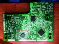
ERROR on SissySIT R2 pcb, left channel - post #1820, link : Babelfish M25, SissySIT - general building tips and tricks


ERROR No2. on SissySIT R2 pcb, both channels - post #1867, link: Babelfish M25, SissySIT - general building tips and tricks ; I'm pretty sure that's the last one 😱
Remedy shown in post #1886: Babelfish M25, SissySIT - general building tips and tricks

Attachments

  • Babelfish M25 sch with notes (1).jpg
    Babelfish M25 sch with notes (1).jpg
    110.9 KB · Views: 7,118
  • SissySIT-sch with-notes.jpg
    SissySIT-sch with-notes.jpg
    119.1 KB · Views: 7,456

too small filter resistor in CRC?

Is it possible in a CRC to have a filter resistor with such low resistance that it has a negative effect on the power supply? I've a 0.1 Ohm 3W resistor with 630 mA running through it as an external single rail 5V PSU powering a DAC. So it's only dropping 0.06V and the power is way more than required. I find that with the mids and bass lack body and weight with the resistor in place, but are normal when the resistor is replaced by a straight wire. (Vishay RS02B)

Cheap cermet trimmer pots? A nice way to trim the budget?

I normally buy Bourns but recently stumbled across Tayda Electronics and couldn't resist the $0.28 Alpha cermet 25 turn knockoffs. Did I save money or do I have a pot- load of junk on the way? I'm all for saving a little where it makes sense but my dad's voice was ringing through my head as I shopped that site... "it only cost a little more to go the cheap route".
What's your experience?

Clone SERVO CD HECD-019A for PHILIPS CDM12.1

I cloned the HECD-019A servo board for the tested and working Philips CDM12.1 mechanics.
Now I find myself with a problem.
I had to remove the P87C58 micro controller from the original board because the LQFP44 version is not for sale, I was able to find the PLCC44 version chip that I mounted on the new PCB but it does not work and therefore to make the prototype board work I had to remove it from the original board .
Now a doubt arises, does anyone know if this Philips controller, the P87C58 has a part of memory and therefore must be programmed?
Thanks for your help!

Attachments

  • IMG_3402.jpg
    IMG_3402.jpg
    475.8 KB · Views: 547
  • 1b934548-740c-4f51-8f1b-5e9f0b148f51_1.jpg
    1b934548-740c-4f51-8f1b-5e9f0b148f51_1.jpg
    508.8 KB · Views: 609
  • Senza titolo-11.jpg
    Senza titolo-11.jpg
    532.3 KB · Views: 609

Chassis Plate Mains AC Wire Protection - Mains protrusion through the perforated plate.

"This design is a grommet washer to protect wires protruding through the bottom plate, typically done with mains wiring"

This is a very simple design to provide a 3D print grommet that "snaps" into a 12mm (or 1/2 inch for Version 2) hole drilled into the bottom perforated mounting plate for Modushop (or any metal plate for that matter) chassis. Instead of using the "lip up" approach to the bottom plate, which allows for mains wiring to sneak underneath from back to front, you can use the "lip down" approach (slightly less restrictive for mounting) and instead drill two large holes at the front and back of the plate. The grommets purpose is nothign more than to protect the mains wires from abraision damage which could potentially results in a mains-to-ground short if the insulation were to become damaged. There are two versions I've created. Version 1 for a 12mm hole (I used a 15/32 drill bit) whereas version 2 is for a slightly larger 1/2 inch hole (not yet confirmed it fits, but the dimensions implies it'll work fine).

I've included a zip file for each of the two versions that includes both STL and 3MF files. Happy to tweak the design for other hole diameters via a PM request with actual measurements, and post a new version. I've also included the current Fusion 360 file so anyone can modify the part to the hole size they desire (just know it may require tweaks to the design based on fillet dimensions used). Please post modifications here so others can benefit from your design tweaks/updates/remixes.

Printing Instructions
  • No need for supports. No brim needed if you use a good "sticky approach" to bed adhesion (I use a glue stick).
  • Ensure the print is solid by increasing wall count appropriately (aka, no "fill")

Install Instructions
  • Drill the appropriate holes in your chassis where you want the mains wiring (or any wiring you want to run under the plate) to go (12mm or 1/2in based on available drill bit sizes and "version")
  • You simply "snap" the grommet washer into place from the top down using a significant amount of pressure (a hammer may be required to snap it in depending on how accurate your drilled hole is). It's a very solid "lock" into the hole (zero adhesive of any type required).
    • Note that this design is DIRECTIONAL in how it's installed, and the crescent shaped cut out is where the wire bends at and turns toward the next protrusion, so pay close attention as you snap it into place. Once it's in, it's difficult to rotate orientation (not impossible, but not easy...requires a pliers)
  • Now you can run your wires down through the perforated plate knowing they won't be damaged by the sharp metal edges on the hole.

20240317_011928.jpg


1710662484375.png

1710662863725.png


20240315_224917.jpg


20240315_230059.jpg


Finished product...
20240317_035513.jpg

Attachments

ACA toggle switch

Hi everyone, I write from Italy and I apologize if my English is not good, I am building an ACA version 1.8 and I do not find any information if the rear switch to choose the mono or stereo or xlr mode etc .... is it to be mounted in a specific direction or I can choose to do it as I want. I mean I have to respect a assembly direction with a specific pin up or down? Thank you very much.

SE to Balanced line buffer

Hi, I have a quad set from the store consisting if a pair of lsk170 and a pair of lsj74. I also have 12 extra j113s with bias resistors from the 6-24 crossover. Is there an SE to Balanced circuit that could utilize those devices that would be effective in driving a long 15-20' interconnect to a balanced pre? Or would it be more effective to use an edcor or cinemag transformer? I'm hoping to avoid having to get transformers. I have both +dc and +- dc supplies available.

Info or ID request.

I bought a set of mirrored 6550 push pull mono blocks yesterday.
The owner didn't have much info on them.
I paid a good price not knowing what the transformers are. Does anyone recognize the amplifiers or transformers?
They originally ran 4x 6550s with 5687 direct coupled cathode follower drivers, fixed bias, pentode mode, push pull parallel for something approaching 200w output power.
Any clues or info would be much appreciated.
Each amplifier weighs more than a 50 pound bag of chicken feed.
Chassis are 11" ×17" and the big caps are nearly the size of a can of beer.
What have I gotten myself into this time?
20240317_111746.jpg
20240317_080552.jpg
20240317_080542.jpg
20240317_080534.jpg
20240317_080443.jpg
20240317_080439.jpg
20240316_172634.jpg

Thank you in advance.

Fuse between SMPS & Class D amp

Hi
I could use assistance determining the value of the fuse between my 24:v/10A SMPS and 4 channel Sure Class T ("100Wx4")) amplifier.
Note I only plan to use 3 channels in a triamplified stack ( i.e. one PS & amp board per channel driving midbass, midrange and tweet from an electronic Xover.I don't play very loud.
On the 24v rail, what amperage fuse would you recommend?
Thanks in advance,
-Charles

Old 2.1 to portable

First time here sorry if something is off.
Few weeks ago I bought old Logitech x230 speaker set from flea market for 6euros. And now I got my self x530.
I'm asking if it would be good idea to make them into portable speaker(s)?
I know it's not that efficient but still it sounds like fun project and then i would have little version for bigger boombox that I've built before.
Or I could just keep it as pc speakers because my setup lacks speaker that's wired and usable at seconds notice.
My biggest problem with this is they input 230volt and I don't know if the amp accepts 12volt or something like it inside or is it purely 230volt amp

If you have experience turning old speakers into portable versions please write the experience pros and cons. Thanks

Broken Rotary switch shaft CTS 137 series

Hi all. After recapping this B & K Pro 10 Mc preamp I was aligning the knobs on the Input and Record controls when the aluminum split shaft rotary switch shaft finally gave up. B & K used dual set screws with these aluminum shafts probably knowing they would be destroyed after awhile.
It a CTS 1379038 2 pole 6 position. About as Hard to find as they come. I posted here hopefully thinking someone has been here before. I sold electronic parts over the counter for 15 years so I can normally find a part if it exists.
I have replaced controls like this doing a hardwired job, but I was hoping to avoid. Yes wishful thinking.

Attachments

  • IMG_6040.jpeg
    IMG_6040.jpeg
    802.3 KB · Views: 96
  • IMG_6038.jpeg
    IMG_6038.jpeg
    669.9 KB · Views: 101

Building a digital stethoscope

Hi,
I am trying to buildt a custom contact mic using https://www.richardmudhar.com/piezo-contact-microphone-hi-z-amplifier-low-noise-version/ (circuit picture below)
1710497909253.png


I want to record frequencies in range if 5-20 Hz. I simulated the circuit in ltspice and found better frequency response at the lower frequencies by replacing C1 by 100uF capacitor.
Frequency response:
1710498120869.png


I am looking for comments and suggestions for this change also can anyone suggest a suitable amplification circuit for amplifying mainly the lower frequencies (after the pre amplification).
My objective is to convert the microphone output into digital signal and process it further

Some filter questions

1. when designing filters, how much should I worry about phase shift, is it that important eg can a 45deg shift be heard?
and if it is important how do you correct the phase in a passive filter?
2. when would you choose to use an active filter over a passive filter?
3. how do you choose between using a 1st order or 2nd order filter
4. What is the gain (I know it’s negative), of a 1st order and 2nd order passive filter?

thanks

reducing number of decoupling capacitors

Dear friends!
I'm designing a subwoofer amplifier using TDA7294. The summing amplifier and active LP filter is based on the NJM4580.
My questions:
1) I have 3 decoupling capacitors C1, C4, C5. Are they all needed or is it possible, for example, to remove C5? Or vice versa, remove C1 and C4, leaving C5?
2) I have the opportunity to use NJM4580, LM833DT, TL072CDT and LM358DT op amps. Which one is the best?
Thank you very much!

Attachments

  • Clipboard01.jpg
    Clipboard01.jpg
    89 KB · Views: 158

Feedback on layout for point-to-point Nelson Pass Buffered Pre (and trouble shooting)

Hi! It's my first time building purely from a schematic. I put a lot of thought into the layout and have it all assembled yet it's not passing sound. Unless I crank the power amp and then there's just an almost inaudible amount present. I guess I want to get some feedback on the layout... specifically if I've read the schematic right and translated it to a physical layout accurately. Second, do you have any thoughts on why it's not passing sound? Could be the layout and honestly the transistors are a bit confusing... Below I've attached the original schematic, the PS layout, and a single channel.

I should note I'm using a 24V volt power supply as the preamp documentation says it will accommodate 18V - 24V.

Thanks!
Jonah

Screen Shot 2024-03-13 at 6.21.54 PM.png
Screen Shot 2024-03-13 at 6.31.44 PM.png
Screen Shot 2024-03-13 at 6.31.53 PM.png

Pioneer A-757 - repair or recycle?

Hey people,

someone gave me this amplifier, which has been lying around in a garden-shed for the recent 5 years. It's about 30 years old and, if one is into integrated stereo amps, it's a nice amp to keep ( look at the specs, it's massive, powerful and even stable at 2 Ohms).
First repair was an electrolytic which was responsible for the speaker-output relais, which didnt pull. That was a known issue with this amp and I had a fitting electrolytic (ELNA 3,3µF/100V instead of ELNA 3,3µF/50V) in my spare-parts box,
Now it plays music, but only in "direct"-mode. The tone controls aren't working. I think I could repair it, with some more internet-recherche and some trial & error. Cannot be so difficult.
But, what could I do with this machine? I'm into activ speakers, so I've got no use for such a dinosaur. First I thought about selling it, but this thing has 20kg. Sending it as a parcel will be difficult, not to say impossible.
Another thought is, taking it apart and using it as a subwoofer amplifier. It could run i.e. two 10", or bridged one bigger sub, as it is 2Ohm stable. But, somehow, it would be sad, to take apart such a fine old amp.
What would you do?

best regards
J.

Attachments

  • A-757 01.JPG
    A-757 01.JPG
    226.6 KB · Views: 168

Zero bias class B2 triode driver transformer

Lots of people have used AC power toroids as output transformers because real output transformers are relatively scarce and expensive nowadays. Nothing new there. I'd guess that driver transformers are even more scarce since not every amplifier had one, even back when valve amplifiers were common. The transformer in the picture is a 120+120V to 28V 7.14A 200VA. Seeing it has two primary windings that can be used in series as a single centre tapped winding to drive the grids, we have a solution! I'd love to drive the low voltage side with a LM3875 or similar and feed the high voltage side to a pair of big triodes in zero bias class B2. Or even a pair of 807s in zero bias and driving the screens and beam forming plates plates directly and the control grid via 20K resistor. No problem supplying all the grid current needed. Anyone here tried this approach?

Attachments

  • IMG_8555.JPG
    IMG_8555.JPG
    460.1 KB · Views: 106

having issues with unsoldering

I'm currently recapping my arcam delta 290p (started on 1 of 3)
i am having an issues where once the small cap is out the hole get filled with solder that i cant get out or melt
i have used a desoldering tool
it just keeps getting worse the more i try.

has anyone get any tips i have thought to get a 0.3mm drill bit but i really dont want to go down that road.


thanks for any help

Also i use the hakko FX-888D and EDSYN DS017 DESOLDER TOOL

Wavecor WF152BD07 4ohm. What would you build with this driver?

I have a pair of Wavecor WF152BD07 4ohm drivers. Really nice 5 1/2"ers with Balanced drive. Originally thinking a small bookshelf speaker for my TV room, but now I am using a sealed box with a SBAcoustics SB17CRC for that application.

So, What would you build with the Wavecor? Bookshelf? Use it as a mid in a 3way? I am open to suggestions.

All Diyaudio Threads about not available Optical Pickup's from Sony's KSS-Series

There are many threads about SONY's laser heads (optical pick up's) from the KSS-Series. I have started also some threads in this case. The reasons are clear. First the no longer availability of most of them and second the big error rate sometimes after a short time of use. In general - from all laser units that I know, Sony's laser heads above KSS-120 by far the worst of all (life time, reliability), even the models for the ESPRIT series like KSS-272A. Two main reasons are therefore responsible:
1) the suspension of the collimator lens (plastic leaf spring instead spring wire)
2) the diode itself
Obviously it can happen sometimes (fortunately not often) that other laser head manufacturers than Sony also used such worse Sony diodes. If by such older CD players the RF level very low, you can assume, that a Sony diode is inside.

By JVC-, Pioneer- and Hitachi laser heads after more than 20 years in use there are still virgin light power (after lens cleaning) and thus good level by RF signal. Also the tracking behaviour isn't impaired due collimator lens suspension without plastic.Unfortunately for most brands SONY was the main supplier of optical pick up's.

After a certain time this threads are relatively hard to find. Therefore at bottom an URL overview of all threads from diyaudio about SONY's KSS series.
If one of you discover additional threads that I have overlooked, you can add here

Basic subjects regarded KSS Series from Sony
http://www.diyaudio.com/forums/digi...ter-laser-death-great-vintage-cd-players.html
http://www.diyaudio.com/forums/digi...ser-pickups-why-not-replacing-diode-only.html
http://www.diyaudio.com/forums/digital-source/25540-sony-cd-head-repairs.html
http://www.diyaudio.com/forums/digital-source/88928-electrical-adjustment-laser-pickup.html
http://www.diyaudio.com/forums/digi...uccessor-sld-104u-sony-esprit-kss-series.html
http://www.diyaudio.com/forums/digi...ick-up-cd-player-wholesaler-manufacturer.html
http://www.diyaudio.com/forums/digi...k-about-sonys-kss-optical-pick-up-series.html
http://www.diyaudio.com/forums/digital-source/38894-full-range-sony-cd-laser-pick-ups-photos.html
http://www.diyaudio.com/forums/vendors-bazaar/108098-new-optical-pickup-spare-parts-arrive.html
http://www.diyaudio.com/forums/digital-source/133261-whining-kss210a-after-replacement.html (adjustments)

Threads about KSS120C / KSS123A / KSS-152A
http://www.diyaudio.com/forums/digital-source/158651-kss-122a-kss-123a-they-interchabgeable.html
http://www.diyaudio.com/forums/digi...ns-magnetic-linear-rails-laser-transport.html (KSS-123A)
http://www.diyaudio.com/forums/digital-source/155077-revive-heavy-weight-denon-dcd3300.html (KSS-123A)
http://www.diyaudio.com/forums/digital-source/96953-disc-table-height-kss-laser-units.html (KSS-123A)
http://www.diyaudio.com/forums/digi...ichi-oms-5eii-7eii-weak-error-correction.html (KSS-123A)
http://www.diyaudio.com/forums/digital-source/67783-test-cd-cd-player-adjustment.html (KSS-123A-151A)
http://www.diyaudio.com/forums/digital-source/109082-trying-repair-old-onkyo-dx-1500-a.html (KSS-152A)
http://www.diyaudio.com/forums/digital-source/79903-luxman-d-105u-transport-identification.html (KSS-152A)
http://www.diyaudio.com/forums/digital-source/158453-sony-kss-152-replacement.html

Threads about KSS-151A
http://www.diyaudio.com/forums/parts/153347-laser-sony-kss-151-fore-denon-cd-s1.html
http://www.diyaudio.com/forums/digital-source/157687-kss151a-kss-151a-10-x-new.html
http://www.diyaudio.com/forums/digital-source/147776-laser-replacement-teac-vrds-10-a.html (KSS-151A)
http://www.diyaudio.com/forums/digital-source/27647-kss151a-laser-replacement.html
http://www.diyaudio.com/forums/digital-source/88594-how-evaluate-laser-pick-up-remaining-life.html (KSS-151A in CDP338ESD)
http://www.diyaudio.com/forums/digital-source/89000-laser-diode-current-kss-151a.html
http://www.diyaudio.com/forums/digital-source/91184-denon-dcd-1520-not-recognise-some-disc.html (KSS-151A)
http://www.diyaudio.com/forums/swap-meet/127868-fs-kss-151a-laser-pick-up.html
http://www.diyaudio.com/forums/swap-meet/119113-fs-sony-kss-151-laser-mechanism.html
http://www.diyaudio.com/forums/digital-source/67783-test-cd-cd-player-adjustment.html (KSS-123A-151A)
http://www.diyaudio.com/forums/digital-source/27376-laser-replacement.html (KSS-151A)
http://www.diyaudio.com/forums/digital-source/53874-kss-151a-pickup-wanted.html (KSS-151A needed)
http://www.diyaudio.com/forums/swap-meet/134760-fs-sony-kss-151a-laser-head.html
http://www.diyaudio.com/forums/digital-source/75337-wadia-drive-8-laser-unit.html (KSS-151A needed)
http://www.diyaudio.com/forums/digital-source/135202-sony-cdp-950-vs-m95-vs-222esd.html (KSS-150A-151A)
http://www.diyaudio.com/forums/digital-source/100420-teac-p10-transport-what-laser.html (KSS151 or KSS213 ?)

Threads about KSS-272A
http://www.diyaudio.com/forums/swap-meet/99773-wanted-laser-pick-up-kss-272-a-3.html
http://www.diyaudio.com/forums/digital-source/132147-kss272a-working-not.html
http://www.diyaudio.com/forums/digi...er-pickup-adjustment-accuphase-cd-player.html (KSS-272A)
http://www.diyaudio.com/forums/digital-source/89220-accuphase-dp-90-laser-head.html (KSS-272A needed)
http://www.diyaudio.com/forums/digital-source/43349-sony-cdp-x779es.html (KSS-272A needed)
http://www.diyaudio.com/forums/digital-source/97681-sony-cdp-x707es-diy.html (KSS-272A needed)
http://www.diyaudio.com/forums/swap-meet/122407-wtb-new-sony-khm-230aaa-kss-272a.html
http://www.diyaudio.com/forums/swap-meet/85287-wtb-sony-kss-272a-laser.html
http://www.diyaudio.com/forums/parts/99774-hard-find-laser-pick-up-kss-272-a.html
http://www.diyaudio.com/forums/digital-source/132147-kss272a-working-not.html
http://www.diyaudio.com/forums/digital-source/39405-sony-cd-laser-replacement-availability.html (KSS270A-KSS272A)

Threads about KSS-270A / KSS-271A / KSS-273A-B / KSS-281A
http://www.diyaudio.com/forums/digi...ble-use-kss240a-cdpx55es-instead-kss270a.html
http://www.diyaudio.com/forums/digital-source/154699-cdp-x333es-kss-271a-tracking-offset-probs.html
http://www.diyaudio.com/forums/digital-source/154669-cdp333es-skips.html (KSS-271A)
http://www.diyaudio.com/forums/digi...ter-laser-death-great-vintage-cd-players.html (KSS-273A)
http://www.diyaudio.com/forums/digital-source/82754-sony-optical-pick-up-kss-273-a.html
http://www.diyaudio.com/forums/digital-source/105295-laser-kss-273-b-hard-find.html
http://www.diyaudio.com/forums/parts/100577-need-help.html (KSS-273B)
http://www.diyaudio.com/forums/digital-source/30585-sony-cdp-x777es.html (KSS-281A needed)

Threads about KSS-240A / KSS-213A-V / KSS-210A / KSS-150A
http://www.diyaudio.com/forums/digital-source/81103-broken-arcam-alpha-8-trichord.html (Sony CDM-14/KSS-240A)
http://www.diyaudio.com/forums/digital-source/82612-troubleshooting-pick-up.html (KSS-240A)
http://www.diyaudio.com/forums/digital-source/101935-denon-dcds10-cd-player.html (KSS-240A)
http://www.diyaudio.com/forums/digital-source/32730-teac-vrds-t1-cd-transport.html (KSS-240A)
http://www.diyaudio.com/forums/parts/39473-sony-mhc1600-hcd-h1600.html (KSS-240A)
http://www.diyaudio.com/forums/digital-source/139605-kss-240a-based-transport-diy-player.html
http://www.diyaudio.com/forums/digital-source/100978-cdp-591-a.html (Solder bridge KSS-240)
http://www.diyaudio.com/forums/digital-source/108381-sony-laser-arcam-mcd.html (KSS-213-240)
http://www.diyaudio.com/forums/digital-source/26399-kss-213-laser-family.html
http://www.diyaudio.com/forums/digital-source/85363-taking-apart-rega-planet.html (Rega Planet 2000-KSS213B)
http://www.diyaudio.com/forums/digital-source/126608-sony-mhc-rv22-cd-section-problem.html (KSS-213B)
http://www.diyaudio.com/forums/digital-source/59654-tascam-cd-302-modifications.html (KSS-213B to C)
http://www.diyaudio.com/forums/digital-source/107257-cd-player.html (MHZS33-KSS213Q)
http://www.diyaudio.com/forums/digital-source/95276-sony-cd-player-optical-pickups.html (KSS-213A-V/KSS-210A-C)
http://www.diyaudio.com/forums/digital-source/96961-rotel-rcd930ax-help.html (KSS-210A-D)
http://www.diyaudio.com/forums/digital-source/94694-naming-conventions-sony-drives.html (KSS-210-KSM2101)
http://www.diyaudio.com/forums/digital-source/77734-sony-laser-alignment-kss-nad-cd.html (NAD502/512-KSS-210A)
http://www.diyaudio.com/forums/digi...8-based-sony-philips-need-service-manual.html (KSS-150A)
http://www.diyaudio.com/forums/digital-source/107757-comments-onkyo-dx-703-a-2.html (KSS-150A)

Threads about other KSS models
http://www.diyaudio.com/forums/digital-source/74910-sony-bu-1e-laser.html (Laser head without type No - BU = Base Unit = transport mechanism)
http://www.diyaudio.com/forums/digital-source/140856-heavyweight-sony-laser-loader.html (KSS-100A)
http://www.diyaudio.com/forums/digital-source/46796-laser-mechanism-sony-ex7esd.html (KSS-190A needed)
http://www.diyaudio.com/forums/car-audio/141649-kenwood-kdc-m9021se-laser-unit-problem.html (KSS 24430 Car Hifi)
http://www.diyaudio.com/forums/parts/21016-anyone-knows-where-can-i-buy-sony-cd-pick-up.html (KSS-331C needed)
  • Like
Reactions: nanocamp

Help with a Sansui G-5500, tripping relay after restoration

Looking to see if anyone can help steer me in a different direction than I’ve been going with a Sansui G-5500. It belongs to a friend of mine who asked me to diagnose a problem that I could not duplicate, and once we knew it was pretty solid we decided to do a restoration on it; change out the caps, trim pots, full cleaning etc.

So this worked out originally, and the unit was perfectly fine after the work. A month or so later he told me it was popping through the speakers even at low volume, so I have it back here again.

I have not been able to duplicate the issue he was having, but instead somehow introduced a new one which was that the unit was now going into protection when I was about halfway up on the volume level (sinewave test). In playing around with stuff I’m not sure how I did it but I managed to blow the outputs on the right channel. So I replaced them with the NJW equivalent subs and once I knew those were ok I also replaced all the sketchy driver transistors that I didn’t feel needed to be done the first time around. Now I am getting the relay to click into protection at about a quarter of the volume. Same input level, and also still no right channel.

I’m not sure if I’m concentrating in the right area right now because I’m getting flustered on this one. Anyone here familiar with the G-5500 by chance? I did check the stupid stuff like open emitter resistors, and I have pulled all my replacement parts and double checked. I’ve also replaced the HA12002 protection IC because I thought maybe I had damaged it when I was cleaning the corrosive glue away on the board. All the voltages look fine there, as well as on both channel outputs I’m getting my +/- 43v. I’m just a bit stumped at the moment…

Recommend me the woofer for my big Heresy

Hi everyone, I'm starting a new project for the heresy big version (Klipsch Forte style), the components will be:
-B&C DE10 tweeter
-K53k medium with 15" horn.
As for the woofer, I don't know, I have selected some models that I can easily find, with a price around €150 and they are:
Eminence beta 12A (I already have this one)
B&C 12NDL76
RCF LF12X401
Dayton pa 310-8
LaVoce waf122.50
For each I attach the technical data sheets.
The dimensions will be approximately 100l like the FASTLANE AUDIO version with 4" port.
Which of these woofers might be best for you? I chose these because they are easy to find and affordable, but I could use others in that price range.

Thanks
1000054165.png
1000054166.png
1000054167.png
1000054168.png
1000054169.png

Grado Labs Prestige Series SR80 Headphone repair Help

Good afternoon. So I have had my Grado Labs Prestige’s Series SR-80 headphones for 28 years now. They have been sent back 1 time for the plastic part that holds the head band on and a wire finally broken in the middle. Well after sending them in to get repaired from 5 years ago it has happened again. I don’t want to send in my headphones for repairs I would like to fix it my self (if I can?). So where I began this repair is asking all of you what wire can I buy in bulk to repair the wire? I can buy, a wire pants boot Y splitter and the 3.5mm connector end. I can solder and I have a soldering station for that. So with all this out of the way now here’s a few final questions?
1. What kind of wire can I use? Balance or unbalanceed wire? Does it make a difference’s in the overall sound?
2.How does the plastic piece covering the driver come off to expose the wire so I can replace it?
3. Will the ohms change if I switch the wire and will it Be close to the ohms the head phones are now? I hope am not being too critical or going overboard?

Here are the wire Companies I am familiar with over the years that I have used in 1 way or another.

1. Gotham Audio.
2. Mogami Wire.
3. Canare Wire.
4. Supra Cables
5. Parts Express’s house brand now (Audtek).
6.Kimber Cable. (Diy stuff only).
7. Duelund Cables. (Given to me only 4 feet).
8. Wire World Cables.
9. Linn Speaker Cables.
10.Audio quest (years ago $5.00 bulk speaker cables).
11. Mono Prices 12 gauge wire (40 feet of it years ago).
12. I hate to say it last but, not least Monster cable ugh I said it. 🫢.

A lot of cables and info. I now it was a long post but, I wanted to put everything out on the table to see where I can go from here? Thanks for reading my post. Here are 2 pictures of the head phones with the wire showing and just my headphones model and series. Thanks Jeff

Attachments

  • IMG_3392.jpeg
    IMG_3392.jpeg
    804.3 KB · Views: 123
  • IMG_3394.jpeg
    IMG_3394.jpeg
    403.6 KB · Views: 94

Altec 515B: speaker enclosure

Hi,

I have one Altec 515B that needs a speaker cabinet, the woofer will be matched with a 288 driver and a 1005 multicell:

I am very eager about this project, but a DIY project that incorporates the original A5 cabinet is not the way I want to go..

I was wondering if anyone had inputs on which way to go: traditional bassreflex, do fancy the Altec 612 cabinet proportions, but is an Onken design also a way to consider with the 515B?, how big volumes are we talking about : question concerns both the traditional bassreflex ( Altec 612 ), but will a Onken design for a 515 be bigger the 360L Onken?

The whole system is rated 20 ohms... the 515 first needs a recone, guessing there is no point in measuring ( Dayton DATS ) the woofer before that time...

Unknown diode

Can anyone help me identify this diode? They come from an Audiosonic ST-8000, about which no information can be found. It appears that the diode with 689mv is defective.
I want to replace them both and thought about 3x or 4x 1N4148, but when measuring I can't get an exact result/match. (By the way: Uf 2.59v on the tester gives Uf 2.21v on my multimeter with leads)
Does anyone have any good advice? Thank you!

Attachments

  • 20240313_194940.jpg
    20240313_194940.jpg
    231.9 KB · Views: 232
  • 20240313_195001.jpg
    20240313_195001.jpg
    244.9 KB · Views: 217
  • 20240313_181400.jpg
    20240313_181400.jpg
    332.6 KB · Views: 219

Stovey

'Lil Stovey'

IMG_20240307_150218.jpg

It's kind of an art project, but also a fully functional 5 gallon bucket shop sub with a chimney port.


8" driver from a Sony bookshelf system

Metal, wood, plastic, bedliner, acrylics

IMG_20240307_140436.jpg

IMG_20240307_140442.jpg

I have a few build photos but it seems pretty self-explanatory? 🙂

It was fun having an excuse to use an external port.

The holes in the chimney are so the port length is at the holes, but the chimney is visually as tall as it is. I think they might whistle a little at the very highest volume due to the relatively sharp edges, so I probably won't do that again. The straight part of the chimney is removable and usable at a higher tuning without it (the elbow alone is around 8 inches of port length, best as I could tell).

I learned that common buckets are HDPE, so nothing really sticks to them... I used PL 3x as a sealant but the end caps are mechanically fastened with (many) screws.

It's running full range in the video but will be crossed over to a matco 'bumpboxx' (which seems to have a nice volume-controlled line-out). And the video is just to show off the looks, not for the sound, fwiw 🙂

B&W Matrix 805 problem

I have recently purchased a Matrix 805 from a friend. Have been using it since the past 3 months and it performed very well. Since last morning, I am only getting the tweeter to work on one speaker. The mid-woofer is not working. Tried swapping to the other amp and problem is definitely with the speaker. The tweeter is working well. Opened the back panel and everything seems connected perfectly well at the binding posts as well as the driver side in the front. Please guide me if this is a Crossover problem and how I can diagnose it. Thank you

For Sale miniDSP nanoDIGI 2x8 audio processor and active crossover

Discontinued by miniDSP, but this processor still delivers the goods, especially on a channel-per-dollar basis.

In short:
  • 2 channel input (1 stereo SPDIF coaxial in or 1 Toslink optical in, both stereo)
  • 8 channel output (4 stereo SPDIF coaxial outputs)
Read the plugin spec here.

Works perfectly and will include the plugin software for both Mac and Windows for free.

Available for local pickup in the SF Bay Area

Asking $140 shipped in the US but open to reasonable offers. Global shipping available, message me.
Thanks!

Also selling 2 Soncoz DACs that I used with this miniDSP to create a killer budget active signal path.

Attachments

  • _VCL8465.JPG
    _VCL8465.JPG
    155.3 KB · Views: 161
  • _VCL8464.JPG
    _VCL8464.JPG
    158.7 KB · Views: 174

Hello everyone My New Head Phone Amp

Hello everyone

I’m thrilled to join the DIY Audio community. As an avid enthusiast of audio engineering and a DIYer at heart, I’ve been passionately involved in creating and tweaking my own audio equipment.

My latest project, a headphone amplifier that has CR-type phono equalizer and I have employed a circuit that applies the same amount of feedback to both the inverted and non-inverted outputs of the balanced output.

I look forward to exchanging ideas, learning from the community, and contributing to our shared passion for high-fidelity sound.😊

Best regards, Eri Hiromu

Attachments

  • Image_HD_PHONE.JPG
    Image_HD_PHONE.JPG
    93.9 KB · Views: 109

Focal Kevlar Speaker Chassis 5K013L vs. 5K4211

For repair of an old Focal Point Source Aria Five (from 1993, Manfred Zoller HiFi Design)
I want to know the difference between this two chassis models.
5K013L is to find here:
http://nedlab.com/wp/wp-content/uploads/2014/06/5k013l.pdf
http://www.diyaudio.com/forums/swap-meet/182448-4-focal-kevlar-5k013l-midbass.html
5K4211 is to find here:
http://www.diyparadiso.com/datasheets/speaker/focal/5K4211.jpg
Which of this both is the best choice?
Thanks for advices.

Attachments

  • Focal Point Source diy.jpg
    Focal Point Source diy.jpg
    863.1 KB · Views: 894

GB For Salas I-Select Mesmerize Type input selector and volume control

The I-Select board takes the selector functionality and volume control from the old mesmerize boards and implements in a standalone fashion.


This gives one a relay based selector control, relays perform reliably with great longevity and have superior electrical isolation characteristics.

This can also act as a standalone passive preamplifier, or be tied to the input of the DCB1, DCG3 or any other type of input for that matter.

The boards are $16.00


I am making a minikit available for this. It will come with no volume control, 4 inputs and a selector switch. However, read the guide, there are other ways to set this up to gather off a previous DC output voltage, and to power another unit if need be. So this is just a 'basic' type kit. More relays available on request.

4-EA2-12NJ-12V relays
8-1N4003G
1-EEU-FC1V222-Panasonic FC 35v 2200uf
1-Molex 2P Terminal Block Black
1-Headers & Wire Housings HSG 7P SINGLE ROW
1-Headers & Wire Housings 7P STRT 1 ROW GOLD 5.5MM MATING PIN
4-Headers & Wire Housings 3P STRT 1 ROW GOLD 6.8MM MATING PIN
4-Headers & Wire Housings HSG 3P SINGLE ROW NON-POLARIZED
25-Headers & Wire Housings 22-24 TERMINAL BULK
1-Wakefield 637-10ABPE heatsink
1-7812 voltage regulator
1-Rotary Switches ROTARY 2POL 6POS NS Alpha
1-Vishay MBB Through Hole .6w 10k 1% 50ppm
1-Kemet Film Capacitors .1uF 100volts 5%
1-20ma LED
$36.00

Attachments

Possible Mark Levinson 431 Problem

Hello All,
I have a 19-year-old Mark Levinson model 431 power amplifier. After sitting unused for about 2-years, I wanted to compare it to my current amplifier. I powered it up for a few days to let it warm up. While checking the input and output to adjust gains for the two amplifiers, I noted a -140mV DC at the input, the output was 0VDC. Both channels measured the same.

My question is, can that be considered normal? The manual says the input is a balanced topology, but I use it in single-ended mode. I noted that if I add a load (if that is the proper term here) of about 1K, the DC goes to zero.

Thanks for any help
Cheers,
ceulrich
Projects by fanatics, for fanatics
Get answers and advice for everyone wanting to learn the art of audio.
Join the Community
507,650
Members
7,882,730
Messages

Filter

Forum Statistics

Threads
405,964
Messages
7,882,730
Members
507,650
Latest member
Sanjiev