Hi! It's my first time building purely from a schematic. I put a lot of thought into the layout and have it all assembled yet it's not passing sound. Unless I crank the power amp and then there's just an almost inaudible amount present. I guess I want to get some feedback on the layout... specifically if I've read the schematic right and translated it to a physical layout accurately. Second, do you have any thoughts on why it's not passing sound? Could be the layout and honestly the transistors are a bit confusing... Below I've attached the original schematic, the PS layout, and a single channel.
I should note I'm using a 24V volt power supply as the preamp documentation says it will accommodate 18V - 24V.
Thanks!
Jonah


I should note I'm using a 24V volt power supply as the preamp documentation says it will accommodate 18V - 24V.
Thanks!
Jonah
It looks like Q201 is wired incorrectly. Rotate it 180 degrees. Looking at the flat side of the JFET, the pins are D G S left to right.
i realize now that i made an error when i created the graphic and the shape (the flat side) doesn’t agree with the pin out. while the shape is in the wrong orientation the pin out as it relates to the schematic should be right (the drain of q201 tied to the source of q200). i think…It looks like Q201 is wired incorrectly. Rotate it 180 degrees. Looking at the flat side of the JFET, the pins are D G S left to right.
Post pictures of the top and bottom sides of your build then.
And be sure, not just think. Double check the build.
And be sure, not just think. Double check the build.
Thanks for the reply! Here are a few pics. With it being my first build directly from a schematic comes the "I think" part... I can't discern what could be out of sorts unless a part is faulty or I'm missing something glaringly obvious. Went back through it last night bypassing the power switch, LED, input selector, and volume control, and still nothing. It would be great if I had some voltages on the schematic to help with the troubleshooting. Again, new stuff for me.
The '-' of the 24V DC input is grounded (please ignore the long green wire).
The 1M input resistor goes from the pin to the ground on the input RCA
The 221K output resistor goes from the pin to the ground on the output RCA
I have some temporary jumpers to connect the grounds (not pictured). From the RCA grounds to the PS, the input 'boards' to the PS, etc.
Thanks!
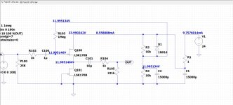
I have one channel wired, so at Q100 - when measuring from each leg to ground with nothing plugged into the inputs and outputs - I get the following.Measure the voltages at Q100/Q200 drain, gate, source.
Drain - 23.94 VDC
Gate - 10.88 VDC
Source - 11.88 VDC
Not sure what I'm looking for...
It is strange that the voltage at the gate is lower than the voltage at the source.
What is the voltage drop across R1 (1 Ohm)?
Overall picture showing everything, including volume pot?
What is the voltage drop across R1 (1 Ohm)?
Overall picture showing everything, including volume pot?
I just saw this after measuring the PS. Thanks for sending along the voltages. As far as I can tell everything checks out.There are two voltages, 12V and 24V.
First test the power supply portion for 12V and 24V. If that is correct, then connect the signal part of the circuit to the power supply and check voltages.
I did notice that C3 is missing from your model, but that shouldn't throw things off too much.
Hmmm... With one lead connected to both sides of R1, I get .008 VDC.What is the voltage drop across R1 (1 Ohm)?
I currently have everything bypassed in the circuit including the volume pot, input selector, power switch, and power LED. It's a mess of jumpers, see attached. I can send more images if you would like.Overall picture showing everything, including volume pot?
0.008V across 1 Ohm translates to 8mA, which is good, assuming that is with one channel connected. That is the current expected through the JFETs.
So for now if we assume the basic circuit is working properly, the next thing to check is the input signal. You can do that by inputting some music or better still, download a file of a 100Hz sine wave and play that and input it to the B1. With your multimeter set to VAC, black probe to ground, use the red probe and start at the circuit input and check for the signal and continue onward through the signal path.
So for now if we assume the basic circuit is working properly, the next thing to check is the input signal. You can do that by inputting some music or better still, download a file of a 100Hz sine wave and play that and input it to the B1. With your multimeter set to VAC, black probe to ground, use the red probe and start at the circuit input and check for the signal and continue onward through the signal path.

So measuring throughout the signal path - starting at the input RCA - I get 1.9 mV AC throughout with a 100Hz sine wave. Does that sound right?So for now if we assume the basic circuit is working properly, the next thing to check is the input signal. You can do that by inputting some music or better still, download a file of a 100Hz sine wave and play that and input it to the B1. With your multimeter set to VAC, black probe to ground, use the red probe and start at the circuit input and check for the signal and continue onward through the signal path.
You need to know the voltage of the signal first. What is the voltage at the output of your source? Is it a dac? I would guess it would be around 1V or so.
I’m getting about .66V from my DAC but it drops to 1.9 mV when I measure after the RCA input. If I bypass the RCA and the associated 1M resistor I get .66V all the way through the channel. Did I read the schematic wrong and place the 1M resistor in the wrong position etc? Right now it goes from the center pin of the RCA to the ground of the RCA. The signal wire also continues from the center pin of the RCA along to the channel circuitry.

Did you have the red jumper in place when you measured the low input signal after the RCA jack? If so, check the jumper.
Hmmm. It’s definitely 1M.99/Measure the resistance of the 1M resistor. Perhaps it is not 1M.
The red jumper from the earlier photo was in place. I just tried a different jumper and they’re both fine.Did you have the red jumper in place when you measured the low input signal after the RCA jack? If so, check the jumper.
- Home
- Amplifiers
- Pass Labs
- Feedback on layout for point-to-point Nelson Pass Buffered Pre (and trouble shooting)