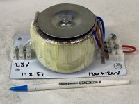
Lots of people have used AC power toroids as output transformers because real output transformers are relatively scarce and expensive nowadays. Nothing new there. I'd guess that driver transformers are even more scarce since not every amplifier had one, even back when valve amplifiers were common. The transformer in the picture is a 120+120V to 28V 7.14A 200VA. Seeing it has two primary windings that can be used in series as a single centre tapped winding to drive the grids, we have a solution! I'd love to drive the low voltage side with a LM3875 or similar and feed the high voltage side to a pair of big triodes in zero bias class B2. Or even a pair of 807s in zero bias and driving the screens and beam forming plates plates directly and the control grid via 20K resistor. No problem supplying all the grid current needed. Anyone here tried this approach?
Attachments
I've have some experience of both using mains toroids as signal transformers (only as OPTs though) and of using transformers to drive tube into class A2.
I think this would be quite a challenge, the toroid will probably not be excellent as a stepup transformer (but please try and let us know, I'm just guessing here) and then there will probably be problems with ringings when the grid voltage crosses the zero volt line from positive to negative and the windings suddenly become unloaded.
Earlier this year I ran some tests with various low Z tubes and Lundhal interstage transformers to drive a PP pair of 6B4G into class A2. Some versions where perfectly able to push the grids to +15V and above, but no amount of damping could cure the ringing.
The idea to use power opamps is interesting, I've been looking for opamps that can swing +-50V or more and 100mA to use as input/driver stages in a class A2 SET.
A torroid has no air gap and cannot store magnetism like a standard E I plate transformer with an air gap. Useless as an output transformer but OK as a matching transformer with no DC current flowing.
Surely Class B2 is non existent and should be classed as Class C, if it has no bias current flowing. Very common in poor quality amplifiers for RF transmitters, back in the old days.
B2 is a trade name owned by B2Audio.com
Surely Class B2 is non existent and should be classed as Class C, if it has no bias current flowing. Very common in poor quality amplifiers for RF transmitters, back in the old days.
B2 is a trade name owned by B2Audio.com
Oh I see - SCREEN drive. First post said big triodes, which kind of threw me for a loop when zero g1 bias was also mentioned (Wide open throttle for a triode, and proper B2 bias would be horribly nonlinear). G2 drive makes more sense as it’s transconductance at least approaches linear from low to high Ip. G2 current will still go positive and be highly nonlinear. Keeping the two screen currents BALANCED so as not to saturate the driver trafo will be the biggest challenge I think. The nonlinearities will have to be equal in order for the DC to cancel. I don’t know how well controlled those g2 currents are sample to sample. Any feedback used overall wont be correcting this either (since it’s not sampled in the output) so it is what it is and your transformer has to live with it. It would be an interesting data point to know how well this works out. How MUCH imbalance these toroids can live with is still somewhat a mystery - whether it’s 5, 10, or 15 mA for instance. All we usually do is go out of our way to keep it “low” without establishing a real threshold - knowing that if it goes too hgh you’re sunk.
I assume Circlotron is talking about 811A or similar high mu, zero bias triodes? They are sometimes used with positive grid bias in SE amps but when used in PP with high plate voltages they can actually operate with both the grids and the cathodes at ground potential at idle. Not too different from G2 drive
Fuling, was thinking the same thing with the 811A. Altec essentially did this with their 1570 amp using a pair of 811A to get 170W Class B output. Difference is they used a cathode follower/choke combination instead of a transformer. By many accounts this amp delivered the sonic goods without the usual multiple pairs of output tubes.
Yes, the 1570 uses two cathode follower and a center tapped choke, I do the same in my class A2 807 mono blocks and it works like a charm.
Mosfets would probably be better though. I'm currently working on an 808 SE prototype and I intend to try cathode follower, fet follower and inverting interstage transformer to see which one that sounds best. My guess is the mosfet.
Mosfets would probably be better though. I'm currently working on an 808 SE prototype and I intend to try cathode follower, fet follower and inverting interstage transformer to see which one that sounds best. My guess is the mosfet.
A push pull 807 with Zero volts on the screen, on a real good day or on a full moon night, might have as much as 10uA of quiescent plate current.
(Post # 7, schematic; I hope crazy drive circuit is better than that).
Old RCA AM radio transmitters for military service is not exactly Hi Fi.
Talk about crossover distortion!
Talk about damping:
Given a large voltage from a bass drum hit that quickly collapses to zero volts, there is No amplifier control of the woofer cone which is trying real hard to return to center!
To each his own.
Last edited:
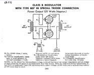
Real “crazy drive” would crack them open a wee bit more than that (some non zero bias). Still more crossover distortion than typical, though. Post 7 is for an RF modulator. Ham radio operators don’t care about crossover distortion - just how much out of band emission at (around) the carrier frequency. Filters and antenna tuners can take care of that to some extent.
Notice that RCA mentioned a push pull driver for the interstage transformer,
but that they did not dare to talk about the idea of global negative feedback that would include the interstage and output transformer.
Global negative feedback:
Not needed? Not for Hams and Military.
Not possible, right not possible. Exercise in futility anyone?
Just my opinions
but that they did not dare to talk about the idea of global negative feedback that would include the interstage and output transformer.
Global negative feedback:
Not needed? Not for Hams and Military.
Not possible, right not possible. Exercise in futility anyone?
Just my opinions
https://people.ohio.edu/postr/bapix/Eico730.htm
I have one of these in pristine condition. Still has the Eico branded Mullard tubes in it with the optional cover. People “hotrod” these to clean up the distortion. Hifi it’s not. Didn’t intend to derail the discussion. Carry on👍
I have one of these in pristine condition. Still has the Eico branded Mullard tubes in it with the optional cover. People “hotrod” these to clean up the distortion. Hifi it’s not. Didn’t intend to derail the discussion. Carry on👍
Usually people who play with driver transformers (for actual audio use, not RF modulators) do so because they have an irrational fear of capacitors. Which usually stems from hi-fi perfectionism.If this were diyhifi then yes, an exercise in futility. But it is diyaudio, so the circuit is valid for discussion regardless of how poor the results.
My bad for jumping to the assumption that one wanted “best of the best hi-fi performance” when that might not have actually been the case.
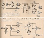
The easy way out so that your sanity is still intact is to drive the grids with a PP CF.
Adjust the bias on the CF grids so that the output tubes run a little +ve, That way cross-over distortion is reduced.
PP 807s are driven here by a single 12AU7. No need for an expensive IT.")
Adjust the bias on the CF grids so that the output tubes run a little +ve, That way cross-over distortion is reduced.
PP 807s are driven here by a single 12AU7. No need for an expensive IT.
Attachments
For the CF driving the load Gm is most important.12AU7 probably works but a high gm tube would be better, and fets even better still.
To high +ve bias on the grids of the power toobz could cause excessive plate dissipation.
As always, tradeoffs need to be considered.
- Home
- Amplifiers
- Tubes / Valves
- Zero bias class B2 triode driver transformer