Of course followers do a better job - because the load impedance abruptly decreases when the grids go positive. The follower’s output z (1/gm) tends to be a lot lower than the reflected plate impedance of the previous stage. It can absorb that change in impedance (during the cycle) without adding too much distortion.
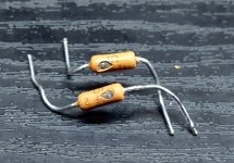
A transformer is just the world’s^H^H^H^H^H universe’s easiest way to generate two opposite phase signals. There was a time when transformers were cheaper than a tube and two capacitors. Those days long gone.
A transformer is just the world’s^H^H^H^H^H universe’s easiest way to generate two opposite phase signals. There was a time when transformers were cheaper than a tube and two capacitors. Those days long gone.
If driving them is not an issue then maybe BJT emitter followers are even better again.In my limited experience followers do a better job than transformers at pushing grids into the positive region. 12AU7 probably works but a high gm tube would be better, and fets even better still.
In my latest project I'm trying to combine the best of the two technologies: single triode input stage - transformer phase splitter - FET followers - output tubes.
The amp is currently operating without the followers and I don't expect them to leave much of a sonic signature once they're in place.
The amp is currently operating without the followers and I don't expect them to leave much of a sonic signature once they're in place.
If driving them is not an issue then maybe BJT emitter followers are even better again.
Perhaps. I don't know how the base current will affect the previous stage? Mosfets are commonly used in this position, they definitely have enough gm to make superb followers and the input capacitance is not much of a problem with modern fets and as long as the gain stage upfront doesn't have an unreasonably high output impedance.
Edit: It's a bit sad that the replies in this thread discourages the idea of using a transformer coupled driver, but I think there's a reason behind it. As mentioned, transformers don't like abrupt changes of the loading and circuits like this would probably need an healthy amount of negative feedback to fight distortion and output impedance, not an easy thing to do across one output and one interstage transformer.
Last edited:
And has wg_ski has already mentioned, if both output valves don’t draw equal grid current there will be a dc imbalance in the driver transformer, something I never thought of. 🫣
Indeed. An EI transformer could probably handle that but toroids are notoriously bad in handling DC imbalance.
Grid current is fun stuff though, I'm currently waiting for parts to finish the PP project mentioned above so right now I'm working on a pair of small SE monos with 807s driven by 6E5P cathode followers. 807/6L6 are not exactly known for producing a lot of power as triodes in SE, but a bit of grid flogging almost doubles the number from a pathetic 1,7W in class A1 to 3,3W in A2, measured on the prototype.
Grid current is fun stuff though, I'm currently waiting for parts to finish the PP project mentioned above so right now I'm working on a pair of small SE monos with 807s driven by 6E5P cathode followers. 807/6L6 are not exactly known for producing a lot of power as triodes in SE, but a bit of grid flogging almost doubles the number from a pathetic 1,7W in class A1 to 3,3W in A2, measured on the prototype.

Grid flogging - LMAO.
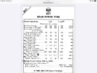
That 807 can actually take it though - it’s a 6L6-oid fully characterized for operation to vg1=+30. It can do this because of the large g2 spacing and relatively cool cathode (0.9 A). Don’t try it with an EL34.
I’ve been tempted to try it with 6W6’s to get more than it’s weight class off 170 volt plates. You should be able to guess where that comes from. Might end up in flames but they are only three bucks.
You should be able to guess where that comes from
My guess is Anderson, first name George?
That 807 can actually take it though - it’s a 6L6-oid fully characterized for operation to vg1=+30.
Yes, AB2 operation is well documented in the STC 807 application report, and in other datasheets. I have another pair of mono blocks with 807s in triode PP class A2, almost 13W from only 290V B+. The same OP would probably only produce 3-4W in class A1.
My theory is that most tubes can handle a bit of A(B)2 operation, as long as it is momentaneous. There's not much output power to be gained from pushing low mu triodes into grid current but having an A2 capable driver stage prevents blocking distortion, something that apparently can be a very real problem when small tube amps are being asked to play anything more demanding than soft background music.
The person maybe (he would do this), but I was referring specifically to the voltage. Hint: the square root of two, nothing more can be said.
Not all tubes are tolerant of much A(B)2. EL34’s will melt. But my direct drive 6550’s take a little bit of it (limited by the g1 stoppers, but the drivers themselves can give me plenty of positive drive). NO blocking distortion at all. Drive 6 dB into clip with BASS and it still sounds clean. Like a Crown Macrotech or old 1974 PV CS800 (with new capacitors of course). Surprised the hell out of me the first time I heard it. But the scope don’t lie - that son of a gun was flat-topping. Crazy loud too - I was listening 50 feet out during the first full power test that wasn’t just with a dummy load. I was used to solid state amps that could do that - I built pair of 1200 watters that could so I know what it sounds like. I ran a pair of those with 4 lab horns and nearly melted the plugs off the extension cords once. Modern cheap-o PA amps don't even come close anymore. See the first clip light come on and it’s already sounding scratchy. I like amps you can run a bit into the red and still sound clean.
Not all tubes are tolerant of much A(B)2. EL34’s will melt. But my direct drive 6550’s take a little bit of it (limited by the g1 stoppers, but the drivers themselves can give me plenty of positive drive). NO blocking distortion at all. Drive 6 dB into clip with BASS and it still sounds clean. Like a Crown Macrotech or old 1974 PV CS800 (with new capacitors of course). Surprised the hell out of me the first time I heard it. But the scope don’t lie - that son of a gun was flat-topping. Crazy loud too - I was listening 50 feet out during the first full power test that wasn’t just with a dummy load. I was used to solid state amps that could do that - I built pair of 1200 watters that could so I know what it sounds like. I ran a pair of those with 4 lab horns and nearly melted the plugs off the extension cords once. Modern cheap-o PA amps don't even come close anymore. See the first clip light come on and it’s already sounding scratchy. I like amps you can run a bit into the red and still sound clean.
"My guess is Anderson, first name George?"
I don't know anybody with that name......
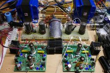
I have a box full of crusty old 6L6-oids including some 70+ year old 6L6G's and 6L6GA's. Will they eat +30 volts on their control grids? And will they do that with 500 volts in the plates? If they survive that how about dropping the load to an absurd 3300 ohms. What will happen?
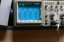
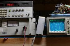
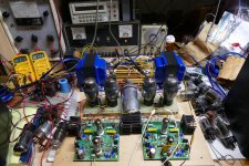
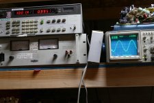
The picture shows the control grids of a pair of 6L6GA's being driven into AB2 by a Tubelab Universal Driver board which uses a mosfet for each grid. I cranked the drive up to touch +30 volts on one grid while the other saw about +27 volts. Nothing spectacular was happening. Power output was 73 watts. So, whats next? You know what's next. +50 volts on one grid and +40 on the other. Power output is 90.65 watts at 8.22% THD. It sat at this level for a couple of minutes before a pale glow was seen on one tube.
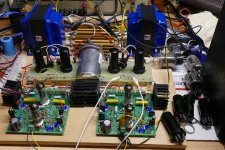
I decided to connect up the second channel and play musical tubes to find some that were better matched. I had both channels running for a while running 6L6GA's or 6L6GAY's. During this time I passed the 110 watts per channel a few times. Attempts to go beyond 110 watts ended with the same result twice. A tube arc occurred twice in two different tubes as I passed the 113 watt mark. Both times the 1 ohm 2 watt cathode resistor popped like a bad firecracker. Both times the tubes continued to work at the same performance level even after the arc.
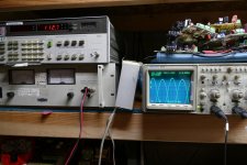
Here one grid sees about +42 volts while the other is getting about +45 volts. Power output is 112.7 watts at about 7% THD. I moved the 8 ohm load to the 16 ohm tap to reflect a 3300 ohm load on the tubes. Maximum power went down to 95.7 watts limited by red glow on the plates and grids. One look at the control grids reveals the real issue. +60 volts on one tube, and a clipped 58 volts on the other. I killed the power before killing the tubes.
I don't know anybody with that name......
Grid flogging - LMAO.
That 807 can actually take it though - it’s a 6L6-oid fully characterized for operation to vg1=+30. It can do this because of the large g2 spacing and relatively cool cathode (0.9 A). Don’t try it with an EL34.
I have a box full of crusty old 6L6-oids including some 70+ year old 6L6G's and 6L6GA's. Will they eat +30 volts on their control grids? And will they do that with 500 volts in the plates? If they survive that how about dropping the load to an absurd 3300 ohms. What will happen?
The picture shows the control grids of a pair of 6L6GA's being driven into AB2 by a Tubelab Universal Driver board which uses a mosfet for each grid. I cranked the drive up to touch +30 volts on one grid while the other saw about +27 volts. Nothing spectacular was happening. Power output was 73 watts. So, whats next? You know what's next. +50 volts on one grid and +40 on the other. Power output is 90.65 watts at 8.22% THD. It sat at this level for a couple of minutes before a pale glow was seen on one tube.
I decided to connect up the second channel and play musical tubes to find some that were better matched. I had both channels running for a while running 6L6GA's or 6L6GAY's. During this time I passed the 110 watts per channel a few times. Attempts to go beyond 110 watts ended with the same result twice. A tube arc occurred twice in two different tubes as I passed the 113 watt mark. Both times the 1 ohm 2 watt cathode resistor popped like a bad firecracker. Both times the tubes continued to work at the same performance level even after the arc.
Here one grid sees about +42 volts while the other is getting about +45 volts. Power output is 112.7 watts at about 7% THD. I moved the 8 ohm load to the 16 ohm tap to reflect a 3300 ohm load on the tubes. Maximum power went down to 95.7 watts limited by red glow on the plates and grids. One look at the control grids reveals the real issue. +60 volts on one tube, and a clipped 58 volts on the other. I killed the power before killing the tubes.
Attachments
If 30 volts is good, 50 or 60 is better. And you have to exceed all absolute maximums, simultaneously. One at a time isn’t enough.
“Nothing spectacular was happening” initially becayse other than your load impedance being “too low” it’s not too far off the second column. if I read that right it implies +26V peak on g1. Of course you have to keep g2 at only 300 - and I’m sure you didn’t if you dropped the load from 4.6k to 3.3k (you would run out of plate current capability).
A little known factoid that audio designers often forget - you CAN use Vg2 to effectively “match” the load impedance to a given power supply. It effectively modulates the current capability of the tube. If you have to exceed ratings to do it, choose a heftier tube. Only goes for amps you intend to keep - anything goes on the bench. I enjoy a good disco light show too.
What nobody batted an eye about implying running 6W6’s off rectified 120? Man, you guys gotta get with it😇
Attachments
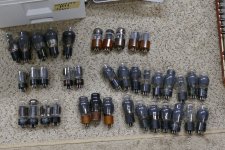
I have a bunch of old 6L6G's and GA's that I don't mind beating on, but oddly I haven't blown any up.
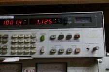
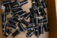
I have been collecting old metal tubes for building a guitar amp that I will call "MetallicAmp, all tube, no glass." My aim is to build a modern sounding high gain screamer with parts from before I was born (1952). So, what could Leo Fender have made if he didn't try to cut every corner he could? No mosfets, no silicon or germanium anywhere. No PC boards either. So far it only exists in the mind of the computer (LT Spice). Here I did test eight metal 6V6 tubes that I got in a box containing about 30 tubes for $5 at a hamfest. They all worked, and I'm not going to abuse them. They gave me 25 watts at 1.225% THD.
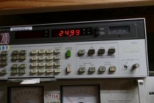
You mentioned the 6W6. The 6W6 spawned a bunch of tubes in octal, 9 pin and 7 pin variants. Here four crusty looking 25L6 tubes (a 25 volt 6W6) are being run on 350 volts plate and 250 volts screen. Power is 31 watts @ 1% THD. I have been to 400 volts on the plate but the tubes really didn't like it, but they are old and well used. This prompted me to buy 100 6DG6GTs from Stan for $1 each several years ago. Looking back it might have worked better on a lower screen voltage.
Some of the 6W6's and 6DG6GTs will be tested in the UNSET test amp soon. Right now my 100+ WPC 26HU5 UNSET test amp is being used to push my Yamaha NS10M Studio monitors around on the bench.
"What nobody batted an eye about implying running 6W6’s off rectified 120? Man, you guys gotta get with it"
Rectified wall is a starvation diet for the 6W6. Only cheap radio designers would do that. The 6W6 needs plate voltage but keep the screen below 175 volts and you can run lots of plate voltage. The 6CW5 is the same way.
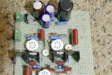
Stick a 50 volt 150 mA heater in a 6W6 and you have the 50L6. Cut off a pin, and shrink the remains to fit in a smaller radio and you have the 50B5 which became the 50C5. You know what it was intended to be used in and how it was powered......what a waste. One hot and hungry tube struggling to make 2 watts in class A SE. Feed it from a 120 to 120 volt isolation transformer (Triad N68-X) which is connected to another Tubelab exclusive, the "way too many diodes power supply." There are 9 diodes and 4 caps in this supply. It supplies rectified but unfiltered DC to the series heater string, 165 volts for the screen grids, and 335 volts for the plate supply and the rest of the guitar amp breadboard. The output tubes are 50C5's in a shrunken UNSET P-P configuration. The driver is a 12AU6. Power output is 20 watts at 3.76% THD. It ran at this power level for 9 hours without incident and still lives today.
"you CAN use Vg2 to effectively “match” the load impedance to a given power supply."
All of my "discovery" testing has a variable power supply on screen, plate and often other electrodes. I "turn the knobs" and look for best plate efficiency while keeping the screen dissipation within the published ratings in finding the limits for as given tube.
I have been collecting old metal tubes for building a guitar amp that I will call "MetallicAmp, all tube, no glass." My aim is to build a modern sounding high gain screamer with parts from before I was born (1952). So, what could Leo Fender have made if he didn't try to cut every corner he could? No mosfets, no silicon or germanium anywhere. No PC boards either. So far it only exists in the mind of the computer (LT Spice). Here I did test eight metal 6V6 tubes that I got in a box containing about 30 tubes for $5 at a hamfest. They all worked, and I'm not going to abuse them. They gave me 25 watts at 1.225% THD.
You mentioned the 6W6. The 6W6 spawned a bunch of tubes in octal, 9 pin and 7 pin variants. Here four crusty looking 25L6 tubes (a 25 volt 6W6) are being run on 350 volts plate and 250 volts screen. Power is 31 watts @ 1% THD. I have been to 400 volts on the plate but the tubes really didn't like it, but they are old and well used. This prompted me to buy 100 6DG6GTs from Stan for $1 each several years ago. Looking back it might have worked better on a lower screen voltage.
Some of the 6W6's and 6DG6GTs will be tested in the UNSET test amp soon. Right now my 100+ WPC 26HU5 UNSET test amp is being used to push my Yamaha NS10M Studio monitors around on the bench.
"What nobody batted an eye about implying running 6W6’s off rectified 120? Man, you guys gotta get with it"
Rectified wall is a starvation diet for the 6W6. Only cheap radio designers would do that. The 6W6 needs plate voltage but keep the screen below 175 volts and you can run lots of plate voltage. The 6CW5 is the same way.
Stick a 50 volt 150 mA heater in a 6W6 and you have the 50L6. Cut off a pin, and shrink the remains to fit in a smaller radio and you have the 50B5 which became the 50C5. You know what it was intended to be used in and how it was powered......what a waste. One hot and hungry tube struggling to make 2 watts in class A SE. Feed it from a 120 to 120 volt isolation transformer (Triad N68-X) which is connected to another Tubelab exclusive, the "way too many diodes power supply." There are 9 diodes and 4 caps in this supply. It supplies rectified but unfiltered DC to the series heater string, 165 volts for the screen grids, and 335 volts for the plate supply and the rest of the guitar amp breadboard. The output tubes are 50C5's in a shrunken UNSET P-P configuration. The driver is a 12AU6. Power output is 20 watts at 3.76% THD. It ran at this power level for 9 hours without incident and still lives today.
"you CAN use Vg2 to effectively “match” the load impedance to a given power supply."
All of my "discovery" testing has a variable power supply on screen, plate and often other electrodes. I "turn the knobs" and look for best plate efficiency while keeping the screen dissipation within the published ratings in finding the limits for as given tube.
Attachments
-
 P3730056.JPG410.9 KB · Views: 47
 -
 P3730053.JPG590.4 KB · Views: 47
 -
 P4010695.JPG520.8 KB · Views: 46
 -
 P1000582.JPG360.7 KB · Views: 40
 -
 P1000583.JPG367.9 KB · Views: 40
 -
 P1000586.JPG538.3 KB · Views: 45
 -
 P1000579.JPG280.3 KB · Views: 38
 -
 P1000578.JPG296.2 KB · Views: 46
 -
 P1000577.JPG217.3 KB · Views: 42
 -
 P1000576.JPG518.1 KB · Views: 43
 -
 P1000581.JPG363.8 KB · Views: 45
The whole idea with the 6W6s was to try to push a cheap radio design as far as it would go, not to get the most power a 6W6 can on optimized voltages. On those plate and screens (400 and 150) the 10JA5’s worked out better so that’s what ended up in that particular amplifier. Perfect match for OPTs originally for 7591’s. 170v plate and screen is a serious limitation, hence going AB2 to get more current out of expendable tubes. More likely to tolerate that g1 flogging if everything else is below rating. I’ve had plenty of radios and phonographs with 50L6 and their 7 pin equivalents over the years. Always held a special place in my heart. Doesn’t make any more sense than loving an old Phase Linear when I have Crest CA18’s in my PA rack but it does.
And as far as optimizing g2, I think we do the same thing for different reasons. To maximize plate efficiency, the tube and transformer need to become choke points simultaneously. Extra current capability isn’t used and just results in heating up the screen. Not enough you drop output voltage. Personally, I’d rather under utilize a tube than under utilize a transformer because the latter costs more (and I dont have as many of them on hand). One doesnt see that when using a lab supply, but when they have to buy the iron you do. It’s a carry over from the Soild state days when putting in an extra pair or two of MJ15024’s was cheap insurance against amp failure. Transformer costs and weighs the same either way. $12 a pair for the extra silicon (Used to be 6 to 8).
Old radios and discarded TV sets from the 1950's was what I learned on in the 60's. Most of the series string stuff was forgotten once I had collected enough power transformers from TV sets to build stuff with "real voltages."The whole idea with the 6W6s was to try to push a cheap radio design as far as it would go, not to get the most power a 6W6 can on optimized voltages. On those plate and screens (400 and 150) the 10JA5’s worked out better so that’s what ended up in that particular amplifier. Perfect match for OPTs originally for 7591’s. 170v plate and screen is a serious limitation, hence going AB2 to get more current out of expendable tubes. More likely to tolerate that g1 flogging if everything else is below rating. I’ve had plenty of radios and phonographs with 50L6 and their 7 pin equivalents over the years. Always held a special place in my heart. Doesn’t make any more sense than loving an old Phase Linear when I have Crest CA18’s in my PA rack but it does.
In 2011 an "opportunist" attempted to sell his guitar amp kit by bragging about it in the forums here. He proclaimed that nobody could build a better vacuum tube amp than his for less than $100, to which I replied "wanna bet?" This led to a third party proposing a challenge for people to design their best guitar amp using less than $100 in total parts using prices for new components from valid suppliers. That challenge is now a sticky at the top of the Instruments and Amps forum.
I'm sure that you and most people here know that the most expensive parts in any tube amp are the transformers. It also seems that any transformer automatically gets more expensive if the words "tube" or "vacuum tube" get attached to it. The ticket for a low cost power transformer is to find something that can feed a smallish tube amp that's not related to tube amps. Some users went the back to back doorbell and air conditioner control transformers, but I went with the venerable Triad N-68X isolation transformer and series string heaters. The 20 watt amp needed an 80 VA transformer though. OPT's were repurposed power toroids or 70 volt line transformers.
The 6W6 exists in heater voltages from 6.3 to 50 volts. It has been stuffed into 7 and 9 pin envelopes and with some grid pitch changes morphed into the 6BQ6GT and 6AV5GT sweep tubes which grew bigger over time.
"To maximize plate efficiency, the tube and transformer need to become choke points simultaneously."
Any given OPT will work best when driven by a low impedance source. The loss of performance at the frequency extremes is caused by low primary inductance, excessive winding capacitance and leakage inductance. The effects of these factors would vanish if the transformer was driven by source with zero output impedance. Of course, this does not exist, but we can reduce the output impedance of the output tube / tubes by several means. Running them in triode configuration or using plate to grid feedback (UNSET) to make them perform like triodes is the easiest path to a low drive impedance. I have been experimenting with combining UNSET with some feedback from the OPT secondary with mixed results. More experiments to follow.
There is an optimum amount of power for a given OPT - it is somewhat dependent on an end user’s goal but you can define it. The limit is due to applied voltage - either from a safety standpoint or how much distortion or frequency response error one is willing to tolerate. There is also a similar power utilization curve for the PT - the DC supply will drop according to how much current you pull off it. You can always keep the DC at full by only pulling 10% of rated power off of it, but to get anything useful you’re sagging 10 or even 20%. Choke input supplies actually sag MORE - you just don’t see it because it does most of its sagging in the first 10% of loading. Then it slows down but does not STOP sagging. It’s simply a different curve to work on. The load must be kept between X and Y amps, and you can quickly find X and your point of pain for Y.
There is an intersection between the curves of the two, given you have both in your hand. THAT determines the actual output power capability of the amplifier. You try to extract more, and the power trafo won’t give it. You need to figure out how much thermioinic capability to stick between the two to get best use out of both. The goal may or may not be “as many watts as possible” - it may be “best sounding amp possible” or “something I can crank to 15 indefinitely”. Those factors determine how close to that intersection point you actually decide to operate.
The power trafo may or may not have adjustment capability. If it’s off the shelf, no. It is what it is. If you have a core in your hand, you can determine what secondary voltage you want. But it will follow the same utilization curve - at X VA load it drops Y%. You can only make just so big an amplifier with it. Smaller is ok too, if you’re willing to commit the core and wire to the project. Making your own OPTs is not near as cost effective as proper materials to do it cost more than ordering one from Mouser or Edcor. For PTs I start by yanking one from a dead solid state device. Am I willing to spring for an Antek? Sometimes, but not all. Depends on the goals. I’ll luck into deals like those 120/480V 900VA monsters that I can extract about 350W out of, but that will happen less and less as the surplus houses fold.
I can see the attraction of the UNSET concept, as it still allows you to “dial in” the current capability of the tube to match the supply/OPT yet not requiring pentode operation to do so. Triodes have a unique sound, and people like them. But in raw form, with triode operation the tube’s power curve is fixed and you normally have to adjust the IRON to get different result. Fine, if you are willing to throw infinite funds at a given project. Most of us have limits either by budget or principle.
OP started all this because he HAD a transformer that looked like it might work as an interstage transformer, and said “Let’s AB2 some triodes (or triode-like) so I can go further up the utilization curve of my PT and OPT” . Presumably he’s already paid for it so additional expense is zero. I’m guessing the idea at have been looked at a long time ago, but the cost of an IPT was just stupid high. Good ones are, since typically they need the same materials and construction techniques as quality OPTs in order to get fidelity. The idea of using a power toroid there does hold water, given the right set of conditions. Keep the “secondary” voltage under 120 to keep it out of saturation distortion. Check. HF response is normally above their weight/price class so it’s at least worth trying. Check. DC balance? Maybe. Needs investigation. Drive from a low impedance source (Gainclone amp) ? Check. It checks enough boxes where it can’t just be dismissed as a stupid idea. Whether or not class B2 is even appropriate? That’s on the user. Personally I would AB2 by giving it a little bias.
I’m not always trying to get the “max” out of everything. In the Quest For Power over the last 40+ years I’ve acquired a whole warehouse full of “smaller“ parts - like 6w6’s and 200 VA trafos. To me it’s like playing with 2N3055‘s that I’ve pulled out of junked Lambda power supplies when MJL4281’s are a just Mouser order away and I usually have them in stock, for repairs and the “big” projects. I tinker around with that sort of stuff constantly because the big stuff takes a lot of time, at least some money, and more planning than doing.
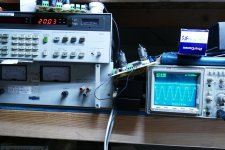
Anyway, just for the hell of it, last night I did a frequency response measurement of the toroid pictured in the first post. Put a 600 ohm load across the series 120V+120V windings and fed the 28V side so that 60VRMS came out the 120V+120V side. Power level was 6 watts. Could have gone much higher but i didn't have much in the way of dummy loads, and I wanted to see how low in frequency I could go. At the 6 watt level the transformer began to complain below about 13Hz. So anyway, here's the graph.
0dB at 1kHz
-1dB at 7.3kHz
-3dB at 14kHz.

0dB at 1kHz
-1dB at 7.3kHz
-3dB at 14kHz.
- Home
- Amplifiers
- Tubes / Valves
- Zero bias class B2 triode driver transformer