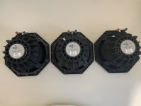
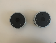
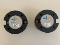
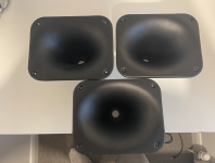
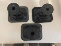
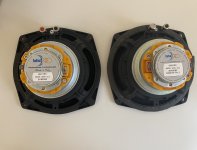
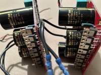
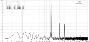
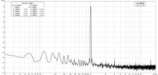
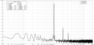
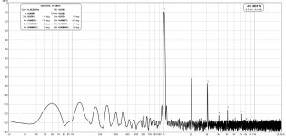
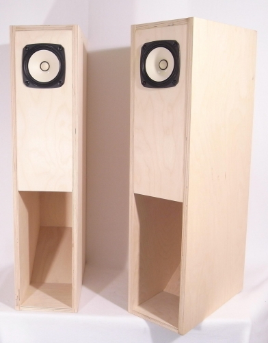
Evaluating Ripole with 3 LW150-4 6"

Hi there!

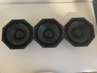
LW150-4 6" is not really a sub but there's some bass for my desk. I have 3 idle that I got a while ago, not something I just bought.

What people don't like about ripoles is good if you have them right in front of you. So I gave it a try and I'm liking a lot how it sounds, usually at 50cm from me. Just a prototype using the driver's box.

I wonder if I can use 3 of them for a small 4mx4m living room, listening 2.5m from it.

I was reading a recent thread about simulating a ripole with HornResp. I was wondering if you could model it as a 6th order bandpass. So I took some measurements 2cm from each opening and tried a simulation with the approximate data. It doesn't change much with small variations. I find it interesting that the peak is in the same place. 90Hz is the F3 for the suggested closed box.

Does it make sense to simulate it this way? Just wondering....

I can do measurements 50cm instead of 2cm from the openings later today, right now somebody else is sleeping in this room and I can not measure with more SPL.

1688808505698.png

1688808661683.png


This simulation has a 150 2nd order LP filter added. I think this amp I'm using now has this fixed crossover point set, from what I have measured in other tests.

1688808389320.png


The drive is inverted. No reason other than building fast.

A bit of black foam is separating the back of the driver from the cardboard, hard to see in the photo.


1688808126323.png
1688808216000.png


Model NumberLW150-4
ColorBlack
Unit of MeasureEach
UPC848791001864
Warranty - Parts5 Years
Warranty - Labor5 Years
Product Shipping Weight (lbs.)0.8
Speaker TypeWoofer
Nominal Diameter6"
Power Handling (RMS)40 watts
Power Handling (max)80 watts
Continuous Program Power--
Impedance4 ohms
Sensitivity86.1 dB @ 2.83V/1m
Frequency Response60 - 1,800 Hz
Voice Coil Diameter31.8 mm
Magnet Weight--
DC Resistance (Re)3.6 ohms
Voice Coil Inductance (Le)0.86 mH @ 1 kHz
Resonant Frequency (Fs)62.6 Hz
Mechanical Q (Qms)6.01
Electromagnetic Q (Qes)0.72
Total Q (Qts)0.64
Diaphragm Mass Inc. Airload (Mms)21.9g
Moving Mass Of Diaphragm (Mmd)--
Mechanical Compliance of Suspension (Cms)0.3 mm/N
Surface Area Of Cone (Sd)91.6 cm²
Volume of Displacement (Vd)36.6 cm³
BL Product (BL)6.52 Tm
Compliance Equivalent Volume (Vas)3.49 liters

Help! I stink!

I'm not sure if this is the right place for this. If not please move or delete. I have an old Luxman R-3045 I received a long time ago. When I received it the power IC's had apparently been blown and replaced at one time. The board is Bakelite and the burnt smell is that I really can't use it. It works very well as I have fired it up a few times and the sound is excellent. Now I cleaned everything with 99.9% alcohol with a scrub brush where I could reach and got the rest with a stiff bristle paint brush. and did it twice about a week apart with no noticeable difference. Does any one have a better solution to get the smell out of the board? Mike

Amplifier keeps blowing fuses

Hi. I am repairing a cheap blown amplifier which has two pairs of C5198 / A1941 output power transistors. It belongs to a friend of mine. Previous signs of a repair, someone soldered wires instead of fuses. A couple of 100 ohm 1/2 watt resistors, a 1/4 watt 1k ohm resistor, 2 x 5 watt resistors, A940 transistor, C2073 transistor, D669 transistor, 2 x C5198 2 x A1941 transistors were blown / shorted. The output transistors were shorted on all three pins, very bad since the wire fuses did not blow. I replaced all the damaged items. I failed to get the A940 and C2073 transistors, I got TIP41C and TIP42C, will they work? I also replaced D669 with BD139??? I tested it and it blew both fuses and 2 output transistors. I have tested everything, the bridge diodes, resistors, diodes, small transistors (5551 , 5401) all are fine. But somehow it keeps blowing fuses. There is one item I have not tested, an ic : upc1237 could it be causing this? Let me know. Thanks

Attachments

  • IMAG1369.jpg
    IMAG1369.jpg
    374.8 KB · Views: 132

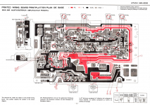
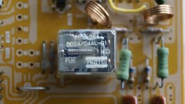
Speaker protection relay Fujistu replacement FRL-264 options

Looking for a replacement option in my Hitachi HMA-6500 amp and not able to get specs of the relay on the web. The relay is made by Fujitsu, FRL-264 and D024/04AL -01 are the numbers on the relay.

Omron/TE connectivity and few other vendors seems to have some options on Mouser and Digi key but I cannot figure which one will be a good option and some guidance will be greatly appreciated.

Attachments

  • _DSC9550.JPG
    _DSC9550.JPG
    264.1 KB · Views: 381
  • _DSC9551.JPG
    _DSC9551.JPG
    285.5 KB · Views: 319
  • hitachi-hma-6500-pcb-layout_771017.png
    hitachi-hma-6500-pcb-layout_771017.png
    903.4 KB · Views: 304
  • hitachi-hma-6500-schematic_771016.png
    hitachi-hma-6500-schematic_771016.png
    670 KB · Views: 364

MAS6116 oscillation

Gentlemen, I need your help.
The volume controller does oscillate at certain volume levels (and always near mute) ~3...4Mhz. Happens without signal, but does not happen when power amp is disconnected.
The MAS and OpAmp (OPA1656) have ceramic and electrolytic capacitors at power lines. Below is diagram from datasheet:

1687800645481.png


I did not install C213,C214,C217,C218. But I have 47 Oms R201, R202. Will 100p in feedback fix the issue?

Thanks in advance!

Service manual

Always into learning about audio, done some cabinet building, lotta guitar amp-related stuff. It's all good!
I recently received a AWA distortion meter F2423A, serial number 255 which has some problems. On the web the only service manual available is for serial numbers 586 and higher. And there clearly was an update in schematics, so I am stuck. i hope someone can help me out on this issue.

Moving not enough air. Adding membrane surface.

Hi people,

as it was my first try in DIY-Audio with small budget and mixed chances of success, I deceided to build rather small floorstanders, 2.5-ways driven fully active by chipamps. The drivers are two Gradient W130AL-8 for the midbass and a Peerless by Tymphany XT25TG30-04 ring radiator. Driven are the Chassis by three LM3886 chipamps.
I was really surprised, as the result of my efforts came out really nice, and it sounded, with the help of a subwoofer under 80Hz, for my uneducated ears, far better than expected.
As time went by, I noticed one thing which I didn't think of, when planning the speakers (because of a lack in experience): two 5.25" drivers with a linear max. of 2,6mm will not be moving really much air. Ok, they are loud (more than 50-60% is to loud) and they sound beautiful, but I cannot feel them. I realized this, when hearing such a mobile "boombox" (a bigger one ) and this thing made me feel the kicks of the upper bass in my stomach. Ok, I could build new speakers with 6.5 or 7" midbass, but a: expensive, b: no real tools (except of a router, which I got cheap from the supermarket), which means weeks of work.
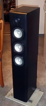
As I saw my actual Gradient midbass drivers on sale for half the price, I deceided to cut my speakers open. I'm still far from done, but today I put the drivers back in the first box, and I'm really excited about how they might sound. I expect nothing, as always, but I hope for a little improvement. The two lower drivers will play from 80Hz to 600Hz, the upper one from 80Hz to 2200Hz.. The Speakers measure H: 1048mm x W: 190mm x D: 300mm.
At the moment I'm at putting a fourth LM3886 in the back of the speaker, and I'm thinking about class-D. 4 channels with each about 80W should do it. What do you think?
(before/ after)

best regards
Jochen

Attachments

  • 800h.jpg
    800h.jpg
    91.3 KB · Views: 88
  • triple 800h.jpg
    triple 800h.jpg
    71.8 KB · Views: 88

Read the flipping data sheet properly

Started working on a new USB PC oscilloscope.
It uses a pair of A2D's and 50MHz PIC microcontroller.
I wanted to proceed slowly so I started off with channel 1 A2D IC fitted and it worked a treat.
I added channel 2 A2D and just got terrible noise.
The circuit looked fine to me.
Then spotted A2d on channel 2 enable was always low so making 2 A2D's data buses interfere with each other.
Turned out the A2D enable pin was also used as USB pin.
So disabled it as USB pin.
Still noise.
So back to datasheet on AD876 A2D.
Read it through slowly and carefully until I came across the tri state pin which enables databus output.
Then spotted delay from tri state changing state requires 150nS.
I was expecting just a few nS so that completely messed things up.
So moral of the story is read whole of data sheet first before using an IC.
  • Like
Reactions: rsavas

For Sale [FS] Components, Faital Pro, B&C, Hypex

Hey guys, I have several different components here for sale, pics to be added soon/upon request.

Faital Pro 8PR200 8ohm (3 available) - £180 for all 3
IMG_7338.jpegIMG_7339.PNG


IMG_7343.PNGIMG_7342.PNG

Faital Pro LTH102 horn (1 available) - £30
IMG_7340.PNGIMG_7341.PNG

Faital Pro 6HX150 (2 available) - £200 for both

Hypex FA123 (3 available) - £950 for all 3.

Prices do NOT include shipping. Shipping to EU also possible.
F6D51957-BFB8-4C28-B30B-F17331B5C34E.jpeg
EDB78C48-8641-4BA8-93C9-B019AD128DE2.jpeg

Attachments

  • 795771B2-7B50-4B5D-8E14-2B38E1D71568.jpeg
    795771B2-7B50-4B5D-8E14-2B38E1D71568.jpeg
    343.5 KB · Views: 275
  • 3C96E843-FE73-4634-9517-2972FC2D6A18.jpeg
    3C96E843-FE73-4634-9517-2972FC2D6A18.jpeg
    430.8 KB · Views: 296
  • Like
Reactions: Bas Horneman

For Sale Goldmund Telos clown boards

SOLD

Goldmund Telos clown boards fully assembled and tested

I am selling my 2 completely assembled tested boards of Goldmund Telos “clones”. I call them “clowns” because they are not a copy of the EBay copy attempt of the original Goldmund board. I have modified the EBay “copy “ this way:

  1. dual die output lateral mosfet (Alfet) instead of single. This allows only 4 transistors to mount per side which is more easier to implement than 8. All N channels come from the same lot tube. Same for P channels. Added they are double die then internally they cannot be better matched.
  2. Use of matched 2SK170Bl for input stage with current biased at about 70% of IDSS. This provides more “triode » sound this way. Refer to Pass Labs forum.
  3. Use of metal film resistors. Nichicon Muse B.P. caps for feedback.
  4. Use Mundorf caps for PSU. Psu caps and rectifier diodes on amplifier board. Very wide traces for PSU.
  5. pcb comes from EBay Jimsaudio and I must admit the layout and board quality is quite good.
  6. Output bias current adjusted for 500ma (125ma per single transistors).
  7. 100Wrms into 8 ohms (with +/-45VDC supply).
  8. Separate supply wires for front end circuit. I recommend about 7VDC higher than power supply output stage. Can also connect front end and power stage with same supply for simplification.
  9. THD is quite impressive for 1W to 100W. See curves taken this week just before dismantling the amp.
  10. Have been demonstrated with great success during a DIY activities with audiophiles/diyers. It sounds marvellous.
  11. I provide the modified schematics For reference since the boards are already assembled.
  12. Price for 2 tested assembled boards: 250$ USD
Fab

Attachments

  • A5B97CD5-D3EF-499D-98E2-2A4E73554620.jpeg
    A5B97CD5-D3EF-499D-98E2-2A4E73554620.jpeg
    640.1 KB · Views: 620
  • F29F070E-ACE5-42DC-A42E-436CF9D4B548.jpeg
    F29F070E-ACE5-42DC-A42E-436CF9D4B548.jpeg
    644.8 KB · Views: 607
  • 027CCCCC-D1A1-46D3-B17E-B15A37530321.jpeg
    027CCCCC-D1A1-46D3-B17E-B15A37530321.jpeg
    411.1 KB · Views: 600
  • Thelos_clown_THD_FFT_1KHz_100Wrms_8ohms.jpg
    Thelos_clown_THD_FFT_1KHz_100Wrms_8ohms.jpg
    130.2 KB · Views: 497
  • Thelos_clown_THD_FFT_1KHz_1Wrms_8ohms.jpg
    Thelos_clown_THD_FFT_1KHz_1Wrms_8ohms.jpg
    125.7 KB · Views: 394
  • Thelos_clown_THD_FFT_1KHz_10Wrms_8ohms.jpg
    Thelos_clown_THD_FFT_1KHz_10Wrms_8ohms.jpg
    127.7 KB · Views: 385
  • Thelos_clown_THD_FFT_1KHz_50Wrms_8ohms.jpg
    Thelos_clown_THD_FFT_1KHz_50Wrms_8ohms.jpg
    129.2 KB · Views: 372
  • Thelos_clown_THD_FFT_1KHz_25Wrms_8ohms.jpg
    Thelos_clown_THD_FFT_1KHz_25Wrms_8ohms.jpg
    126.6 KB · Views: 396
  • Thelos_clown_THD_FFT_1KHz_4Wrms_8ohms.jpg
    Thelos_clown_THD_FFT_1KHz_4Wrms_8ohms.jpg
    127.8 KB · Views: 495
  • Like
Reactions: smartx21

Anyone know what this insulator sheet is called?

I'm currently repairing my SoundStream Reference 1000sx amplifier and there is an amber colored, semi-transparent sheet that is sandwiched between the huge Darlington array, the power mosfets, and the amplifier's heatsink. I know it works as an electrical insulator and to allow heat transfer, but i'm having a total brain fart as to what the material is actually called. There was also white thermal grease on all the components to help aid in heat transfer.

I'm looking to either replace it with a new piece or if there is another, more modern material that transfers heat better, perhaps i'll use that instead. I already flattened the inner surface of the heatsink for better heat transfer and it currently has a 1200grit surface. So.... comments? Suggestions? Thanks in advance.

SVP and FVP preamp builders

Guys

Years ago i bumbled my way around anf FVP linestage. It did not work. It was sent to JoeR and he rescued it. It sounded great. I hardly used it though as life as a 20 year old can change so much.

In the last 12 months i moved from Sydney to a regional town and was blessed with a 5 car garage. So i started to get back into audio.

So the orivional FVP has been removed from service
I have now built a varient of the FVP and SVP with phono stages.

I varied it quite a bit using kandkaudio shunt reg and ccs. I have one per channel.

The SVP sounded a little better than the FVP. With either super reg or the kandk reg.

I ended up using 6922s in phono and 5687 in line. However i have found the 5687s that i have to be very microphonic and very very hot. I am about to try and make the linestage with 6922.

Apart from that i would like to talk to people who have made the phono stage. At the moment i am not happy with it. Relative to the linestage the phono is a little harsh and condensed sound stage. I am not sure i have it setup right. And the riaa has not been trimmed or tested. That is something i want to work on.

I also wish to just try other things and play with this circuit. I have buckets of 5842s, 5687 and 5670 even 5965. All bought 20 odd years ago. I even bought a couple of ec8010 to have a fiddle with. I might even look at an all tube MM phono.

I am also using a khozmo 50k attenuator but not sure if suitable. I do not know if it maintains a constant 50k across the range.

I would love some advice or shared experience on builds. I have read other guys posts and blogs mainly about the linestage but looking for more.

Anthony

Loudspeaker type and placement for my living room

Hello,
First post here! I arrived looking for info on line arrays. But let me explain my "problem".
Here is my living room/kitchen/office room in my flat (units in cm. 650cm is 31.3feet and 360cm is 10.8feet):
plan.png

Dashed line are walls which do not go up to the ceiling and there are no doors. So the kitchen is open to the living room and the office room.
The TV cupboard contains the amplifier + TV. Two bookshelf loudspeakers are on top of it at 1.7m/5.6feet above the floor, behind plants, rather close together ... OK not great

When listening to broadcast radio, mostly speech, the setup is OK.
We listen to music at moderate level: the sound comes from a single point and does not "fill" the room. In addition the sound is a bit dull, but after all this not high end equipment. We enjoy music much more in our car 🤣
When watching movies we all are off-axis relative to TV. Main complain here is lack of speech clarity (I am hard of hearing). We do not care about spatialisation/surround as we seldom watch blockbusters.

Ultimately the goal is to have punchy sound that fills the room at moderate level, the clearer the better, and the setup MUST have a high WAF. After all my wife got a lot of things right in this flat so I have to make an effort. Budget is 1k€/$. My ideas:
1/ make 4 to 6 3D printed satellites + 1 3D printed sub (like Hexibase stuff). The speakers would be placed along two walls of the living room (making an upside-down L shape). I can easily hide the cabling, the sub and some of the satellites. I would drive them with my current amplifier at first. I think this is the most appropriate solution in my situation but I know no-one with experience with that.
2/ buy one line array (such as JBL - CBT 50LA 1 in white) and stick it in the corner of the living room + 1 sub. The music experience may be fine thanks to the horizontal beam pattern. TV experience would suffer. I don't know where I could put a second array though. Will that "fill" the room?
3/ buy a soundbar and put it in the TV cupboard. I have read great things about Samsung soundbars including on this site. Problem is bars in the Q-series do not fit the cupboard 😢 . Also I fear they are best enjoyed when sitting right in front of them.

Traditional floorstanding loudspeakers are not an option: no place for them, too low WAF.

Well that's it. Sorry for the long post. Suggestions much welcome 🙂

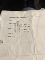
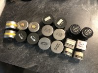
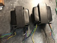
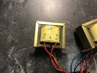
For Sale Sowter transformer for sale - 8 pieces

Sowter transformers for sale

8 pieces for $500 USD Shipped.

Payment by PayPal.

Check my reputation as a seller and contributor on Ebay, GroupDIY, DIYAudio and GearSpace (rafafredd username on all platforms). Buy with confidence.

Selling a collection of 8 pieces Sowter transformers. These are amongst the best transformers ever made for pro audio, on par with the vintage manufacturers like TRIAD, UTC or PEERLESS. Inductance values are amazing, with really low DCR!

Use this on your amplifiers, preamps or DACs for amazing sound and galvanic isolation benefits.

Or, if you are into proaudio, the 600:600 types are good for 1176 FET limiter input, discrete 990 type mic preamp, Spectrasonics mic pre, etc. The 10k:10k types are good for many Vari-Mu circuits, LA2A optical compressor, and nearly any ProAudio line inputs.

All tested and working!

Large size:

Sowter 3257 600 C.T. : 600 SPLIT (150+150)
Sowter 4791 600:600

Mid size:

Sowter 5937 10k:10k C.T.
Sowter 3575 10k:10k C.T.
Sowter 5153 600:600

Small size:

3x Sowter 5571 600:600

DM for details

IMG_20230709_203414_edit_350817955854281.jpg

IMG_20230709_203720_edit_350996948832378.jpg
IMG_20230709_203651_edit_351012856116230.jpg

IMG_20230709_203625_edit_351030273197478.jpg

Questions About Toroidal Transformer

hey guys, i have a toroidal transformer from a home theater which started blowing fuse all of a sudden.
i found a sticker on the top of the toroidal here is a image of it
.

it is 67W transformer
which has a input of 220v primary
and 3 secondaries which are:
15.5v-0v-15.5v which as thickness as


24v-0v
3.6.v-0v
the remaining above 2 secondary and primary has same thickness


question1: what is the amp for all the secondary?
i found out it can be calculated by W=VA
which gives
4.3225A
2.791A
18.6A for each which iam not sure that its correct!.
question2: is the thickness of the copper wire associated with the ampere?
question3: can i change the thickness of the copper wire by like .10mm or even like drastically ?
question4: is there any alternative way for solving the problem other than doing the trivial rewinding job ?
question5: if rewinding is the only way how many turns should i do and how do i calculate the number of turns ?

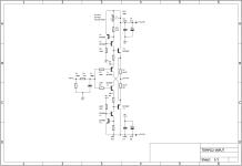
Micromega Tempo 2 'unofficial' schematics

Received one unit from a friend for fix on "no sound" issue. After replaced the open circuit current limiting resistors for the pre-amp power supply, now it works just fine.

Out of curiosity, as the amplification circuitry seems a bit 'complex', schematics are reproduced, as a reference for service or DIY build purpose.Only the input buffer and power amplifier section schematics are available.

Big thanks to @osexm, a forum member for his work on the Tempo 1 schematic as it lay a foundation for my reverse engineering work (both design almost identical). All I have to do is just 'double confirm' all the connection.

Some technical details for the Tempo 2:
-signal flow : input relays -> input buffer -> CS3310 -> CFA power amp -> output relay.
-the input buffer which is a diamond, look similar to HDAM-SA2, with different arrangement for the first stage CCS.
-fully DC-coupled from input till speaker output.
-extensive of BC550C/BC560C are used for the small signal section.
-lots of red Wima caps.
-Resistors are mostly 6-band E96 50ppm 1% tolerance, except for higher wattage application.
-standard issue LM317/LM337 are used for voltage regulator for input buffer and first stage of the CFA power amp.
-amplification+volume+dc offset detection circuit and control+other protection+display circuit are electrically isolated using optocouplers.
-dc offset, over temperature, rail fuse detection are available for protection and will display status (in case being activated) on the main VFD display( which is actually a CD player display!).
-speaker output relay does not offer turn-off delay(which actually not needed for Tempo 2, almost silence), but merely just cut-off the speaker in case protection kick-in.


t2in.png

t2amp.png
  • Thank You
Reactions: huggygood

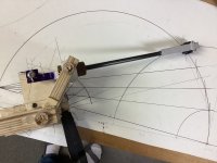
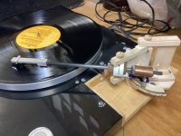
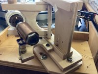
Tightly Strung

IMG_0184.jpegIMG_0185.jpegIMG_0191.jpeg

Stipulated: This is an exercise in wretched excess.

About a year ago, I built a string suspended TA which I have been using happily since. In discussions with Carlo (nocdplz), the possibility of a string suspended pivoting linear tonearm came up. I tried an experiment to see if a tensioned length of dyneema would support the weight of the arm without distorting badly. It did. I'd kinda hoped for failure.

A local hardware store carries small pieces of Baltic birch plywood for model airplane building, with excellent strength to weight characteristics, which was helpful because I can only do limited metal work in my shop.

The twin arm geometry is from several years ago and is posted in the "Angling for 90 degrees" thread. All of the pivot points are string - there are no bearings anywhere. The rear control arm is string/magnet/attractor.

The arm actually works well and seems happy with both low and medium compliance carts. It tracks accurately, doesn't skip, allows the cartridge to do its job and the resulting music is quite nice. I haven't done tests yet. The first will be for resonances, which weill narrow cart choice and also show how much difference there is between horizontal and vertical masses.

Doug

Piezo-Signal Amp

Hello everyone, newbie here.

I want to make an art installation, wheras piezo-plates are used to pick up the sound from plastic planes, on which they are mounted on.
The signal needs to be amplified for every small touch to be audible, and until now i've been using mic-inputs from my audio interface which worked fine. Now on a bigger scale i want more active piezos and i really think arduino pre-amp modules would be the way to go.

The sheer option and my lack of experience working with everything arduino are overwhelming. Which one's should i consider and what should i look out for? Every feedback would be greatly appreciated!!

Best regards from Germany.

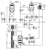
Borbely 6C33C-B Amp Build

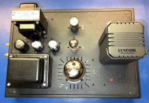
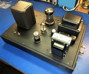
I recently completed a pair of mono blocks with Erno Borbely's 6C33C-B SE triode amp, using power transformers from Kenwood receivers and output transformers from Lundahl. I started the project more than 20 years ago. 🙂

A friend is testing one of them for me. So far it has a great square wave and produces 12.5W output across the entire 20 Hz to 20 kHz band.

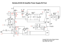
The power supply is a little funky so I have attached a schematic.

Attachments

  • 6C33C-B  side by side.jpg
    6C33C-B side by side.jpg
    639.1 KB · Views: 394
  • 6C33C-B Amp Top2.jpeg
    6C33C-B Amp Top2.jpeg
    688.9 KB · Views: 278
  • 6C33C-B Amp angled.jpeg
    6C33C-B Amp angled.jpeg
    641.4 KB · Views: 394
  • Borbely 6C33C-B.png
    Borbely 6C33C-B.png
    151.3 KB · Views: 453

Voltage across diode tube e.g. EZ80?

Hello,

I'd like to build the Mullard 3-3 amp:
http://www.r-type.org/articles/art-003h.htm

I'd like to omit the rectifier tube. But when I use an original power transformer from a EL84 based radio, and the greater voltage drop (from what I saw e.g. 40..50V) vs. silicon 4-diode rectifier is missing, the anode voltages will be too high.
Just adding a higher series resistance is not the same as the effect of a diode - in the former case, the voltage at the tube anode will more directly depend on the current going through it.

How would one do this?
... save from trying to obtain a transformer that gives just the right voltages. I might have another one, where the seller claimed it has curious 259V output, still a bit high vs. 250, but it's a start...

Then there's also the us having 230V today, where the transformers are for 220V, adding to what I need to reduce (if I don't want to age things prematurely).

Failing KT88- what to do?

Hello, was listening to some streamed music this afternoon. The amp is a Separo amp that has 4xKT88 ouut valves. I was doing my ironing when my wife came in and said, “what’s that smell?”. At first Ithought it was the iron but I looked across at the valve amp and on of the KT88s was glowing much brighter than the others. The sides of the tube were going black too.

The volume was inly at 10 o’ clock bit I switched the power off immediately. So what do I do now? Is it likely to be one valve failing or is it likely to be something else? If it is just the valve, can I just replace it with another KT88 of the same make (Genelux) ordo I need to replace all the KT 88s?

How do I proceed from here to see whether it is just the valve failing or possibly the transformer or something else? I’m reluctant to even turn it on again before I receive advice. Thanks all.

Which function generator?

At this moment I am testing a function generator from UNI-T, the UTG962E.
It has the advantage of having 2 output channels which parameters can be set individually.
I cannot detect the possibility to synchronize those 2 channels. For instance, I want to have
the possibility when changing the frequency, both channels will change to the new frequency.
Is there a function generator which can do this?

STV-4H AND STV-3H diodes array

Hi, On my schematic, in the bias section, there are those two diodes array. The STV-4H are represented by 4 diodes and the STV-3H is represented by 3 diodes. Is it really the case, if yes, what kind of diodes could have approx. the same temp variation. Or could it be replace with another thermistor having a PTC (positive temperature coefficient) that could be glue to the heatsink. If I replace them with standard diode like 4148 or 914, do I have to put 4 and 3 of them in serie. Thanks for any advice.

KSA250 mains Voltage conversion and a question about versions

Hi all DIY hifi lovers!

Just 2 days ago I have aquired an old Krell KSA250, sold as defective.
It turns out that the soft start board (mostly the capacitors on it) is toast. Working on that now.

I'd like to switch the unit from 220V ac to 240V ac. Could anyone help me with the correct position of the 2 switches for 240V ?

Also: Given the arrangement of the loudspeaker terminals, mine must be version 2 or 3. I have Googled a bit but can't find any information on the differences between the 3 existing versions.
It would be great if someone could lift this curtain for me.

Warm (when the amp works "hot"!) Regards from the Netherlands,


Jacques

Synergy/ MEH Horns and Port Length, size, form

Hi

I am planning my first meh horn.

What is clear to me is the position: position should be max lamda/4 from next diafragma of the tweeter and ports should be in the corner's.

But what about port size und port form? I found somebody who said: size max ~1/8 of SD is this correct?

In my case it could be necessary, to make the ports a bit longer and diagonal, to make sure, that i keep the max lambda/4 rule.

Is it OK to drill the holes not 90° into the plate?

I have attached a picture. The red part is a diagonal port. Frequency range would be 100Hz to 500Hz.

Thx a lot and greetings

Christian


Port.PNG

Hiwatt t40 problem bias e pointed Graetz

Hello everyone on the forum!
I am a new member and I write from Sardinia.
In my city there are few technicians and therefore I decided to "specialize" in repairs, even if I'm just starting out!
I find myself with this hiwatt t40 combo with numerous problems.
listing I don't have the negative voltage of the bias in pin 2 of the el84, so when I mounted a new set of el84 tubes I immediately noticed red plate.
furthermore this amplifier has a diode bridge on the filaments which tends to get hot.
I honestly don't understand how it was designed or at least this is very ambiguous.
Since the wiring diagram is not available and they never reply on the hiwatt.uk site, I ask you for a huge help.
I find myself in the position of not being able to repair this amplifier.
I tried to follow the diagram to have a logic, but I don't know why there is no negative voltage of the bias and because the graetz point heats up so much.
thanks if you can.
Sorry for my english.
Caesar

LM1875T TO220 -LF02, -LB03 et cetera which one to buy

There are 6 different LM1875T listed on Mouser including in stock: LF05,LB05,LF02,LB02,LB03. Please help me find the meaning of these suffixes.
The LF05 has .005% less THD than the others. They vary in price. These factors don't matter for this order.

I soldered a strip board with LF02. It worked well with single 19vdc supply. Now I working on a tidy version.

Help me with my first build WWMTMWW

Hi, I have started my first speaker build and would like some help.

the idea looks like this, the speakers will be big, 4-ways, they will have active crossing with built-in final stages from icepower.
the construction will look like wwmtmww

the speaker elements that I currently have are:

2x Tweeter: Vifa XT-19 4
4x midrange: Dayton audio RS100 8
4x Midbass: Dayton audio RS225 8

I would like to have subelements that cross roughly around 60-70. I have been looking at the dayton audio RS210 HO/HF. How would two of those work in this setup?

How does the whole idea seem in general? disregard the cost issue, it has no bearing in this case. What I'm interested in knowing from those of you who are pros in the case is if it works?

My concern with the sub elements is that the sensitivity is so different to the other elements, how do you compensate for this?

sorry if the english is a bit weird, i had to use google translate.

Noob oscilloscope analysis needed

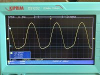
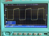
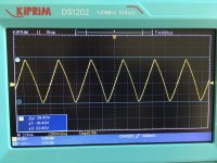
Hi, I got my new oscilloscope up and running. Tested the Vac with an 8ohm dummy load resistor. Made some basic measures and took screen captures (see below).

1. The first image is a sine wave (1Khz) at about 0db (from the AVC) and as you can see, the bottom of the wave is doing something funky.
2. 2nd image is the same input/output levels except a triangle wave form
3. 3rd image is the same input/output levels except a square wave form

My system is a streamer (2V output) --> autoformer volume control --> amp. The sine wave form is clean until about -3db on the autoformer, then the bottom of the wave starts to flatten (as evidenced in the image #1). As the autoformer volume control moves up to a maximum of +5db, the bottom of the sine wave form flattening gets worse. So, I need help interpreting these images. Is the issue with the power amps, AVC or streamer?

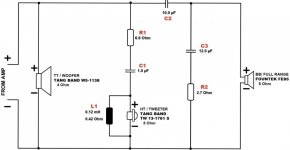
Schematic of my amp is attached. This is the 35T SPUD/OTA experiment that I am running. BTW: the sound is wonderful at low and medium loudness. But once the AVC is at -3db thru +5db, the sound gets distorted. This correlates with the scope measurements. I am getting a 14K OPT to replace the 5K OPT, as this should help the bass which appears to be much of the distortion.

Any input would be appreciated.

Attachments

  • IMG_1271.JPG
    IMG_1271.JPG
    456 KB · Views: 113
  • IMG_1273.JPG
    IMG_1273.JPG
    448.5 KB · Views: 77
  • IMG_1272.JPG
    IMG_1272.JPG
    478 KB · Views: 95
  • ss 29.png
    ss 29.png
    133.6 KB · Views: 114

For Sale Assembled Pit Viper Crossovers

Hey folks, I have some ready to crossovers for the Pit Viper speakers by Paul Carmody. The PCB's were made by Matt G (you all know the one, what a great guy). I made some modifications to my driver layout that unfortunately proved to be a little too much for the crossover and haven't had luck altering the xover parts to appease my layout.

I'll ship them to your door for $60.

20230622_183815.jpg

Hybrid RIAA tube preamp SS Poweramp General Arrangement

Hi,

Could someone please confirm what the big picture general arrangement to drive a pair of SS Icepower Monoblocks with a tube preamp from a turntable phono signal? Looking to only use tubes and no solid state up until the poweramp input. Assumption; SS Amp has 10K impedance so preamp requies <1K impedance.

Example 1. - Preffered but cannot find design
Phono MM or MC cartrige > Class A Single End Tube Preamp (impedance <1K) > SS Monoblocks (10K impedance)
Can anyone recommed any Class A Single End preamp designs with an impedance of less than 1k that accepts a RIAA input?

Example 2.
Phono MM or MC cartrige > RIAA Tube Preamp > SS Monoblocks
such as http://diyaudioprojects.com/Tubes/RIAA-Phono-Preamp/

Example 3.
Phono MM or MC cartrige > Tube RIA converter > Class A Single End Tube Preamp > SS Monoblocks
I found this design but I think it does not accept a RIAA phono input
https://www.cascadetubes.com/the-12au7-cathode-follower-color-preamp/

For Sale Some brand-new old stock aluminum electrolytic capacitors SMD

Hi All ! Long time to see.😆
1、315V 330uF 30x35mm 105C Snap In Capacitor Lelon LSK331M2F--A3035(50pcs)
https://www.ebay.com/itm/234973151726
2、50V 470uF 16x16.5mm SMD Capacitor Lelon VEJ471M1HTR-1616(200pcs)
https://www.ebay.com/itm/234976089271
3、25V 100uF 8x10mm SMD Capacitor Lelon VEJ101M1HTR-0810(500Pcs)
https://www.ebay.com/itm/234976105848

Zobel Network?

I'm not going to pretend that I really understand this subject, but I'm intrigued by the idea of Zobel networks and would like to learn if it would improve my speakers, which are currently leaning toward a harsh top end.
They are small T-M-M towers, with the 25mm silk dome CSS LD25x XBL tweeter above a pair of CSS LDW7 7" midwoofers, crossed at 1800Hz. Crossovers have good quality components by Erse and Jantzen.
Actual construction of a Zobel network seems pretty simple, but I don't really understand how to design one that's right for my speakers. Can anyone help?
Thanks!

Ideas for horn subwoofer (B&C 12PS32)

Hello everyone!.. i have this driver (b&c ps32) and i am thinking of building a sub ,specifically a horn type. I have built mth30s in the past, with great results, using ps32's smaller ''brothers'' the pz32's. I have seen martinsson's roar 12 sub plan, i find this very interesting design. I have done some reading and it seems that this design have some opposers , maybe it needs sove development maybe not, so it can reach the success of the mth30 or the tham 12, tham 15. I am open to ideas of course, since this site is a huge tank of knowledge with people that they really love what they do. thanks in advance and KEEP BUILDING....
12ps32-8_1.jpg

No more blue glow in Australia

I am writing this for the benefit of any Australians using this forum. It is now illegal to own sell mercury vapour tubes including 866 and 83 rectifier tubes in Australia. Included is a picture of a tube I handed in today, 17 tubes were sent to Northern Adelaide Waste Management, many of the tubes were brand new. Also included is a notice from a radio club magazine.
ug scale.jpg

mercury b.png

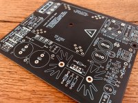
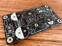
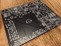
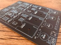
FS PCB clearance: Headphone Amps, D-Noizator PSU, MOD output delay, Ground Isolator..

I have a few spare PCB's. These are extra boards which I have left over from a fabrication run (due to minimum order requirements) and are therefore sold for DIY purposes only and not for commercial gain. They are to cover board, build and shipping costs to me, not for profit. Once they are gone, they are gone.

PAYMENT AND SHIPPING:
  • Payment by Paypal "Friends and Family".
  • UK - Free untracked P&P for orders over £5, additional fee for Signed-For.
  • EU / USA / Rest Of World - As per Royal Mail: Get a price | Royal Mail Group Ltd, additional fee for tracked.
  • Payment within 48 hours before being released from reserve.
  • Please reply here followed by a pm if interested.


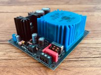
Die-Noizator 5-36V Linear PSU, PCB designed by me, schematic by Elvee/diegomj1973
D-Noizator: a magic active noise canceller to retrofit & upgrade any 317-based V.Reg.
Single rail positive PSU 5-36V.
Onboard transformer solution (Talema/Amveco/RS Pro toroidal series).
EMI filter, transformer snubber, CRC, LM317, Sziklai Pair Die-Noizator. Extremely low noise PSU.
These are my latest revision (2.1) with compatibility with 110V or 240V mains voltage.
Transformer secondaries can be jumpered parallel or series.
None available £7 each, 100g 'Letter'
  • 2x kcom00 (AUS) Dispatched 20th August
  • 2x jimk04 (UK) Dispatched 20th August
  • 2x mgb1965 (GER) Dispatched 20th August
  • 1x sq225917 (UK) Dispatched 7th September
  • 1x Mituisho (UK) Dispatched 13th September

Die-Noizator 5-36V, PCB designed by tombo56, schematic by Elvee/diegomj1973
D-Noizator: a magic active noise canceller to retrofit & upgrade any 317-based V.Reg.
Single rail positive PSU 5-36V
Offboard transformer.
None available £4 each, 100g 'Letter'
  • 2x kcom00 (AUS) Dispatched 20th August
  • 1x kffern (AUS) Dispatched 20th August

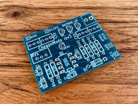
Objective 2 Headphone Amplifier designed by NwAvGuy
NwAvGuy: O2 Details
7x available £8 each, 100g 'Letter'


Passlabs ACP+ Headphone / Pre-Amplifier Clone, PCB designed by withmatt
Amp Camp Pre+Headphone Amp - ACP+
None available- £12 each, 200g 'Letter'
  • 1x mgb1965 (GER) Dispatched 20th August
  • 1x Peppe (SWE) Dispatched 1st September
  • 1x Piisami (FIN) Dispatched 1st September
  • 1x M_Balou (GER) Dispatched 1st September
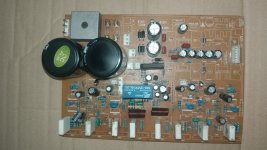
MOD: Mini Output Delay for Headphone / Line-level Audio designed by me
MOD: Mini Output Delay - a headphone / line-level audio output delay retrofit PCB
A miniature 2x3cm retrofit board to protect headphones from turn-on/off power transients.
12-35V power input. 0-30 seconds adjustable delay time.
10+ available £4 each, 100g 'Letter'
  • 2x mgb1965 (GER) Dispatched 20th August
  • 2x Gregje (UK) Dispatched 10th September
  • 2x Mituisho (UK) Dispatched 13th September
  • 2x SigFire (GER) Dispatched 21st September
  • 4x s666foto (NED) Awaiting Payment

Ground Breaking: Earth Loop / Audio Ground Isolator designed by me
A 2x3cm board that helps reduce hum in audio circuits that are attached to a mains earth connection.
x5 available £3 each, 100g 'Letter'
  • 2x kcom00 (AUS) Dispatched 20th August
  • 5x truepaul (USA) Dispatched 26th August
  • 2x Neat Ripple (UK) Dispatched 28th August
  • 2x Slinkymalinky (UK) Dispatched 4th September
  • 2x avinunca (UK) Dispatched 5th September
  • 2x sq225917 (UK) Dispatched 7th September
  • 2x Mituisho (UK) Dispatched 13th September
  • 2x SigFire (GER) Dispatched 21st September

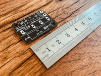
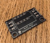
Alps RK27 Blue Velvet Breakout / Mounting Board designed by Nisbeth
A breakout board for mounting Alps RK27 volume potentiometer.
10+ available £3 each, 100g 'Letter'
  • 2x Neat Ripple (UK) Dispatched 28th August

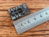
8-Pin SOIC or MSOP/(T)SSOP to DIP Adapter
A miniature board to mount SOIC or MSOP/(T)SSOP integrated chips into DIP sockets. Perfect for op-amp rolling.
10+ available £2 each, 100g 'Letter'
  • 2x mgb1965 (GER) Dispatched 20th August

CheapModo Snubber Calculator designed by Mark Johnson
CheapoModo: quick and dirty transformer snubber bellringer jig
A quick and dirty transformer snubber bellringer jig to calculate optimum snubber resistance values.
None available £4 each, 100g 'Letter'
  • 1x kcom00 (AUS) Dispatched 20th August
  • 1x M_Balou (GER) Dispatched 1st September
Attachments

  • IMG_7980.jpg
    IMG_7980.jpg
    1,005.2 KB · Views: 930
  • IMG_8011.jpg
    IMG_8011.jpg
    816 KB · Views: 907
  • IMG_7982.jpg
    IMG_7982.jpg
    990.8 KB · Views: 889
  • PCB-O2.jpg
    PCB-O2.jpg
    989.7 KB · Views: 866
  • IMG_7984.jpg
    IMG_7984.jpg
    886.3 KB · Views: 838
  • IMG_7995.jpg
    IMG_7995.jpg
    813.3 KB · Views: 303
  • IMG_7986.jpg
    IMG_7986.jpg
    945.5 KB · Views: 292
  • PCB-RK27.jpg
    PCB-RK27.jpg
    638.1 KB · Views: 303
  • IMG_7991.jpg
    IMG_7991.jpg
    459.2 KB · Views: 308
  • IMG_7997.jpg
    IMG_7997.jpg
    957.3 KB · Views: 302

OB mono

...any of you use a mono OB speaker in your regular system? How do you think it compares to stereo OB or stereo box speakers?
I want to build a speaker similar to Reflector Audio P18 (but with a coax in place of the 2" compression driver). Two of those and the associated active amps and cabling would be unbearable in the living room. But just one is doable 🙂🙂🙂

Attachments

  • images.jpeg
    images.jpeg
    27 KB · Views: 68

mid/bass driver with dual voice coil?

I'm pretty new to higher end stuff 🙂 I have a pair of Energy Veritas 2.2 which have dual voice coils in each 6.5" woofer. The woofer is 3db down at 40hz (ported cabinet) and crosses over to a 2" aluminum dome midrange at 550hz. They are pretty transparent in the mids (edit: including the lower midrange spectrum that's covered by the woofer).

I'm planning on running them with a servo sub, crossed over at 80-85hz. The two voice coils are connected internally, so there are two wires brought out to connect to the crossover. Dual voice coils are supposed to help lower distortion at low frequencies and are used in some subs. I've seen dual VC midrange units for high power car audio, but I haven't found anything yet in the mid-high end audiophile market.

Here are a few details in a review of the Veritas 2.4 (3 of these mid/woofer units) from https://www.soundandvision.com/content/energy-veritas-v24-surround-speaker-system:

"The Veritas V2.4's 6.5-inch woofers have dual voice coils wound in opposite directions (thus the designation Dual-Hyperdrive). Each coil is situated in its own magnetic gap; operating them in tandem is said to significantly reduce distortion. The cone is made of a special composition designed to optimize weight, stiffness, and damping. A phase plug of solid aluminum eliminates the dustcap—a possible source of coloration—and helps dissipate heat."

So would a dual voice coil setup also improve the accuracy of the lower midrange? Or is it just mainly for the bass region?

For Sale Transformers!

Cleaning out the shelves:

2x Power tranformers: Prim 115/230, sec1 300-0-300, 300ma / sec 2 5v, 3A / sec 2 6.4V 4A. SOLD
2x PP Output transformers for EL34/6l6, 30W, 5k6 into 16/8/4ohm. Brand unknown. SOLD
2x Amroh U72 SE output tranformers. 5k,7k into 5/3.5/2.5 ohm, max 80ma,SOLD
2x Interstage transformers, 1+1:1+1, no further info, 60€/pair
2x input transformers, 0-30-ct-250-600 into 10k-0-10k, can be used as input transformer or totem step up or step down, 60€/pair
6x Toroidy transformers: All 20VA/ 2x 11V, 1x11V, 2x 25V, 2x18V, 2x11V, 2x15V SOLD
2x Sowter 4652 Line output transformers, 150+150:150+150, SOLD
9x pairs of input/mic transformers, some info included, make me an offer!

Will ship worldwide

Attachments

  • IMG_3300.jpeg
    IMG_3300.jpeg
    296.8 KB · Views: 142
  • IMG_3301.jpeg
    IMG_3301.jpeg
    286.4 KB · Views: 144
  • IMG_3302.jpeg
    IMG_3302.jpeg
    352.3 KB · Views: 132
  • IMG_3303.jpeg
    IMG_3303.jpeg
    411.9 KB · Views: 131
  • IMG_3304.jpeg
    IMG_3304.jpeg
    237.8 KB · Views: 191
  • IMG_3305.jpeg
    IMG_3305.jpeg
    595.2 KB · Views: 211
  • IMG_3306.jpeg
    IMG_3306.jpeg
    412 KB · Views: 205
  • IMG_3307.jpeg
    IMG_3307.jpeg
    382.6 KB · Views: 166
  • IMG_3308.jpeg
    IMG_3308.jpeg
    587 KB · Views: 173
  • IMG_3312.jpeg
    IMG_3312.jpeg
    567.2 KB · Views: 156
  • IMG_3313.jpeg
    IMG_3313.jpeg
    494.7 KB · Views: 143
  • IMG_3314.jpeg
    IMG_3314.jpeg
    588.7 KB · Views: 152

What’s this Amps 8 ohm RMS? Help

8CE57182-369E-44A3-8C39-1976682C3397.jpeg

I got this amp it’s says 1200w Max blah blah…

The actual rms is 2x

200w for 2omhs

I got a sub coming that’s 200rms 400max
It should be fine, the amp got 2 speaker outputs and it’s 2-16omh amp, could I run my sub from one speaker output and my 4x30rms watt 3way coaxial 4omhs speakers from the second channel?

Running the coxial speakers at 8omhs will make them take 60rms, just not sure can’t find the amps 8omh load rms but am guessing from the image above it’s somewhere 70watt at 8omh

Please correct me if am wrong

This is for home project I already am running my coxial speakers with a cheap amp.

Could I have blown a channel?

Hi All, been installing an Audison F8.9 DSP/Amp into a car and had to tap into the output/speaker cables of the OEM amp, to feed to the DSP, and all went well until replacing the factory OEM speakers, when i realised the wiring was different colours at the speakers compared to what i had tapped into at the OEM Amp side.

I had the negative battery terminal removed, and the speaker output plug removed from the OEM amp, and checked continuity between the speaker wires at the doors and the wires i had tapped into at the OEM amp side, to establish what colours at the OEM amp side were connected to what colours at the OEM speaker end.

However i was getting some strange readings, as was getting continuity tones from more than one set of speaker wires, and then i realised that I still had the speaker output cables plug leading from the DSP/amp still connected, i therefore removed that and all was fine with continuity as you would expect, with continuity only on one wire at the speaker and one wire at the OEM amp side, therefore it must have been the DSP internal circuity that was causing the strange readings/continuity on more than one set of speaker wires.

Anyway, my question is, even though i was checking continuity between the speaker wires at the OEM amp side and door speaker wires, because i still had the speaker output plug connected at the DSP/Amp, could i have blown a channel whilst checking continuity on those speaker wire outputs whilst they were still connected to the DSP? As essentially i've sent voltage up the output line?

Sony STR-6045 Diagnostic - help needed

Hi guys,

Lately, I have developed some interest in electronic repair and fixed a Celestion Ditton 662. But I wanted to learn more and my current project is now a small amplifier from the 70's, the Sony STR-6045.

When I purchased it, it had no power and a blown fuse on the Power Supply Board (a soldered one). I took the following steps to resolve the problem and I have some newb questions that I hope won't generate too many responses like "if you don't know electronic, hire a professional or go take some lessons online first". This is a hobby, I just want to learn.

1. I verified every components on the PSU board by unsoldering the necessary legs and measured resistors, diodes, capacitors and transistors. All were good except a 47uf capacitor that was 34% over specification. Any way, I changed the 3 electrolytics since there were not many and they were so old.

Question 1: The service manual seems to indicate that electrolytic capacitors can be 100% over specification. Is this normal and true?
Sony_STR-6045_capacitors_tolerance.png


2. I also cleaned the board heavily with alcohol and acetone as it seems to have oxidation or flux that were never cleaned up.
PSU_Board_Conductor_side.png


3. While everything was disconnected, I measured the voltage at the secondary terminals of the power transformer: 54.6 vac.
Question 2, is this normal for such and amp? The service manual does not specify what it is.

Sony_STR-6045_specifications.png


3. I put it back together and powered on the system (using a dim-bulb tester). Got a big shiny lamp. Half success. My diy current limiter is working but the amp is still not!

4. I then disconnected all wire except those going to the power transformer. And this time no light. And I then tried to measure the voltage as shown on the service manual.
Very stupid Question 3: How do I do this? I tried to clip the black prob to the chassis and to prob with the red one at the indicated points. I could not get any significant voltage.
Sony STR-6045 PS Board - Components Side.png

Sony STR-6045 PS Board - Conductor Side.png


5. Because there was no short when the power amplifier board was disconnected, I thought the problem was further down on the power amplifier board. But while trying to measure voltage it started to make smoke! R806 being super hot.
Question 4: Is it because I should have left the connections to the filter capacitors or is there a problem with the board I have repaired?

The full service manual is available online at many places (here for instance) for those interested although the scan is of poor quality. Here is an excerpt of the schematic diagram - power sections.

sony_str-6045_sm_power_sections_200percent.png


Thank you all in advance for your valuable advises.

Field Coil vs Ferrite Magnet sound

Hi All,
Ever since I started fiddling with FR speakers, I've been reading on how good FC FR sounds
& this has gotten me very curious. Like SET Amps, FC speakers are also from yesteryears.
Yes I understand the principals of how FC works & their flexibility in the adjustment of magnectic
strenght which offcourse would affect it sound production. My question is what if we adjust the
magnetic strenght of the FC to equal that of a same speaker but with Ferrite magnet instead, will
the FC still sound better & if so would it be due to coil design etc ?
By going FC this opens another can of worms which I've read the PS is very important to SQ as well,
so what is the proper type of PS is used to attain optimum results assuming that FC speakers are low voltage
version.

Many thanks

  • Locked
Help with hum in parafeed headphone amplifier

I recently completed a build of a Parafeed headphone amplifier, and have some hum that I would like to try and resolve.
There is a fairly long thread where I explored various options for a 5842 based amps but ended up with a 6C45Π similar to the Bottlehead Mainline and/or Papa Rusa.

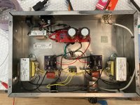
The circuit is pretty much the Papa Rusa, with the exception of using the DN2540N5 cascade CCS from SY's ImPasse/HMN designs, and paying some more attention to the AC heater wiring such as elevating to 50V above ground, using a 1nF ceramic cap to chassis and tying each node though a ~100ohm resistor.
The PSU is 220uF - 5H - 220uF. There is a 1kΩ + 1nF snubbers for the transformer secondary.

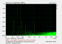
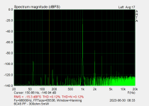
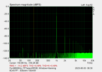
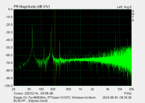
There is low (but audible) hum when there is no signal. Based on FFT, it is 60Hz and 180Hz (with lesser of 120Hz and 300Hz)
When there is signal, even fairly low amplitude, the 60Hz drops, so its not audible when music is playing, but I'd like to try and get it to a completely quiet background.
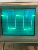
I also looked at it with a scope with a 10khz square wave and there doesn't seem to be any oscillation. The tilt of the sq. wave aligns with the FR measurement from ARTA (HF boost), but I am fairly novice when it comes to interpreting this.

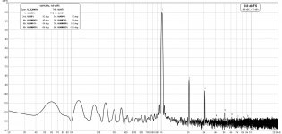
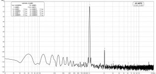
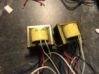
The attachments are FFT at 0 output, 5mW and 100mW, and FR at 0 output and 5mW output.

Any ideas where to look?
I'm also curious to understand why the 60Hz component drops when there is signal.

Thanks!

Attachments

  • 6C45 - 300ohm - 0mW.png
    6C45 - 300ohm - 0mW.png
    19.5 KB · Views: 88
  • 6C45 - 300ohm - 5mW.png
    6C45 - 300ohm - 5mW.png
    18.6 KB · Views: 82
  • 6C45 - 300ohm - 100mW.png
    6C45 - 300ohm - 100mW.png
    18.2 KB · Views: 86
  • 6C45 - 300ohm - FR - 0mW.png
    6C45 - 300ohm - FR - 0mW.png
    20.2 KB · Views: 81
  • 6C45 - 300ohm - FR - 5mW.png
    6C45 - 300ohm - FR - 5mW.png
    17.2 KB · Views: 106
  • 2023-06-29 15.23.05 (edited).jpg
    2023-06-29 15.23.05 (edited).jpg
    575.5 KB · Views: 101
  • JX2gTExY.jpeg
    JX2gTExY.jpeg
    355.2 KB · Views: 114

FS: Lot of drivers FE83NV, W200, 10FE200, Peerless Middomes; Audax PR240; Oberton 10M150; B&C 320K/C etc.

Selling the following:

Lot of various drivers in single listing -- Faital FE83NV Pair, Visaton W200 Pair, Faital 10FE200 single, Peerless Middomes: https://www.ebay.com/itm/275893316036

Audax PR240M0 8ohm 10" Sub woofer / Woofer Single: https://www.ebay.com/itm/275893307765

Oberton 10M150 8ohm 10" Midbass Bass Speaker: https://www.ebay.com/itm/275893297252

B&C 320K/C-A 8ohm 12" Bicone woofer: https://www.ebay.com/itm/275893304981

ChatGPT designed a gain cell - your comments?

LOL, so I got this apparently stupid idea to only do what ChatGPT suggested, I was not allowed (my own rules) to modify or add anything that ChatGPT did not suggest or recommended. The reason for saying apparently stupid is that I think it took about 3 weeks, on and off. The below description does of cause not contain all the tedious work it was to get it to understand what I wanted, sort out its many errors (talking about shielding where it suggested a garden fence because it shields for the wind). 🙂

Here is what I asked for and why it may look as it does.
1) Sound quality is most important.
2) Analog all the way. (just to avoid the usual digital volume control)
3) Possibility for adjusting the volume without ever using a pot.
4) Sound degradation is not allowed due to mechanical wear.
5) Everything has to work at the same voltage (It ended being +/-18VDC).

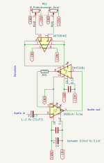
I started out asking for an op-amp, and it started by suggesting the OPA627, that I accepted but still did I ask about if it was the best, just to see how it reacted, it ended up in ChatGPT suggested a discreet solution and yes that is of cause a better solution, but I did simply not dare to begin letting ChatGPT guide me through a design of a discrete op-amp. (lol, my sanity is too valuable for that.) So I asked if there were some ready build op-amps, and it ended suggesting Sonic Labs 990Enh-Ticha that I have never heard off but hay it has great marketing.

Now to a way to adjust the volume and I asked it for a solution, again did several digital solutions come up, but I reminded the AI about the 100% analog solution. Then did it suggest using a FET, a combination of LED and LDR, or a gain cell solution. As you properly can read from the title did, I chose the gain cell to see how it would turn out.

To adjust gain did the AI suggest using a pot, but I reminded it about the possibility for adjusting the volume without any pot, and it got the AI to suggest a resistor of unknown value and a VCR in the feedback, but it was fairly limited what it could find and finally did it suggest a THT THAT2181.

Lastly after the AI had talked about using a pot for the 879th time did I ask how it would implement a pot, thinking of my rules about sound quality and wear, it had two suggestions, one was to get the best most expensive pot I could get or placing a buffer between the pot and the VCR, so I tried.

The result do you see below. It looks very strange, but this is how ChatGPT would have me build it.
Any comment? 🙂

Attachments

  • gain cell.png
    gain cell.png
    11.9 KB · Views: 402

JL Audio E6450 Q1 &Q2 part numbers

Hello guys, working on an E6450 with burnt P/S FETs. Found transistors Q1 and Q2 in the driver circuit are blown. The part number starts with PN, but can’t make out the complete part number. Anyone knows the correct part number? Thanks

Attachments

  • 406352C3-F68D-45C1-A4ED-F77E81970552.jpeg
    406352C3-F68D-45C1-A4ED-F77E81970552.jpeg
    722.2 KB · Views: 87
  • 1BFBA1FA-6CBB-459E-89D9-C5871AC7F57C.jpeg
    1BFBA1FA-6CBB-459E-89D9-C5871AC7F57C.jpeg
    520.8 KB · Views: 85

Wharfdale Centre 8 - 5" kevlar speaker specs

Hi

I have a Wharfdale Center 8 with the yellow 5" kevlar woofers and I was wondering if anyone has either in thier possession or a link to, the mechanical and electrical specs for these drivers, I was wanting to repurpise them into a 3 way speaker project and need specs to design an enclosure.

I've done some Web searches and come up with nothing.

The other option is to take the existing box, which is single ported and split it into two enclosures, how can this be calculated and achieved?

Adam

Acoustical notch filter for TPL-150

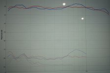
TPL 150 in dipole the 2º harmonic distortion drops 20dB, but have a big peak in the 8kHz range frequency response.

You can see in this tread:

https://www.diyaudio.com/forums/multi-way/142015-baffle-dipole-beyma-tpl-150-a-9.html#post1993491

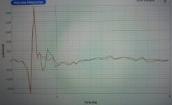
You can see in the green impulse response a double oscillation. The period coincides approximately with 8 Khz. peak.

8 Khz. Wavelength 4,3 cm. Time period 0,13 ms.

A notch filter R // L // C in series corrects the 8 Khz peak response, but not these small impulse oscillations, in addition you have a peak in the impedance just at 8 Khz.

Acustical 8 Khz notch filter can corrects these small oscillations. You can see in red impulse with acustical filter. And the 8 Khz peak also in red in frequency response, in addition you don't have an 8 Khz peak in the impedance. And better harmonic distortion

I am going to summarize the steps that I have taken to obtain it.

The first clue is 1,1 cm. the 1/4 of the 8 Khz. Wavelength.

TPL-150 impulse response.
Green only dipole. Red with acustical notch filter.

872212d1598880028-acustical-notch-filter-tpl-150-a-q1a-jpg


TPL-150 frequency response
Green only dipole. Red with acustical notch filter.

872213d1598880028-acustical-notch-filter-tpl-150-a-q1b-jpeg

Attachments

  • q1a.jpg
    q1a.jpg
    330.6 KB · Views: 2,770
  • q1b.jpeg
    q1b.jpeg
    238.3 KB · Views: 2,781
  • Like
Reactions: vemsom

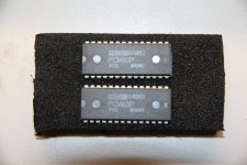
For Sale Burr Brown PCM63P-K DAC D/A Converter IC Pair NOS Genuine Korea

I have 2 PCM63P-K available. They have never been used or soldered in any way except that I did insert them in a DAC but never powered it up as I was going to do some other mods to it and never got around to it. I used to do warranty work for ADCOM, Parasound, and Behringer so I know they are genuine NOS. $120 plus shipping; PayPal only.

Sold "as-is" and no warranty is expressed or implied. No returns or refunds. Sells and ships to USA residents only.

Attachments

  • IMG_4668.JPG
    IMG_4668.JPG
    376.5 KB · Views: 123

Pioneer SA-5500 MK11

Hi


This HiFi amplifier uses two PA3002 power ICs for its L & R output and both have blown. This part is totally obselete. On checking on the net, as a replacement UPC1188H they say,can be used as a substitute. I replace both sides with this part. Now the problem I face is, when I turn on the amp, there is a loud hum but no audio and then if I turn the volume or bass up, the sound comes on but goes off, then comes on again and fades off. This keeps repeating and if I touch the chassis, the hums fades but comes on again. Is this a problem with the replacement IC or a power supply problem. The voltages to pin 3(+vcc) is +21V and pin10(-vcc) is -21V which is correct.


Thanks

KRK Rokit 5 2nd gen low bass

Hello,
I have a KRK rokit 5 2nd gen , recaped with low ESR nichicon, replaced a few 104 caps and resistors with correct values.
The speaker works but the bass is very low and the high from the twitter is really high .
did the same with the other one and it worked fine , same parts used .
where can I start checking ?
No more black junk, I cleaned it all up and re did all the corded connections with new ones .
Any help would be appreciated.
Thanks

Effects of low voltage to rectifier tube

I'm working on my first direct from schematic build (see below) and have a power supply related question for Asano/LW.

I plan to use a Hashimoto PT-160 power transformer with the following specs:

P.120V​
S.320V-280V-0-280V-320V AC140mA​
0-2.5V-6.3V 3A 2 circuits​
6.3V 2.5A​
5V 3A​
I should note that I plan to use a 5V4G in place of the 83V as a rectifier; however, the current schematic is asking for 380V and my transformer only outputs 320V. I'm curious to know - for this project and moving forward - what effects this lower voltage will have on rectification and if there are any adjustments I need to make down stream in the power supply. Perhaps there is a better rectifier tube choice...

That said, is there anything I need to consider in the PS when adding a second channel for a stereo configuration. Seems pretty straightforward, but figured I'd ask.

Many thanks in advance!
Jonah

Attachments

  • asano_loftin_white.jpg.html.jpeg
    asano_loftin_white.jpg.html.jpeg
    44.1 KB · Views: 358

McGee Radio Speaker Catalog - 1982

In 1982 I was 13 years old and in the hunt for a good pair of speakers. I had 20 watt Pioneer stereo receiver and was salivating over the Boston Acoustics A60s. But at $200 a pair they were well out of my reach.McGee1982_cover_M.jpg

I asked a stereo salesman about building speakers. He told me to write to McGee Radio and request their speaker catalog. I remember the December afternoon when I came home from school and the catalog had arrived.
(PDF of the catalog is here: www.tinyurl.com/mcgee1982)

A few weeks later I mailed ‘em a check for $82, which got me a Peerless TP165F 6.5” woofer and Tonegen T011-020-0 Tweeter, the same unit Boston Acoustics used in their A60. (Both of these drivers are pictured on the front cover.) I built an ugly but quite functional set of speakers that sounded just as good as the Boston A60s.

By the time I was 17, I was selling my speakers to friends and advertising my biz in the newspaper. Then I got a distribution agreement with a dealer in Lincoln Nebraska, Sound Dimensions, who started selling my “Acoustic Design Ltd” brand next to KEF, Denon and B&W.

When I was 23 I moved to Chicago and worked for Jensen for 3 years where I designed OEM speakers for Honda, Mazda, Ford, Chrysler and Acura.

In 2022, speaker design is back to being a hobby; here is one of my recent designs:

https://www.diyaudio.com/community/threads/ultimate-open-baffle-gallery.123512/post-6682515

The McGee catalog was terrible by today’s standards... it told you all kinds of irrelevant information (like the flux density of the magnets) but almost no specs you actually needed to know, like SPL or Qts. I’m not even sure the people who ran the place really knew that much how to design a speaker.

Nevertheless this humble catalog was where I got my start. Huge fodder for my teenage imagination. Even today I still enjoy flipping through this catalog and asking myself the question, “If you were ONLY allowed to source these 1982 components, what could you build then if you knew what you know now and had the tools you have today?”

Did anybody else buy stuff from McGee Radio in Kansas City?

Catalog: www.tinyurl.com/mcgee1982

Tube models & LTspice, trouble with (odd simulation behavior)

Hello, totally new here. I have some experience with LTspice, but not with these tube models (2 of the "Ayumi_LTspice", contained in the zip).

Could someone with experience tell me why this simulates so poorly (takes ages), and the crazy behavior when I actually attach the "HV" output label to the left end of R15 (it's disconnected in the attached schematic) - i.e. instead of the +366V I'm seeing a large negative voltage, as if the tube circuits do some black magick there.

Notes apart from that: the outupt transformer model may be crap, it's after measurements with an ebay LCR meter on a transformer I have laying around, but the L2 winding seems awfully low in series R and inductance - then again I have no other output transformer to compare to. Also, the power source is not as in the orig schematic, it's the supposed output of some cheap power transformer from a tube radio I just "shot" on ebay, arrival pending.

Attachments

Fender Princeton 65 DSP amp intermittent popping - any ideas?

Picked up a little Fender Princeton 65 DSP for gigging, really clean sound (had to replace the driver after my second gig as it has blown though!)

Recently it’s been ‘intermittently popping’. I’ve left it sitting whilst on, not touching a thing or shaking it, and it randomly pops a few times every few minutes or so. 99% certain this happens post the ‘PWR IN’ jack - any ideas what it could be?

Schematic can be found here: https://www.manualslib.com/manual/1183721/Fender-Princeton-65-Dsp.html?page=13#manual

help a newbie with 3 way crossover design

Hello! Im not a big Hi Fi audio person, so sorry if these questions are stupid 🙂

Anyways, I need to design a setup. The setup in question has a Woofer (4.5 ohms where I need it to crossover), a midrange speaker (10 ohms where I need it to cross over), and a tweeter (6.5 ohms where I need it to cross over). One of the speakers (the woofer) has a hump between 300-600 hz, so I need to begin my decent for the crossover before that. For the lower range of the mid, the crossover should be at 600 hz. I would like to use a 2nd order butterworth for all of this with a Q of 0.707.

the higher end is slightly more standard, however, I think i need to use an LPAD filter, because the efficiency of the tweeter is around 6db higher than that of the woofer.

Im starting to design the situation in spice. I have attached what I have so far.
unnamed.png
unnamed-1.png


I started to add the LPADs on the midrange speaker, but not the tweeter yet. The problem is that in the graph, the midrange speaker is slanted on the top and I have no idea why. Ive tried using calculators, but every one gives me a different answer. If anyone can help by explaining what I need to do or giving me equations so I can calculate it, that would be great! sorry this is so specific, it is for someone who is extremely particular in what they want. hopefully this doesn't sound too crazy and is possible to do.

Thanks so much and I look forward to hearing from you soon!

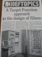
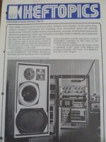
KEF Topics Literature

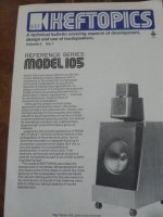
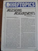
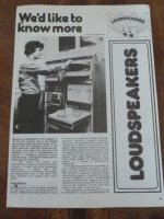
KEF TOPICS LITERATURE (Technical Bulletins)

Great collection of vintage bulletins covering KEF speaker design.

Loudspeakers "We'd like to Know more" by Richard Chapman

Misleading Measurements by Raymond Cooke

How KEF builds its speakers and focus on its cross-over design and components and introduction of its speaker models and KEF Kits (2 separate articles)

"A Atrget Function approach to the design of filters"

Reference Series MODEL 105

$3 each plus USPS First class postage

Attachments

  • P1070413.JPG
    P1070413.JPG
    81.5 KB · Views: 60
  • P1070414.JPG
    P1070414.JPG
    57.1 KB · Views: 64
  • P1070415.JPG
    P1070415.JPG
    55.8 KB · Views: 65
  • P1070416.JPG
    P1070416.JPG
    52.7 KB · Views: 78
  • P1070407.JPG
    P1070407.JPG
    54.5 KB · Views: 64
  • P1070417.JPG
    P1070417.JPG
    69.2 KB · Views: 67
  • P1070418.JPG
    P1070418.JPG
    61.5 KB · Views: 64
Projects by fanatics, for fanatics
Get answers and advice for everyone wanting to learn the art of audio.
Join the Community
507,921
Members
7,893,793
Messages

Filter

Forum Statistics

Threads
406,495
Messages
7,893,793
Members
507,921
Latest member
bedomes