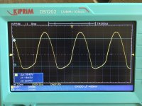
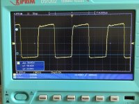
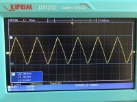
Hi, I got my new oscilloscope up and running. Tested the Vac with an 8ohm dummy load resistor. Made some basic measures and took screen captures (see below).
1. The first image is a sine wave (1Khz) at about 0db (from the AVC) and as you can see, the bottom of the wave is doing something funky.
2. 2nd image is the same input/output levels except a triangle wave form
3. 3rd image is the same input/output levels except a square wave form
My system is a streamer (2V output) --> autoformer volume control --> amp. The sine wave form is clean until about -3db on the autoformer, then the bottom of the wave starts to flatten (as evidenced in the image #1). As the autoformer volume control moves up to a maximum of +5db, the bottom of the sine wave form flattening gets worse. So, I need help interpreting these images. Is the issue with the power amps, AVC or streamer?
Schematic of my amp is attached. This is the 35T SPUD/OTA experiment that I am running. BTW: the sound is wonderful at low and medium loudness. But once the AVC is at -3db thru +5db, the sound gets distorted. This correlates with the scope measurements. I am getting a 14K OPT to replace the 5K OPT, as this should help the bass which appears to be much of the distortion.
Any input would be appreciated.
Attachments
Welcome to the road of knowledge and instrumentation.
The first picture shows a badly distorting overdriven single end amp. Try lover level until both "up" and "down" tops are similar.
The first picture shows a badly distorting overdriven single end amp. Try lover level until both "up" and "down" tops are similar.
You’re hitting a limit and it can’t swing low enough. Reduce the input signal and it will start getting better.
Is the limit within the amplifier or the driving signal from the AVC/Streamer? I believe its the amp, as the voltage increase from the AVC/Streamer is relatively stable. But, the Impedance of the AVC increases as the control knob increases, so not sure if this is the issue. Probably the amp.
This is getting more interesting.
1. Jan - The measurements were taken at the speaker terminals. So, measuring Vac.
2. I then decided to measure Vac signal at the Grid vs. Ground. The same distortion is measured at the Grid vs. Ground. In other words, the distortion is generated from the AVC/Streamer, not the amplifier.
It's also puzzling that only 1 part of the sine wave is distorting. Why would that be?
Thoughts?
Item #2. Not necessarily true, if over driving input stage you will start to draw grid current, at some setting the source impedance of the driving signal may be high enough so that insufficient current is available to satisfy the required grid current and distortion starts to appear at the grid. Turn down the volume until distortion at the input just disappears and have a look at the output, likely it will still be distorted but less so, if that is not the case then the amplifier design needs improvement as the driver clips before the output.
Another possibility is that the streamer is struggling to drive your TVC, disconnect from the amplifier connect a resistor across the output of your TVC equal to the input resistance of your amp and confirm that you now have a clean waveform. If not repeat without the resistor,
Another possibility is that the streamer is struggling to drive your TVC, disconnect from the amplifier connect a resistor across the output of your TVC equal to the input resistance of your amp and confirm that you now have a clean waveform. If not repeat without the resistor,
Last edited:
Jan - no feedback
Updated measurements:
1. Vac measured at the TVC RCA output (with 600ohm resistor to simulate the amp's SUT load) has no distortion. Clean sine wave at max output.
2. With the amp powered OFF: Vac measured at interconnect cable input into the amp's step-up transformer: Clean sine wave at max output.
3. With the amp powered ON: Vac measured at interconnect cable input into the amp's step-up transformer: distortion starts to barely occur with 9 TVC clicks from max (approximately -5db). This is prior to the step-up transformer and any other amp circuitry.
4. Vac measured at speaker cables connected to 6 ohm resistor: distortion starts to barely occur with 9 TVC clicks from max (approximately -5db).
Kevinkr - how do these results relate to your point regarding insufficient current to drive the grid?
You forgot the output of the step up input xformer.
But anyway, if the input to the step up has the same distortion at the same clicks as the amp output, it's not the amp.
Maybe you are just overdriving the amp. How much is the undistorted output from the amp, and is that what you would expect?
Jan
But anyway, if the input to the step up has the same distortion at the same clicks as the amp output, it's not the amp.
Maybe you are just overdriving the amp. How much is the undistorted output from the amp, and is that what you would expect?
Jan
We have already established that with the amp powered OFF (no B+, no Filament voltage): Vac measured at interconnect cable input into the amp's step-up transformer: Clean sine wave at max output. So I tried something different, filament voltage ON (just filaments, not B+), the distortion appears. In other words, at 9 TVC clicks the distortion appears when only the filament voltage is ON (no B+). Without B+ and with filament voltage, why does the distortion appear?
BTW: 9 TVC click measures 10Vpp on the scope = 6Watts @ 8ohms which is well below the capabilities of the tubes at the given operating point. According to the spec sheets and curves, the tube should be able to put out 25Watts with the Ua=950V, 50mA and -6.5V bias.
BTW: 9 TVC click measures 10Vpp on the scope = 6Watts @ 8ohms which is well below the capabilities of the tubes at the given operating point. According to the spec sheets and curves, the tube should be able to put out 25Watts with the Ua=950V, 50mA and -6.5V bias.
With filament on, you get grid current if the signal at the output of the input xformer is too high.
No need for any B+ to get grid current flowing.
Even with the grid slightly negative, you get grid current.
It seems you just overdrive the input with 10V pk pk which is 5V peak with a 4.8V neg bias?
Sure-fire recipy for grid current.
Jan
No need for any B+ to get grid current flowing.
Even with the grid slightly negative, you get grid current.
It seems you just overdrive the input with 10V pk pk which is 5V peak with a 4.8V neg bias?
Sure-fire recipy for grid current.
Jan
Thanks Jan. This makes sense to me. Much appreciated. I am going to increase the bias to -7V and see what happens. More to come!
OK, progress (I think). The table below shows different bias points and the corresponding distortion (Vac input at Grid prior to the input SUT) with filament voltage ON.
The last measurement (12.4Vdc bias) gives a 30Vpp which is only 3 clicks (+2db) from max output. This is 20Vpp increase compared to the original measurements.
| Bias | Vac (Grid vs. ground) |
| 10.9 Vdc | 23.5 Vpp |
| 11.4 Vdc | 26.2 Vpp |
| 12.4 Vdc | 30 Vpp |
The last measurement (12.4Vdc bias) gives a 30Vpp which is only 3 clicks (+2db) from max output. This is 20Vpp increase compared to the original measurements.
So, now you need to figure out what the max output voltage of the amp is, and work backwards to find the gain you need to avoid overdriving the input stage at the bias the input stage needs according to its design.
Whats the max output voltage you want, and what is the amp gain?
Jan
Whats the max output voltage you want, and what is the amp gain?
Jan
- Home
- Amplifiers
- Tubes / Valves
- Noob oscilloscope analysis needed


