Mark Levinson 333 problem

Hello,


I have a broken Mark Levinson 333 that I want to repair for myself. It's working so far, but I have a problem on the Volage Gain board, which is why I can't figure it out at the moment.


The following were defective so far:


Q37,Q39 and the CR55 had passage.


After I replaced the parts, the Q36 gets around 100°C, but in the other functioning channel it only gets around 40°C


I had measured all the transistors so far and didn't find anything unusual. What could that be?

Attachments

Best ring radiator compression driver?

Has anyone tested what's the difference between e.g. a BMS 4540, Eminence n151m and B&C DE360?
Or how about other small CDs that can play up to 20kHz like the Celestion CDX1-1425 and CDX1-1412?
Which can play the lowest, highest and has the least distortion etc?
My goal is to play at least close to 20kHz flat at up to 125dB/1m, so not that much for a CD and it will go in a constant directivity waveguide.
I have 40-90W per channel and fully parametric DSP to correct the output.

Here are some tests I've found, but they don't use the same waveguides so I don't know how comparable the results are:

n151M test

DE360 test

CDX1-1412 test

Musical Fidelity A220 issue with hum on new output mosfets installed.

Hi All

So a friend accidently blew this amp up due to a short in his speaker cabling, Upon inspection it uses BUZ900P and BUZ905P outputs, this amp had been worked on before because the transistors had been changed before and they did not look original.

Finding a schematic for this amp is near impossible, although i managed to find a shcematic for the A2 which is similar.

Anyway i gave the amp a good going over, all new electrolytics, new emmiters (as one had been taken out). I luckily had some spare buz900ps to test the amp.

Now with the original 900P/905P It worked with no issues, i could adjust the idle current/bias to 60mv (across the emmiters) and above i had it playing for hours. My friend decided he wanted all new outputs as the original ones were a mismatch and had been replaced in the past.

I decided based on research to use Exicon ECX10P20R/10N20R outputs. I used a device to measure them and match them best i could.

To make sure they were fine i did one channel at a time, here is my issue. With one channel running 10P20R/10N20R and the other with BUZ900/905 it worked without issues.

As soon as i replaced all the outputs on both channels to exicons i get a low level hum from the speakers and output if i try and adjust the idle current over 40mv?

The only way to stop the hum is to have it running at say 35-40mv, if i got higher i get an annoying hum from the speakers. At first i thought i had damaged something so checking voltages showed nothing bad.

I replaced the outputs back to the buz900/905s and no issues or hum.

So my question is what is going on? i have a few ideas.

1. Could have an issue with the new mosfets? maybe one or two are faulty
2. They are not matched for the amp and not a good replacement choice?
3. Perhaps the gate voltages are different and the driver transistors need to be updated to match the new outputs?

I could leave it at 40mv but then its not running at class A and i really want to get this running as it should. Any advice or tips would be appreciated.

Thanks


IMG20220201114233.jpg


IMG20220201114125.jpg

IMG20220201114244.jpg


IMG20220216154246.jpg


IMG20220218133140.jpg

Attachments

  • IMG20220201114244.jpg
    IMG20220201114244.jpg
    40 KB · Views: 314
  • IMG20220216150718.jpg
    IMG20220216150718.jpg
    56.7 KB · Views: 340
  • IMG20220216154246.jpg
    IMG20220216154246.jpg
    43.6 KB · Views: 286
  • IMG20220218133140.jpg
    IMG20220218133140.jpg
    29.6 KB · Views: 267
  • IMG20220218145407.jpg
    IMG20220218145407.jpg
    94.3 KB · Views: 302
  • IMG20220218161044.jpg
    IMG20220218161044.jpg
    43.6 KB · Views: 280
  • IMG20220218161829.jpg
    IMG20220218161829.jpg
    42.1 KB · Views: 327
  • IMG20220218161836.jpg
    IMG20220218161836.jpg
    52.8 KB · Views: 302
  • IMG20220218161842.jpg
    IMG20220218161842.jpg
    41.2 KB · Views: 253
  • IMG20220218161900.jpg
    IMG20220218161900.jpg
    41.4 KB · Views: 328

Croft Vitale transformer identification

Hi,

I’m hoping someone may be able to correctly identify the pictured transformer.

It’s fitted to a 20 year old Croft Vitale valve preamplifier which is showing short circuit across one of the secondaries and blows the 500ma internal fuse.

The part number shown on the front returns zero in Google search and unfortunately the genius and ever helpful Glenn Croft is no longer with us. The closest in size and value I’m able to find is a vintage RS components 207-144 available on EBay for around £20. Would this be a suitable replacement ?

Any advice gratefully received.

David.

Attachments

  • IMG_1100.jpeg
    IMG_1100.jpeg
    497.7 KB · Views: 171
  • IMG_1101.jpeg
    IMG_1101.jpeg
    605.9 KB · Views: 152
  • IMG_1095.jpeg
    IMG_1095.jpeg
    506.3 KB · Views: 157
  • IMG_1096.jpeg
    IMG_1096.jpeg
    436.6 KB · Views: 162

Variables (Subjective).

I know there is very little for the subjective on this forum but I am experiencing a strange phenomenon. I operate a 2.1 desktop system. Over time I have replaced the satellites with increasingly large bookshelf speakers. The intention was to make the 8" sub optional (I live in an apartment. I have neighbours).

Long story short . . . my latest satellites are 2-way with 6.5" woofers. They sounded awful, boxy and shallow . . . until today. Today they came to life. For the first time ever the neighbours banged on the wall when the sub was off.

I can only consider 2 variables. 1: (Me), but my neighbours have acknowledged the change in bass response. 2: Atmospheric conditions, temperatures are 10 centigrade lower than 3 days ago.

Question about a pin at oscilloscope probe connector

Was buying passive probe for an old LeCroy oscilloscope I acquired.
Going through the manuals I narrowed down 2 probe models that seems to be default setup to the oscilloscope model.
One thing I am confused is regarding a tip right next to the BNC connector on the probe. Is this tip auto-retracting and would just slip into probe when connected to channel input, some sort of ground pin? Or is it pin specific to newer models? Or is it designed to just touch the oscilloscope case when probe attached for maybe reference ground or something, but I think that should be done by the cable shield in the BNC cable?

The pin is highlighted in the picture below.

Tried contacting LeCroy but I have to make an account first, and the account has not been processed by their sales after few days.

Attachments

  • PP005A.JPG
    PP005A.JPG
    67.5 KB · Views: 129

P3A Comparison table ( long .... )

P3A is my favourite amplifier of this class ... i have designed my own pcb ... did a few things on it ... and this become my favourite amplifier and a standard to listen for almost 3 years now together with a diy nearfield monitors 6.5" visaton +vifa ...

I repair give or take around 200 amplifiers per year so i thought since except scopes loads and generators i also want to listen to the amps i repair i normally hook them up to my system and listen from them a few hours

Since i have a few standards created from my setup while listening most of the time my amplifier from the same tuner ( same radio station ) the same cd player and for reference always the same music for more than three years now. In this post i would like to provide some information about the amplifiers i repair may be start some questions about them and listen to others opinions but as a base i will use my listening expirience from the P3...always regarding sound qualities and never power

P3A construction and set up
dual mono 250W trafo per channel 2x28AC
psu caps 2x10.000 mfd on board
MKT input cap 4.7 mfd bypassed with 100nf mika
350 pf silver mica input filter
LTP matched pair +thermal junction
VBE attached in pos driver
82pf styroflex miller cap for VAS
100 PF multileyer cap on the driver
multiturn
120ma biass
BD139-140 family for drivers +VAS ( philps )
outpouts are MJL1302A 3281A motorola originall ( zeck replacement sets )


i normally listen from a passive shunt relay source selector with Alps blue line 47K so most of my tests do not include crosstalk issues since this configuration is almost unbeatable and since i am in the comercial bussines and most of the amplifiers i repair are comercial Japanese amplifiers there is actually no point to try to compaire the one with the other ....

Questions are about sonics, colourations ,ends , how deep , how clear , how crisp, and goes on and on

Most of the amplifiers i repair include tone controls so still comparsion is not that fair but lets thing of defeat switches where ever they exist...

here is a few things i have to say for my amplifier as made that will be followed of a few scope readings and then i will start posting the things i have seen in the amplifiers i repair ...

I will try to post as many details possible about these amplifiers and feel free to email me i f you have any questions or schematic requests

the P3A as is together with the Visaton/ Vifa near filed monitors become a bit endy ...means that this set has absolutelly no problem to deliver low frequencies or high frequencies....Bass is plenty extending often to very low frequency without any problems without anything excecive , punchy and tight but delicate... midle and soundstage are very very present but extremelly balanced and vocals or strings are very pleasent with the slightest sign of distortion and with a lot of depth .... sound stage is so perfect that can provide the placing of the vocals on stage easilly ... now high is one of the most nice since no matter how many remain crystal clean and extremelly detailed at various types of music ...

i t seems that the particular setup will deliver exactly what the producer had in mind ...negatives are that the all system performance has slight U eq performance meaning that midle is a click lower ...but just a clik...

then again it seems that if you play a terrible production the amplifier will make it even worst ...that i cannot explain if right or wrong ...The impression i have is that the amplifier is way too free with no llimmitations of any kind and under this ...sounds logic

thanks for listening ...here we go ...scope readings

Attachments

  • 1 KHZ NO LOAD.JPG
    1 KHZ NO LOAD.JPG
    113.7 KB · Views: 9,125
  • 10 KHZ NO LOAD.JPG
    10 KHZ NO LOAD.JPG
    404.2 KB · Views: 8,769
  • 100 KHZ NO LOAD.JPG
    100 KHZ NO LOAD.JPG
    121.2 KB · Views: 8,276
  • SQUARE 1 KHZ NO LOAD.JPG
    SQUARE 1 KHZ NO LOAD.JPG
    121.5 KB · Views: 8,117
  • SQUARE 10 KHZ NO LOAD.JPG
    SQUARE 10 KHZ NO LOAD.JPG
    124.2 KB · Views: 7,937
  • SQUARE 40 KHZ NO LOAD.JPG
    SQUARE 40 KHZ NO LOAD.JPG
    125 KB · Views: 1,444
  • TOP VIEW.JPG
    TOP VIEW.JPG
    148.9 KB · Views: 3,252
  • 1 KHZ RES LOAD  CLIP.JPG
    1 KHZ RES LOAD CLIP.JPG
    135.6 KB · Views: 3,075
  • 10 KHZ RES LOAD  CLIP.JPG
    10 KHZ RES LOAD CLIP.JPG
    124.8 KB · Views: 1,192
  • SQUARE 1 KHZ RES LOAD CLIP ( FULL OUT ).JPG
    SQUARE 1 KHZ RES LOAD CLIP ( FULL OUT ).JPG
    124.8 KB · Views: 1,381

Audio Note kit 1 SE amplifier

Hi guys, we refurbished an amplifier built by Audio Note kit 1 with 300b end tubes and by measuring the primary/secondary voltage ratio resulted for the 4 ohm output a ratio of 25 and for 8 ohm a ratio of 17.5 both corresponding to a Z=2.5K but THD>5% for 6.5w. Replacing the load resistor with 8 Ohm and 16 Ohm respectively yields Z=5K and THD<3% also at 6.5W. Did Audio Note erroneously show that the outputs are on 4-8 ohm, what do you think?

Attachments

  • 20231109_172408.jpg
    20231109_172408.jpg
    519.2 KB · Views: 272

Doubts battery

I have doubts:

here the temperature varies 33-35C

1) I have AA NI-MH 2600mah batteries from Toshiba, I contacted the manufacturer and he said that there is no problem with the battery life if you store 0% or 100% the reduction in battery life only occurs when recharging

2) the original Toshiba charger does not have a percentage display so I charged all AA Ni-MH 2600mah Toshiba batteries to 100% and I stored them at the temperature I mentioned, I would need to recharge them after how many days or months without harming life battery usage?

3) I have Chinese Nokia BP-5L and original Xiaomi BM20 batteries, I charged them all to 3.8v and stored them at this temperature of 33-35C, after 6 months I saw that their charge dropped a little to 3.78v, which Would it be a longer and safer period of time to charge all of them without compromising their useful life?

Moving Coil Prepre PSU: Basic Questions, What am i missing?

I won't lie, most of the time when i built DIY audio stuff, i'm blindly following ready made schematics. So i did 20 years ago when building my 2sk170 PrePre and the following RIAA stage. Now, over the years i have gathered crates full of electronic components stuff, often MIL spec parts, which i wanted to use some day to rebuild things that actually work, but have some flaws, maybe only optical, sometimes it was just me modifying into a wrong direction because i didn't have parts at hand, no money or whatsoever.

Now the time has come, the amount of parts in my garage is getting annoying. So i decided to "build it away" and get my final stereo setup done.
One of the DIY devices that has a flaw is the PSU of my phono amp. It humms a little bit. It is basically only LM7824/LM7812 with some filtering caps. So i thought to myself i had to go look into the crates what i have.
What i found is a nice little Collins choke with 2,5H/100R at 0,11A. I thought it could be a good idea to use it with a decent 30V toroid, some 4,7mF caps and two LM317 regulators for creating a dual power supply. The needed voltages are +12V@40mA and +24V@60mA.

I turned on PSU designer to simulate that and... wow... i'm getting 30V @ 1,4mV of ripple only? Can that be correct? I mean plus the additional rejection of the LM317s which should be around 60dB for each stage that should make a very quiet phono PSU in the nanoVolts region right?
Now what i would do is adding a LM317 stage to regulate for 24V for the MM stage (approx 60mA) and behind it another LM317 to regulate for 12V for the MC stage (approx 40mA). Maybe add another RC in front of the second LM 317. Should take off some heat from the reg's shoulders and should reduce ripple even more. Maybe something like 20R with 4,7mF or so.

simple choke PSU_2.JPG


Ok, so i'm not the smartest guy when it comes to designing circuits (and living with women). So i have some basic questions.
Everyone is building shunt regulated PSUs etc. No doubt they work good, but for me they are hard to understand and build. If i interpret PSU designer correctly, i wouldn't need more than these few parts plus etching a little PCB for regulators etc to get away with it? Does that mean all the effort put in shunts, low noise regs, huge filter caps etc is only for cost reasons because of rather expensive chokes? I mean actually you can get a choke with these values around USD 10 to 20 used or so. Can this be true?

Also another basic question: I would like to build a test setup. Do i have to worry inrush current could destroy the choke? Maybe should i add a current limiting resistor?

Thanks for your help!

I am just too lazy!

OMG I have so much crap in boxes. Projects, projects, dreams and failures and more projects..
somehow never the exact part.. hello Mouser. Goodbye $$.
I cannot live long enough to use or learn how to use it all up!!
oh well. better to join up here and learn and see what others actually accomplish 🙂
43 Years as a Tech. About 35 of those years suxed, lol. Should have stayed in the New England area,

73's AE5ZN

Tubelab SPP - Bias of 12AT7 Phase Splitter?

DYI Audio folks

I have built a point-to-point version of Tubelab's SPP amp and had some difficulty understanding how the bias of the phase splitter section of the 12AT7 works. When first built, using the specified value 75K resistor as R106, the grid voltage on pin 2 was a couple of volts higher than the Cathode voltage on pin 3. For example, 72.2v on pin 2 and 70.6v on pin 3, when B+ is around 280v. I changed R106 to 150K ohms, which nicely turned this difference around. This approach was a suggestion by rknize on the SPP thread in the Vendor's forum. FWIW, I'm using new reissue Mullard 12AT7s

Is there a simple explanation for how this splitter is biased that anyone can offer, or refer me to, that would explain how the tube is biased and why changing the 75K resistor to 150K worked, and whether that's the best resolution of my bias issue? Thanks in advance for any assistance on this.

Simon

Tubelab SPP.jpg

Preamp/Power Amp Mashup - Possible?

Hi everyone,

I will start this off by saying I found this forum via a bit of googling but everything y'all are talking about is well above my pay grade. It's like reading a foreign language. That said, this seems like the place to ask, so I figure I'll do so - I am basically trying to see if the modifications/build I am thinking of is even possible - not "affordable," "optimal," or even "sensible," but possible.

I have a 1970s Peavey bass amp. I love the tone I get from Channel A to death. I don't necessarily care about Channel B or the combined two channels. There is a pedal manufacturer who makes a pedal replicating Channel A, and I may buy one at some point in the future. However, these amps are currently a dime a dozen, I think I paid a hundred dollars for mine and less functional ones that have been stripped for parts are even cheaper.

Being a 1970s Peavey, it has a number of drawbacks - it's 2 feet long by 1 foot high by 8 inches deep, it weighs about forty pounds, and even at that size it's 130W RMS. It has 1/4" jacks rather than Speakon outputs, and it has no balanced/XLR output to run to a board or front of house.

Now, the sensible thing to do here is to get a small class D amp that has these features and run it through the effects loop, and indeed I have done this with some success in the past. But I don't like carrying around multiple amps and having to hook things up. I want it to be in one package, and having something totally different than everyone else appeals to me.

So - is it possible to build a single, elegant solution, combining the preamp from Channel A with a lighter, louder, class D power amp (ICEPower or the like)? Can this be done for a price that does not rival that of a used car? Is this just insanely stupid and not at all worth pursuing? Assuming the answer to the last question is "no," who, if anyone does this kind of work? I mean, in theory I could, but given that I don't even know how to read a schematic I'm not sure it's a project I'd like to tackle.

Cheers!

Unregulated rectifier boards connected together

Aim; I want to have more capacitance

Some info

1. Only board1 has a rectifier bridge. This means AC is only going Too this board.
2. board2 (± V and ground pins on the missing rectifier) is connected to the corresponding locations in board1 immediately after the bridged rectifier
3. The boards are on top on each other using hex spacers.
4. This is what the input looks like.

Screenshot_20231111_160808_AliExpress.jpg


Would it work? I thought of having rectifiers on both boards and then they share the transformer secondaries but I read that's bad idea.

Thanks for the help.

is this a dead transformer on a Technics 1200?

Acquired a Technics 1200 MK2 that won't turn on. I took the platter and plastic cover off to take a look. Right away noticed there was what I assume to be magic juice residue in the well that that the power transformer sits in. No external evidence of liquid spill or anything of the like.

I plugged in to see if I could do some basic testing as far as I might understand. I measured where the power cable leads plug in and got 120V AC, then again the two red wires that run into the transformer case. Again got 120V AC. Then measured the two yellow wires that plug into the mainboard, got 0V AC. Would this indicate a dead transformer?

Just want to be somewhat sure before I go ahead with an order for a replacement transformer assembly, which comes with power cord, power input board, and transformer..

PXL_20231007_202250061.jpg

PXL_20231007_202236100.jpg

Crossover Conundrum - CX2310 vs. CX3400

Okay, I am about to buy my first ever rack crossover and am torn between two Behringer models, the CX2310 V2 or the CX3400 V2

https://www.behringer.com/product.html?modelCode=P0CCS
https://www.thomann.de/gb/behringer_cx2310_v2.htm

https://www.behringer.com/product.html?modelCode=P0CCT
https://www.thomann.de/ie/behringer_cx3400_super_x_pro_v2.htm

I plan to split it in 2 only, running 2 18" subwoofers and 2 full range 15" + tweeters. Low and high respectively.
I do like the extra features on the 3400 but it does seem a little more complex to set up and "tune" than the 2310.

Which one would you pick.... And why......?


/DATABASS

Adcom 5800 restoration kit – eBay

I was hoping I could get some opinions on this Adcom 5800 restoration kit. Cost is stated at 295.00 (make an offer).

https://www.ebay.com/itm/1656357443...jyrKVaT2T3usOX53luZLTpFOsQ==|tkp:BFBMpJL6v-pi

It does not seem a super far-fetched price for everything that is included, just in my opinion, and of course it would be a timesaver in-regards to having everything in one package instead of researching everything myself, and searching out all of the part numbers, parts, etc.

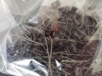
The one thing that I do question is the kit has 22000uF capacitors instead of the 24000uF is that came stock in the unit. I also inquired if the transistors are hand matched, and the seller stated they were not. I had looked up for a replacement 24000uF capacitor, and I could not find any around that appear that they would work and the seller said that is one of the reasons he dropped the capacitor, micro farad range down to the 22.

I have placed the description from the seller of the kit below in case people rather read it here than searching through the eBay ad itself.

Any opinions, thoughts, etc. on if this kit seems to be worthwhile would be greatly appreciated. Thank you very much for your time.

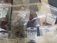
Description from eBay item:
The scarcity of good, honest techs who can do good and reasonably priced restoration/rebuild of audio equipment inspired me to create this restoration kit. In today's day and age, it is difficult to find a knowledgeable technician who can service your audio gear properly. I have seen many poor quality restorations of equipment that cost way too much for their owners. In 99% of the cases, only a few parts were replaced, instead of a full and proper restoration job.

A proper restoration must replace all electrolytic capacitors on all boards. Do not fall for partial kits that restore just one PCB (power supply, power amp, etc.). This is not a good or proper way to restore your audio equipment. It is the same as with car tires; one should never replace just one tire and keep the other worn-out tires on. A proper rebuild requires a full recap of all PCBs.

On the other hand, if one succeeds in finding a good tech, the wait time is usually 6-12 months for the unit to be serviced, and costs are sky-high. I have been servicing audio equipment for many years and have developed deep respect for all good equipment. Knowing how amazing and warm these units can sound, I decided to put together this kit. It includes very good upgrades and improvements that must be done to the unit. This restoration kit will make a huge difference in the sound quality. All the parts are of high-quality Japanese Nichicon / Rubycon / IC / United Chemi capacitors.

I am extremely particular about the quality of the parts provided in this kit. Knowing how many bogus/fake caps, diodes, resistors, etc. are out there, I source all the parts from reputable wholesalers and buy them in bulk.

Vintage audio equipment has the potential to deliver rich and authentic sound when it is properly restored. Not only can it enhance your listening experience, but it can also evoke memories and bring joy to your life. Let's work together to bring your vintage gear back to its full potential, and make sure you have the music you deserve.

Why am I getting very little sound from this EL84 P-P amp?

Greetings friends. I've put together a small power amplifier around a pair of PCBs sold as Dynaco 6V6 Push-Pull Amp:

EL84PPAMPvoltages.png


This is my first Push-Pull build, and a bit of a Shoebox build, as I already had the power transformer. It has a pair of windings for HV and LV, so each channel has its own dedicated power supply:

Login to view embedded media
I got it all hooked up and the voltages looked good, they're written in red in the diagram above. Hooked up a pair of speakers, and got nothing. Well, a tiny, tiny bit of very distorted signal out of the left channel when I open the volume pot all the way. There is a 100k Log pot on the input as a volume control I forgot to draw in there. Is that 10k input resistor too big? Is this thing meant to be fed a much larger input signal from a Preamp or such? I've no experience with the floating paraphrase - is the cathode bypass cap meant to be polarized?

I'm getting no hum or buzz at all, just a tiny bit of signal coming thru. And when I touch the meter probe to pins 1 and 6 on the preamp tubes, I get very clear taps coming thru the speakers. Voltages look right - what am I missing? should I bypass that pot on the frond end and see what I get, then reduce that input resistor to 1k or less?

thanks!

will

For Sale USA-CA: 4 Madisound Open Baffle/Dipole Subwoofer Boxes

4 boxes for open baffle subwoofer. Cut for the Seas L26RO4Y driver (for adding subs to LxMini).

Two painted, two unpainted.

$30 for one, or $100 for all four.

Pickup in Sacramento (or in SF/on the way but that will be in a few weeks

Thanks

S

Attachments

  • 20231109_123228.jpg
    20231109_123228.jpg
    387.8 KB · Views: 70
  • 20231109_123235.jpg
    20231109_123235.jpg
    377.4 KB · Views: 70
  • 20231109_123339.jpg
    20231109_123339.jpg
    480.5 KB · Views: 68
  • 20231109_123344.jpg
    20231109_123344.jpg
    480.6 KB · Views: 71

For Sale miniDSP 4x10 HD in California. $300

Hi

I have a 4x10 HD in good condition with original boxes and power cable, no remote. Available for local pickup in San Francisco, or Sacramento or anywhere in between.

$300 + Shipping.

Thanks

Shri

Attachments

  • 20231020_163922.jpg
    20231020_163922.jpg
    298.2 KB · Views: 94
  • 20231020_163928.jpg
    20231020_163928.jpg
    427.1 KB · Views: 124
  • 20231020_163950.jpg
    20231020_163950.jpg
    338.7 KB · Views: 100
  • 20231020_163956.jpg
    20231020_163956.jpg
    303.6 KB · Views: 97
  • 20231020_163959.jpg
    20231020_163959.jpg
    238.5 KB · Views: 96

Are there any 3rd-party programs to force Bass-redirection and LFE gain globally on my W11 PC?

I used to use a Creative Sound Blaster X3 connected to a set of Logitech z607 5.1 speakers for my PC, which I converted into an all-in-one entertainment system in my lounge room including using it for TV and a home theater, and the bass redirection passed sound 80hz and lower from all 5 satellite speakers to my sub. I went to my onboard Realtek on my B550 MoBo because it has loudness equalization for gaming which my Sound Blaster X3 does not. The problem is its bass management only works for the front left and front right speakers and not for my center, rear left, and rear right. I hooked up my SB X3 again only to find a Windows update that happened in the meantime has broken bass redirection completely. Is there a program free or paid (as long as it's not a monthly or yearly subscription) that would allow me to have bass redirection from all 5 speakers globally with LFE gain included, so I can disable it in my Gigabyte Realtek audio panel and use said program? An example of my conundrum is the DOS game Exhumed, running through the Raze source port, that supports surround sound. When I open a door in front of me I hear the bass as the sound of grinding stone is heard in front of me, but when the door closes behind me the sound is flat and quiet, even when I set the front speakers to -10dB and the rear speakers to +10dB. My sub is set to +5dB.

Seeking a better understanding of the physics behind selecting ideal T/S parameters for a small TH

To start, if you're aware of other threads/links on this subject please feel free to reference.

Backstory: Since joining this forum years ago and learning hornresp, I've played around with hundreds of combinations of subwoofer designs and speakers in hornresp and it has become one of my favorite ways to burn time. It's not uncommon for me to see a driver, lookup the T/S parameters, plug into hornresp and see if I can make a box with the flattest response curve between 40-100hz.

Example: Eminence Legend BP 102 in a ported box vs TH smoothed with a 2mh inductor in series

1697221448641.png


When I swap out the Eminence Legend driver with a JBL GT5-10D, everything goes crazy:

1697221678941.png


There doesn't seem to be much I can do with the TH dimensions in the GT5-10D to flatten it out. Therefore it seems this driver just isn't suitable for a TH unless I'm really doing something wrong here (I do want to know).

If this is not a mistake on my part, I'd really like to understand why this is happening.

I'd also like to hear any opinions on using the Legend BP 102 in a TH. These dimensions seem very reasonable and easy to build, especially if I build a TH with only one turn. I'm not concerned with maximum power (I see it will reach xmax with ~50 watts), just something with good response that is not too big and easy to build.

Settings for the Legend BP 102TH:
1697222089592.png


Bass reflex:
1697222135501.png


Settings for JBL GT5-10D TH:
1697222158910.png


Bass reflex:
1697222187928.png

Mission Model "750 LE" (Limited Edition - 750LE) vs. "750" - which Differences on Drivers and Crossover Network ?

As I know, the main difference consist on the enclosure resp. cabinet version. But maybe there are additional differences on the electrical parts.
Because on the web I have found only information concerning the "LE" version I also think it is possible that this model "750" was only manufactured and thus only available as an "LE" version.
Thank you for clarify.
P.S.: A friend of me want to replace the drivers for bass-Midrange and dome tweeter because the voice coils don't longer work in the right manner.
Which currently available drivers are close to those from genuine used ?
Thank you for an advice.

Here a review from the "LE" version
https://www.tnt-audio.com/casse/miss750e.html

Mystery DIY Speakers

I've had some diy floor standing speakers hanging around for quite a while, something I had to buy to get something else and have now decided to do something about them.

They have 2X Seas P21REX drivers per speakers and an Audax 25DT tweeter installed between them, the crossover I'm sure isn't correct as it just has a coil and capacitor installed, nothing else!

I'm sure some design must have been followed when building them can anyone shine a light on possible crossover designs etc?

Anyone interested in these LM3886 PCBs?

It's been a long time since I posted here and I hope I'm not breaking a rule.
I have some unpopulated boards I made with a friend back in 2008 that I thought maybe some could make use of. I need to actually get a count of how many I have but there's a small quantity. Maybe 10 or 20.

They're setup to biamp a single speaker so there's four LM3886's to drive a woofer and then a single LM3886 to drive a tweeter.
They also have an optional crossover which, I think is a linkwitz-riley style and there's both a 12dB and 24dB. If that's not wanted there's pads for an RCA input jack directly into each amp.

I used a pair of these for many years until I finally gave them to a friend a few years ago. As far as I know, they're still working.
The board only has one modification which is I had to add a capacitor to the single LM3886 circuit, I think in the feedback loop to drop the DC offset as I was using it to directly drive a tweeter. The four LM3886's with the so called "servos" seemed to work beautifully on the two I built.

They were originally intended to be bolted onto the original rear panels of powdered advent speakers, but I also had plans to use them as stand alone amplifiers as well, it just never happened.

Anyone interested?


front.jpg


back.jpg


xovertop.jpg


amp2.jpg


IMG_3428.JPG


capmod.jpg

22R dual emitter resistor help

Hi All,

I’m looking to replace a .22R dual emitter resistor for a dynacord powermate 600 That has gone into protect mode.
1, 5w 0.22ohmn JX2

I’m Having bother finding one.

Is there a substitute I could use please?

I have confirmed 10 faulty components so far on one channel. The other channel is ok.

Thanks in advance

Attachments

  • IMG_6747.jpeg
    IMG_6747.jpeg
    336.7 KB · Views: 117
  • IMG_6748.jpeg
    IMG_6748.jpeg
    278.9 KB · Views: 117

Is the CS43198 a same fake?

Hi! Everybody knows Cirrus Logic DACs CS43131 and CS43198. Once I noticed a discrepancy between the sound of my CS43131 and its measurements. After some research, I came to the conclusion that its brilliant results are fake. I have not any source with CS43198, so it would be interesting if someone checked my findings with it.

Fake 1. 352kHz and 384kHz support
Both chips accept such streams, but few people noticed the fixed setting of digital filters for these modes: 0.263Fs. In other words, frequencies above 92.8/101kHz will not be played at all.
Screenshot_8.png
Screenshot_7.png

Fake 2. Noise I (THD+N)
The noise floor in wideband measurements, which is also rarely used, has a steep rise above 40 kHz.
meizu_sinad384.png
On the FFT, the signal harmonic bases are more wide compared to, for example, es9038q2m.
CS43131_sinad.png
9038d sinad.png
I'm not an expert, just an advanced user. If this is not a consequence of active noise shaping, then at least it looks that way. That is, the real THD+N should be noticeably worse.

Fake 3. Noise II (DR)
According to the standard test, CS43131 shows a DR of at least 130dB(A), similar to good professional chips. It was unclear why I couldn't hear it. The following test was carried out. A 30kHz@0dB signal was mixed into the standard 1kHz@-60dB. 30kHz is far enough from the [20Hz-20000kHz] range so as not to interfere with the measurement too much.
meizu_preamp_aw2.png
Result DR=129.8dB(A)

meizu_1k+(+sin30k).png
The noise floor rose by almost 20dB!
Result DR=110.3dB(A)
This confirms the rumors about variable gain, I suppose.

I very briefly repeated this test on the ES9038Q2M to avoid an error.
d6k_1k.png
Result DR=122.8dB(A)

d6k_1k+(+sin30k).png
Result DR=120.9dB(A)
In general, there is no difference of 20dB here.

Logic of Currus
Of course, I can't know it for sure. I believe the dynamic gain is needed for outstanding DR. The noise shaping helps to improve THD+N measurement. And the huge noise hump is reduced by a non-switchable filter. I don't want to blame the CS developers for anything. I just don't think the CS43131 is a high quality HiFi chip.


PS Many thanks to IVX for exellent equipment!

Silver micas various values lot

Hello.
I have theese dipped silver micas, 300v most are 1 % , there is 3 kilos, I would like to sell them as lot.
I have no idea about how many, but it's on the other side of 1000.
Was thinking 300 euro .
33pf 84.5pf 130pf 160pf 174pf 177pf 270pf 280pf 316pf 330pf 354pf 372pf 378pf 470pf 632pf 1120pf
1240pf 2920pf 1480pf 1500pf 4005pf 4008pf 4300pf 4340pf 4540pf 4860pf 4990pf 5500pf.

Attachments

  • 20231110_095614.jpg
    20231110_095614.jpg
    420.2 KB · Views: 105
  • 20231110_095720.jpg
    20231110_095720.jpg
    414.8 KB · Views: 109
  • 20231110_095726.jpg
    20231110_095726.jpg
    368.7 KB · Views: 100
  • 20231110_095736.jpg
    20231110_095736.jpg
    330.4 KB · Views: 99
  • 20231110_100656.jpg
    20231110_100656.jpg
    278.9 KB · Views: 110

SSE Power Transformer Advice

George's most recent advice is that the power transformer should be 700VCT (350-0-350). Looking at Hammond's potted offerings I see the 373XP rated at 700VCT @ 127mA:
  • 5V/2A - this would tie me to the 5AR4 rectifier tube @1.9mA heater current but that's not a big deal to me.*
  • 6.3V/4A - this should be sufficient: 2xKT88 =3.2A, 1x12AT7 =0.3A, Total 3.5A Other output tubes (EL34, KT66, etc) would need even less heater current.
Does anyone see a problem or caution with this?

Hammond 373XP

* Edit: Some other rectifier tubes run on 2A heater current but that would be right at the transformer max with no margin.

any Class-D modules that can operate from a 63Vdc rail?

I would like to refurbish four subwoofers. Each was previously were outfitted with a class-AB plate amp, which unfortunately is terrible. I powered the plate amps from a 300VA transformer that has dual 45Vac secondaries, which translates to an unloaded DC secondary of about 63V, and I would like to re-use them (there is one in each subwoofer box). I would like to remove the remaining amp guts, re-build the power supply, retain that large heat sink from the old AB amp and mount the new amp module to it. I have lots of 100V can style caps that I can use to make a beefy linear power supply. I'm just looking for an amp module to work at this rail voltage. I would prefer not to add other DC driver voltages if possible, although I would consider that. The drivers will be 4R nominal 12" subwoofers.

I would like to keep the cost at or below $200 per amp module and am looking for at least 250W@4R. Perhaps there is an older ICEpower or UCD module (e.g. UCD400) that would be good when only used for subwoofer duty?

Other suggestions welcome!

Ferro fluid replacement on 1" dome tweeter

Frist time trying replacing ferro fluid on old 1" soft dome tweeter and seek kind advice from experienced members.

When I google, there are several different ul (microliter) such as 100, 300, 650, 900ul. If I replace 1 inch dome tweeter, do I just need 100 microliter per each 1 inch dome tweeter? It looks like 300 ul is the most popular one from the number of units sold somehow.

And, how much filling the ferro fluid? My guess is that it is not to fill all the way up since voice coil needs to be going in then it will overflow.
Do I fill about half way and it is about right?

Thank you very much in advance and any advice would be hugely appreciated.

Connector Identification Needed

Have a 1970's Quad Sanyo Receiver DC6100K with an early type 12 pin connector on the back -

Does anyone know more about the type of connector and what plug would have been used to marry them together.?!

By the way there is no manual (yet) ....still searching for one...must be one out there somewhere!

Thanks in advance

Attachments

  • Sanyo Receiver Connector.jpg
    Sanyo Receiver Connector.jpg
    249.7 KB · Views: 160

James Loudspeaker A2.1 amp trouble

I have a James loudspeaker a2.1 amp with a humming noice on the .1 (Subwoofer) output, sounds very much like wind blowing and it comes and goes but never disapear complitly.
I have no idea what kind of amp it is but my gues is chip class ab or class d amp, it has a Switch mode power supply if it makes any differens.
Any suggestion where to start the localisation of the problem.
The sub channel has a phase 0/180 degree button on the front. When I press that button it gives som scratching noice.
My hope was a cold soldering but after trying to resolder the legs to that bitton it stays the same as before.
James loudspeaker does not answere my e-mail or messenger messages. I have no schematics for the amp.
Where to start?

Speaker sound qualities vs speaker parameters

Hi,
I have built my first speaker about 20 years ago, but I always built a ready plan or used the trial and error methode to build/improve something.
The speakers are quite good what I have now, but I feel, I need to dive deeper if I want to step further. I have started to learn what Thiele/Small parameters are, but don't fully understand yet, how to use them.

For me the following qualities are important in a speaker's sound:
1. Frequency response
2. Dynamics
3. Clean sound
4. Detailed sound stage
5. Good resolution

1: The frequency response is the easiest part since it is possible to correct it by a DSP. Currently I use wideband speakers, thats why I need some DSP correction.
4: The good sound stage comes from good phase response under 2-3kHz, but don't know what is above.
What about the other qualities? Could you please give me some advices, or a good reading/watching material?

Someone mentioned in a thread, that the detailed soundstage and the good resolution is not possible in the same time. What is the reason behind this?

Aleph 3 how is power 4 ohm

In the aleph3's manual is written the peak power on 2 ohm :120 watt.
On stereophile the graphic is that an aleph3 give 32.8 on 8 ohm
55.8 on 4 ohm and 40.. on 2 ohm.
Ok but this is with a sinusoidal signal but what is the power impulsive on 2-4-8 ohm
it's because in the manual is written that the max output is 8 amp and 23 volt.
I can understand (but I know that is not so) the aleph3 give with an impulsive signal
120 watt on 2 ohm
240 watt on 4 ohm

It's impossible I know...
but what is real the power on the aleph3 in this condition?
Someone can help me?

piCorePlayer = piCore Linux + Raspberry Pi + Squeezelite

piCorePlayer = piCore Linux + Raspberry Pi + Squeezelite + LMS

piCorePlayer is a dedicated Squeezebox player (like a Duet receiver) for your Raspberry Pi. It is built on a small read-only linux (Tiny Core/piCore) and Triodes excellent Squeezelite player. It is small, very small, only 75Mb.

December 12 2015

Please try the new release (piCorePlayer 1.22).
Ralphy has been a great support and help during the development - so thank you very much.

https://sites.google.com/site/picoreplayer/home/news

Changes:
  • Updated kernel 4.1.12.
  • Updated piCore (even faster booting).
  • Touchscreen support improved (the official raspberry 7" touchscreen).
  • Calibration file included.
  • Jivelite can be installed from webpage.
  • VU-Meters can be changed from webpage.
  • New high quality default VU-Meter made by forum member Kolossos - thank you very much.
  • Backlight on/off (Jivelite settings/screen/screensavers/when stopped/Display off ) then the backlight will be off when not playing, and on when you touch the screen.
  • Ralphy is providing two versions of squeezelite. The basic version which is shipped with pCP allow playback of pcm, (wav/aiff), flac, mp3, ogg and aac. It is only 1 Mb in size. The ffmpeg version is bigger (12 MB) and allows in addition playback of ALAC and WMA via build in ffmpeg. In the Main page you can choose which version you will use.
After customizing Jivelite you need to save your changes to the next reboot. This is done on the webpage ("advanced tab" in the bottom and choose "backup").

Download

https://sites.google.com/site/picoreplayer/home/download

This software has been around for a couple of years now, but has a fairly low profile at diyAudio.

regards
Steen & Greg
  • Like
Reactions: Bas Horneman

Gauss meters, any reviews?

Anyone know much about gauss meters?
Just wanting to measure strengths of permanent magnets for projects ranging from massive subwoofer builds to robotics? Neo, Ferrite magnets what ever.
Not to expensive maybe under $400 or $500 obviously cheaper the better like it doesn’t have to spot on accuracy but a reasonable one would be good!!

Any recommendations?
Cheers

Sound of various Pass amps

Sound of various Pass designs

Nelson,

It would be interesting to know your thoughts on how the Sony VFET amps sounded vs the Pass SIT amp vs the current (and maybe past) Pass 240 based products, the F series and maybe even the Aleph sound.

Perhaps a short description of each and what that design did really well and perhaps what it could have done better. Also perhaps how it performed into low impedance loads.

I realize how each sounds is subjective and all have sounded good. However, since you're likely one of very few people who have heard each topology, your perspective on each would be great info to know. I also think it could be useful for folks buying Pass equipment (new or used) who are wondering how a particular piece might fit into their system. Finally, it would also help those interested in DIY who may be trying to determine what to build. Essentially, it could serve as a guide that would evolve over time and could even perhaps be a sticky.

I realize you have a long list of to-do's, but given the number of designs over the last five years or so, I think it would be very useful. As this site has grown, it's become very challenging to wade through thousands of posts on each design to try to determine how each compares to others.

Thanks,

Steve
  • Like
Reactions: Freedom666

0.68uf paper oil caps any use in audio?

Also got some 0.1 here all made by rubycon.
If they have no use in audio I will move them on, but I know people go crazy over paper oil caps, but don't want to hoard too much stuff!
They are rated at 1500V, so may be useful in high voltage circuits that use transmitter tubes perhaps?

Attachments

  • 16969795595417605384334287915280.jpg
    16969795595417605384334287915280.jpg
    435.1 KB · Views: 250

AIKIDO Glassware Preamp

To the point. I have a Glassware Aikido preamp that I have decided to sell for $500. Free shipping within lower 48 states. The unit was built with the following:
1) Manley Labs RCA jacks
2) All silver plated copper wiring.
3) Obbligato copper output caps 600V
4) Special connections to allow tube access to be easier for the owner
5) Glassware PS-21 Power supply made for this application
6) Quality Hammond chassis.

Attachments

  • PB010002.JPG
    PB010002.JPG
    128.2 KB · Views: 276
  • PB010004_01.JPG
    PB010004_01.JPG
    733.8 KB · Views: 237
  • PB010008.JPG
    PB010008.JPG
    306 KB · Views: 232
  • PA310004.JPG
    PA310004.JPG
    276 KB · Views: 215
  • PA310005.JPG
    PA310005.JPG
    251.2 KB · Views: 214
  • PA310008.JPG
    PA310008.JPG
    256.2 KB · Views: 240
  • PB010001.JPG
    PB010001.JPG
    414.3 KB · Views: 236
  • PB010002.JPG
    PB010002.JPG
    128.2 KB · Views: 253
  • PA310001.JPG
    PA310001.JPG
    522.9 KB · Views: 267

Sony TA E86B power on issue

Hello. So I am the happy owner of a TA E86&TA N86 set and ever since I got the TA E86 preamp I have some strange issues with it, mainly when I cold start it.

After the 5-6 second delay from when I switch it on, there is a strong 1 minute of really strange noise, more specifically, there is some strong pink noise followed by a strange oscillating sound, just like when you play those 20hz -20khz sine waves, and then a pretty loud pop after which complete silence occurs. Turning it on and off after being on for some time does not replicate the sound. It only does this after it has been turned off for at least an hour or so.

The preamp has seen some servicing, some caps have been changed, but not all. To me, it sounds like a failing old cap that is charging, but looking at the schematics, after the 5-6 second mute sequence from the moment you power it on, there are three small caps on the power supply board that charge and those caps have been replaced.

I would appreciate a fresh input on the matter since it is pretty annoying and I really like this set so I want it fully working. Thank you!!

Attachments

2x IRS2092S bridged

Hi, I built an amp that uses two smps 12v supplies fed into two 12v to 60-90v stepups creating a dual +-60-90v power supply for an irs2092s amplifier

If i wired 2 irs2092s chip amps in parallel to the dual supply instead of one, could I wire the amplifier outputs (bridge?) to get over 500w and how?

At the moment I'm just using one irs2092s amp that succesfully supplies a subwoofer with max 500w

Also I have the option to set the supply voltage from +-60v to +-90v
What's the safest voltage of the irs2092s amp that provides the best performance
Amp
Stepups
Smps

Attachments

  • Snapchat-875310902~3.jpg
    Snapchat-875310902~3.jpg
    57.2 KB · Views: 223

Latency with Allen & Heath ZED i-10FX interface

Hi! I am wondering if I could get some pointers on how to better use A&H ZEDi-10 as an USB interface with a Linux-based DAW for live sound. My current problem is a noticeable albeit small latency between the plucked guitar string and the sound from the monitors. I suppose it should be fixable because if it is noticeable for a beginner like me, it would be unusable for professionals.

I am a beginner, and I have finally gotten around to trying my newly acquired Allen & Heath ZED i-10FX mixer as an interface. It can send 4 independent channels via USB. I installed Ubuntu Studio distribution, with low-latency kernel, and trying with Ardour 6, which comes with it.

The interface work out of the box with this setup but I hear that delay. I know next to nothing about DAWs yet, I was barely able to figure out how to configure the Ardour session to receive and send the sound back. So, perhaps I need to adjust some parameters from defaults.

I use ALSA as sound engine/bus but I also tried JACK with no difference in the delay. Googling suggested that for simple use like mine - playing a single guitar through - there is no advantage of JACK over ALSA, and Ardour itself recommends ALSA.

I tried to calibrate the latency by plugging the monitor out into the guitar in and running the calibration in ardour - it worked, and I got 81 but I am not yet sure what it means, whether these are even milliseconds or frames or something else.

I am also using a pretty powerful i7 quad core 12th generation laptop, so I should not have a bottleneck there.

Any suggestions? Thanks!

TDA7294 high pass filter

Hi! I have Edifier s730 2.1 system based on TDA7294, 150W+75W+75W
I want to change the value of high pass filter for satelits, now is around 150hz, i want it from 80 hz
Can someone help me with changing the value of Capacitors and Rezistors , and what rezistors and capacitors to change,to get 80 hz frequency
Please help me guys, i am planning to change satelits and i want a good mid bass for my system.

Attachments

  • TDaa7294.png
    TDaa7294.png
    123.9 KB · Views: 179

For Sale Khozmo shunt Quad 10K attenuator, Noble stereo 10K, Alps RK40 stereo 100K

I have some pots/attenuator that I currently have no need, so trying to find new homes for them.

All are shipped from Singapore, depending on my work schedule.
For any order more than $100, I’ll do free shipping. You could combine with my other T.I parts sale thread too.

1. Khozmo 48-steps Quad 10K
Perfectly for any balanced solid state preamps or headphone amplifiers. Brand new.
$230 shipped worldwide.

2. Noble 10K stereo
I have 4 of these. All come with pre-soldered boards but still unused. Much, much prefer the Noble to the Alps RK27.
$35/ea plus $12 shipping for whatever quantity.

3. Alps RK40 100K stereo
Another great pot. They no longer made these anymore, still a better choice than the TKD 2511.
This one is used and pre-soldered, fully working.
$50 plus $12 shipping.


CBC9A7A7-A28E-45A0-B4F3-D0063078593E.jpeg
798E34E0-1BF0-47A7-A794-FE7C07589A46.jpeg
82B8866F-6BAF-45E3-AEC4-2CA435121671.jpeg
45C480D4-F595-4ABD-A857-3CB19CC4A2FE.jpeg
53CFB81C-9E91-4A4D-AACF-6B1E7427513A.jpeg
D101BB80-C664-4112-BD31-CA2D02471B11.jpeg
ADC3AA1C-DE68-4588-B8D1-F1ECCC70E4F4.jpeg

Sony CDP-337 Restomod

Heh Restomod... Going to try and document this here for others to follow / ignore as they see fit

Bought a Sony CDP-337 with a wonky mech. I already have a CDP-227 but this is a step up. Electrically similar is correct but doesn't tell the whole story at all...

that wonky mech first of all. Wonky, as in "drawer doesn't open" 🙁 You can YouTube but it was not quite so straightforward as I thought the lithium grease I had was too much for the rails, so don't do that! Grease for cogs thin oil for slides. Couples with new belts, the drawer now slides out of the player as it's supposed too.

There is a lot going on in this mech and it is satisfying to watch without the lid as the disk is lowered onto the spindle during the loading process

Finds and reads even CD-R's without fail

I'll be coming back to this as I progress...

Andy
  • Like
Reactions: xman2005

ADC Sound Shaper Two analog meter adjustment?

I need to adjust the sensitivity of the analog meters on this ADC Sound Shaper Two equalizer. I have the schematic but the service manual I have is for the LED version so the calibration is different. See schematic I marked up: I marked the front panel adjustment (yes they are all the way up).

To me it looks like VR103 and VR104 will adjust the sensitivity of the meters. Am I correct?


meter adjust.jpg

ADC lowrez.jpg

I have a couple of weird Aleph J problems

My Aleph J sounds wonderful for the most part, but I have a couple of problems that I would like to address.
First one: with no input or output connected and the amp powered on everything looks normal meaning all the Leds are lit as they should be. When I power off the amp the PS Leds take about 1 minute to go completely out. However, with the speakers connected and I power off one side immediately goes dim while the other side is normal.
What could this be?

Second problem: if I reverse the input connections, I get no output from either channel, but the other way works perfectly. I have no idea what to look for to solve this issue.

any advice would be greatly appreciated!!

Mixing and matching RMS

Im installing a Kenwood KDC-X705 along with a SKAR RP600.5 amp to replace the Harmon/Kardon factory junk of 27 years old. The RP600.5 fits perfectly lengthwise where the original was located and has the speaker connections that are perfect too. I like it because I intend to use the 5th channel for a KICKER 43C104-N bundle sub box.

I tried Skar 6.5 coaxials in the front doors and those were aweful sounding. Nothing there!
I've now swapped in TX6.5 loud speakers. Wow, what a difference! Those crank for a super budget price. Will they last and for how long?

The front doors can accomodate one 6.5" and one 4.5", each mounted close together and each has a separate wire from the original amp location.
I want to run the Skar TX4, mid/tweeter in the 4.5" location.
The vehicle has 4.5" speakers in the rear above the hatch in the headliner. I wanted to run those too, but substitute 6.5" somehow.
If I forgo the rears, I could use chs 3&4 for the TX4 mid/tweeters and tell the Kenwood Excelon to compensate via its crossover programming.
I want to combine the TX6.5 loudspeakers with the TX4's and possibly use a crossover (do they need it) and connect speakers in the rear, more TX6.5's

I've heard that I don't really need rear speakers but they are nice to have when the rear hatch is open too and more MID for that size speaker is nice.

Should I forget the rears and use the amp's 4 channels on the fronts only, or can I get away with powering the fronts together on 1&2 channels, and the two rears on the chs 3&4? Will a XO be needed on the front or can the AMP be tuned to compensate?

Skar TX6.5 RMS 150W 100-8000 Hz
Skar Tx4 RMS 60W (pair) 60-21,000Hz

I hope I made that clear.

Attached is an example of someone putting a Kicker 46CSC654 in the headliner.
Attached is the door configuration of the 6.5 and 4.5 speakers.
Screen Shot 2023-11-08 at 1.02.12 PM.png

Attachments

  • Screen Shot 2023-11-08 at 12.56.38 PM 1.png
    Screen Shot 2023-11-08 at 12.56.38 PM 1.png
    488.6 KB · Views: 75

2 Counterpoint SA 12s, run one channel in each amp for stereo

I have, in my infinite wisdom (please dont tell my wife), acquired 2 Counterpoint SA-12s. One has a blown mosfet in the left channel, the other has a blown mosfet in the right channel. Is it nuts to think about running the amps as one channel amps. Since the rail fuses and gate resistors are blown or fried, one channel is inoperative. I am assuming each channel produces approximately 40 watts. Should I also remove the 6 DJ8s from the inoperative channel? and the output fuse (s). Tell me why I should not, must not, can not do this?
Projects by fanatics, for fanatics
Get answers and advice for everyone wanting to learn the art of audio.
Join the Community
507,741
Members
7,886,291
Messages

Filter

Forum Statistics

Threads
406,147
Messages
7,886,291
Members
507,741
Latest member
alturas