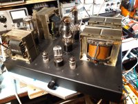
Hi guys, we refurbished an amplifier built by Audio Note kit 1 with 300b end tubes and by measuring the primary/secondary voltage ratio resulted for the 4 ohm output a ratio of 25 and for 8 ohm a ratio of 17.5 both corresponding to a Z=2.5K but THD>5% for 6.5w. Replacing the load resistor with 8 Ohm and 16 Ohm respectively yields Z=5K and THD<3% also at 6.5W. Did Audio Note erroneously show that the outputs are on 4-8 ohm, what do you think?
Attachments
Look at the 300B loadline in AN Kit1 operating point, 2k5 OPT, 8R load.
No free lunch. Limited power (low Ua), high distortion, but bulletproof.
If you use higher Z output transformer (and higher Ua), the distortion will decreasing.
No free lunch. Limited power (low Ua), high distortion, but bulletproof.
If you use higher Z output transformer (and higher Ua), the distortion will decreasing.
It's not so simple.
From the secondary to primary transferred impedance will be almost double, but OPT's primary parameters (inductance, capacitances) remains the same, so it will not really the "double impedance" OPT.
From the secondary to primary transferred impedance will be almost double, but OPT's primary parameters (inductance, capacitances) remains the same, so it will not really the "double impedance" OPT.
Think about a Hi Fi or Stereo as a complete System (recorded music studio and production, signal source (CD, vinyl), preamp, power amp, speakers, room).
No single device by itself can define the total results of the System.
The same goes for parts selection inside of a power amplifier.
Did you mean an 8 Ohm loudspeaker that is 8 Ohms everywhere from 20Hz to 20kHz?
Or,
Did you mean an 8 Ohm loudspeaker that has minimum impedance of 4 to 6 Ohms, and maximum impedance of 20 to 50 Ohms,
when measured across the 20Hz to 20kHz frequency range?
As to decisions of why to use a 2.5k primary, or a 5k primary,
Here are a few tradeoffs:
Primary DCR
Wire size
Number of turns
Maximum DC quiescent current before low frequencies will cause early core saturation.
Leakage inductance
Low frequency response
High frequency response
Required amount of laminations
Primary inductance
Primary distributed capacitance
Size and weight
Desired load impedance (related to the dissipation, etc. of the output tube).
. . . I am sure I forgot a few more factors
Why?
Design of an output transformer is an art, science, and exercise in economics.
Design of an amplifier is also an art, science, and exercise in economics.
Talk to the designers if you want accurate answers.
Engineering designs are a series of tradeoffs, sometimes they are not successful.
Watch the old B&W film about the Original Tacoma Narrows Bridge.
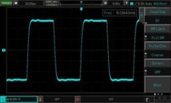
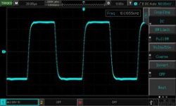
We measured the output transformer, here is the data L=16H R=102 ohm Llk=8mH and frequency band 30Hz-56Khz/-1dB and SQW response at 10 Khz so a very powerful OT Next, all measurements of the amplifier were made on a load resistance of 8 ohm at the 4 ohm output of the amplifier so that the impendance reflected in the primary is5K so the static operating point has also changed

popa marius,
Post # 7 was not in English.
Please tell us about the 2 screen shots:
What are the square wave frequencies?
Is that the result of the 300B driving the transformer?
or, is that a signal generator directly driving the transformer?
If it was a signal generator directly driving the transformer, what was the signal generator's output impedance?
Thanks!
Adăugați marcaj
#7
Sorry, thease are SQW measurment,first picture only the transformer and the next at the out of the amplifier
Last edited:
I hope the images will be clearer, the frequency is 10 Khz and in the case of OT measurement the signal is introduced secondarily with the help of a 10w SS amplifier whose output impendance is very low, so a 0-20 ohm rheostat is introduced adjusted so that the impendance is 8 Ohm. The primary section is closed with a 5K load resistor on which the oscillogram is read
Attachments
- Home
- Amplifiers
- Tubes / Valves
- Audio Note kit 1 SE amplifier


