Simple cigar box shop speakers with TC9FD or FE85?

Hey there guys, I bought a house (!) about a year ago and have a small workshop in the back that I spend a good bit of time doing woodworking projects in. The outbuilding is not insulated, and is basically bare stud walls at this time- I'm slowly adding power outlets, and plan to insulate and put up sheetrock walls over the summer. In the meantime I wanted to throw together a pair of cheap, quick speakers to set on a shelf to run some music while working on projects.

I have a pair each of TC9FD19-08, and Fountek FE85 on hand that I can use, and have some relatively nice little cigar boxes that I was planning to use to make a couple super simple, easy bookshelf types of speakers that wont hurt my feelings if they fall over or get covered in dust. I ran a couple simulations on the speaker DB site simply because it took only a few minutes, and it looks like sealed may not be terrible, even if I am not likely to get any low bass from them- which is perfectly fine for the intended use. Cigar boxes internal dimensions are 5.5 x 4.25 x 7.125" and volume comes out to .0964 cubic feet. Walls are about 5mm. I figure that these will not be super strong, but I can add some braces and they will never need to play very loud.

20220111_205328.jpg 20220111_205351.jpg


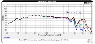
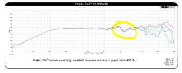
Here's a quick Speaker DB sim for each in a sealed box they look like some stuffing and back wall lining may be enough to make these servicable. The TC9FD looks to have a better response off the bat, but I almost want to use the FE85 for this project just to use them up, and maybe since the round frame may look a little less janky from a front mount perspective, just for the sake of easy assembly. Also thinking of saving the TC9's for a set of Nola Brio clones in hardwood 🙂

Screenshot_20220111-205154_Chrome.jpg Screenshot_20220111-205108_Chrome.jpg


Anybody have any input here? I think sealed is a nice simple way to go, and I'm not equipped to do any simulations on my own. I'm not opposed to a vented box with a simple port cut in, or a section of PVC pipe for an internal port. Maybe add a baffle inside and make a bootleg uFonken out of them?

Transplant?

I've acquired an old pair speakers that I really like the sound of. They offer a refreshing clarity. However, the cabinets are as ugly as sin. I do not possess the skills to manufacture my own aesthetically pleasing cabinets.

I can probably buy a pair of cheap, used speakers for £10/£15 on Ebay. If I buy speakers with a similar (12l) cabinet volume and simply swap the drivers and crossover, am I likely to maintain the original quality?

6V6 solid state power supply

hi guys.
I wanted to ask you a question.
I want to make this amp,
https://diyaudioprojects.com/Schematics/DIY-Push-Pull-PP-6V6-Tube-Amplifier/
but I want to rectify with a solid state, and I have 2 JJ capacitors, one of 32-32uf 500v and another of 50-50uf also 500v, but I don't know what resistance values to put on them, has anyone already made a source like this? or I can repeat the values of the schematic for 6z34 that nothing happens.
As you will realize I lack technical knowledge to do mathematics


Thank you very much for the tip
  • Like
Reactions: Bigun

BIG BOX Audio Research Prototype boards/parts

BIG BOX Audio Research Prototype boards/parts!!!

ARC history right here! Big box full of Proto boards that went on to become famous products! WZJ never threw ANYTHING away. he would make the engineers take all the parts off the prototypes and save them...well years worth of these boards built up and one day we cleaned and i acquired a large load of stuff. I have hung on to this stuff now for nearly 10 years and its time to let it go. I have no idea what all is in here. don't ask. but it is CHOCK full of awesome goodness. tubes, fets, caps, digital boards and who knows what. but for???? $500???? you can have years worth of fun figuring it all out. its a BIG big big box and the price includes shipping in the USA which. will be an estimated $75-100 just for shipping. Open to offers. No trades. Open to discussion/haggling.

Attachments

  • 20230729_122813.jpg
    20230729_122813.jpg
    534 KB · Views: 331
  • 20230729_122816.jpg
    20230729_122816.jpg
    646.1 KB · Views: 309
  • 20230729_122819.jpg
    20230729_122819.jpg
    440.5 KB · Views: 307
  • 20230729_122820.jpg
    20230729_122820.jpg
    388.3 KB · Views: 281
  • 20230729_122828.jpg
    20230729_122828.jpg
    417 KB · Views: 300
  • 20230729_122833.jpg
    20230729_122833.jpg
    672.1 KB · Views: 310
  • 20230729_122839.jpg
    20230729_122839.jpg
    694 KB · Views: 308

For Sale SissySIT R.3 Package

Just Too Many Projects!

I can't see letting this SissySIT R.3 bundle sit in my drawer unbuilt, so its up for grabs!

What's Included:
  • SissySIT R.3 boards
  • Parts to populate amp boards
  • Pair of Edcor PC600/15K transformers
  • Pair of matched TOKIN THF-51S SIT's with curve tracing data by Watanabe

SOLD! including shipping within USA only (via PayPal)

Attachments

  • IMG_0719.jpeg
    IMG_0719.jpeg
    602.8 KB · Views: 238

Bookshelf / Desk Speakers

Hi, I want to build myself a pair of bookshelf / desk speakers/ ( I built in the past a few, I have a woodwork shop, I've done woodworking .
I know the basics of electronics, built a few amps, design myself with the help of this community. anyway, when it comes to speaker crossovers I'm pretty noob, so I'm here for some help.)

I already have picked a pair of Dayton's TCP115-4 and ps95-8.
I'm thinking to put them in separate boxes, something like Focal did, Separate the tweeter ( fullrange in this case but with low pass ) from the woofer.

Firstly I wanted to do a 3-way , same speakers but adding a tweeter crossed at 4-5khz and use the ps95's as mid range , from 400, 800 ? to 4-5khz,.
The woofer TCP115 starts to " cone breakup ? " at around 2.5 -2.7 khz, ( yes I could go 2way with a tweeter crossed low at 1.7 or so but they are big , same size as woofer and pricey)
The full range ps95 has a weird dip at around 2.4khz.

Now what would be the thing to do with that dip at 2.4khz, bring the woofer up to compensate? or bring up that 2.4khz on the fullrange within the crossover?.
I tried some variations in XSim with the data files provided by Dayton.

Before I make up my mind to go 2way with the woofer and fullrange or 3 way with also a tweeter ( maybe the nd16fa-6, since it will be crossed high ) , I want to figure out the crossovers.
Some ideas, help , would be wonderfull.
For the 3way I was thinking woofer - tweeter - midrange, like Focal did, I also wonder that front baffle "curve" concave, what does it do, it's angle I think matters, from a first tought if u imagine a straight line fron each drive they merge into a point. but beyond that point they split up again? imagine laser beams, idk if its the same with the sound. I would go for that just for looks mainly, if it won't hurt the sound . Cabinets will be rectangular with rounded edges, instead of " semi-circle laterals" .
The cabinets, I will make them in WinISD.

For now I'm waiting for the TCP115's and ps95's to be shipped, tweeters for the "3 way ideea " not yet bought.
For crossovers while testing, I have a bunch of components and also will buy proper capacitors, as for inductors I have the posibility to measure their inductance and make them my own.

I have also attached the data files and pdf's .


Cheers, Bruno.

Attachments

DIY subwoofer

I recently started wanting a subwoofer for my setup (computer and retro/entertainment area) and thought building my own would be a decent idea.

I have a basic understanding of what I should do. (Get Driver, build enclosure, and get class d amp) I would just like help for what calculators to use and how big/how powerful of a sub I would need for a 8'x24' room.

The wettest non-audio build thread

This project has stemmed from my fitness SUP project. I have two vehicles under development now. Being amphibious and while on land, there are Australian rules and vehicle standards to comply with. These will slot under the rules and regulations governing E-bikes. It's a different story and set of rules in the water. Both devices will slot under recreational devices and not require registration if they remain under the 2.9kw power for marine use. The limit for land use 250w. Both vehicles will feature dual power trains

FB is mainly a dry ride vehicle with the rider out of the water at all times. The basis for this is a SUP wearing a gokart type frame suitable for the marine environment. This is getting the cross trainer device that I came up with as well as a 250w motor in the PAS format for a pedelec and a secondary marine drive system attached to the x-trainer

NC is a wet ride with the rider sitting around hip level at rest. I am facing the challenge of applying foils to the FB to balance the wet and dry drive systems to only have the fins on the wheels dipping into the water while underway. The foil challenge for the NC is to acquire enough lift to bring the rider out of the water underway

I'll have some pictures coming up later today with the beginnings of the construction. I have still to sort out the axles for the FB

FZT753 FZT653 ZTX753 and ZTX653 in TO126 Outline ?

I am looking for an equivalent in a SOT32/TO126 outline of the ZETEX complementary transistors FZT753/FZT653 (SOT223) resp. ZTX753/ZTX653 (TO92 E-Line) for mounting on a heat sink.
A Vce of 45VDC is enough.
The application is a MC pre-pre which work with +/-15VDC (Linn Linto, LK-1 Kairn).
I will change the genuine condition of the MC pre-pre section in the LK-1 because PCB is burned in this area.
Additional mounting brackets for the TO126 transistors on the LK-1 enclosure - go to
Montagewinkel, 90deg mit 3 Lochern A4 | OBO
should eliminate the issue of overheating PCB.

Maybe BD135/136 or BD139/140 is a good choice ?
Thank you for an advice.

WIMA caps

Hi, Anyone know what type of wima caps are these? ( 5% on the back ) Can I use them in audio , active crossover? . What about these generic yellow ones?
Also i found these unbranded , they are old .
Thank you.

Attachments

  • 20230813_111215.jpg
    20230813_111215.jpg
    387.4 KB · Views: 115
  • 20230813_111223.jpg
    20230813_111223.jpg
    341.6 KB · Views: 110
  • 20230813_111231.jpg
    20230813_111231.jpg
    454 KB · Views: 114
  • 20230813_111251.jpg
    20230813_111251.jpg
    373 KB · Views: 115
  • 20230813_111826.jpg
    20230813_111826.jpg
    375.5 KB · Views: 108
  • 20230813_111715.jpg
    20230813_111715.jpg
    330.1 KB · Views: 107
  • 20230813_111711.jpg
    20230813_111711.jpg
    399.1 KB · Views: 122
  • 20230813_110802.jpg
    20230813_110802.jpg
    422.9 KB · Views: 108
  • 20230813_111826.jpg
    20230813_111826.jpg
    375.5 KB · Views: 101
  • 20230813_112848.jpg
    20230813_112848.jpg
    155.5 KB · Views: 105
  • 20230813_112905.jpg
    20230813_112905.jpg
    147.6 KB · Views: 117

Unusual (at least for me! lol) single-ended GM-70 amp

Greeting fellow members,

This is my first post, my principal interest is (for now) is comparing GM-70 amp schematic, the "contemplative state" before considering building, anyways, what do you guys think of this circuit regarding these aspects :

1 - input impedance?
2 - the use of a output transformer as an input (yes you can warn me about not to go this way, ahah)
3 - is the simplicity of the circuit worth exploring?
4 - the possibility of using a higher plate voltage
5 - the cost (of course I would look for cheaper trans than Tango)

1692022079099.png


Here is the link to the original page : http://www.ononet.jp/~micky/gm70s.html

Here are the published characteristics


1692022475421.png


Happy building and listening!


Olivier

Bit rate indicator for I2S

Hello,
Is there anybody who has an Arduino based bit rate indicator for the I2S signal?
I have a 7-segment sample rate indicator with an Arduino Nano and would like some indication of the bit rate as well.

Does anyone have a schematic and code for such a bit rate indicator?
Just 3 LEDs would be fine. One for 16 bit, one for 24 bit and one for 32 bit.


hjhjazz

I'm a bit confused after reading a few ESL handbooks :)

Hi everyone,

Doin the required study before making a pair of wire stator ESL's for myself, reading up on ESL tech, how to's etc... im a bit confused about "segmentation".

I see people used electrical ladder segmentation (using the excel tool) which i understand BUT the panels themselves are divided in segments too,
to prevent ignoring the rule 1:50 /100 for the width of unsupported foil.
Wont this be mechanical segmentation? and how does it effect the electrical one?
Also in the tool the number of wires used in a "segment" is a bit "grey" it doesnt change values of the ladder resistors?

As you can read/see, i need help and clarification 🙂

Thanks all,
Jerolee

Understanding voltage drop

Hi, likely a very stupid question but since it is around high voltages, I need to understand it.

I am to build a variation of the preamp part of the Dumble ODS. Basically, from this as a source: https://thesubjectmatter.com/dumblearchive/Dumble #0094/094_schematic_12_132.pdf. Just the part with two 12ax7s (without PAB relay and without effects send-return).

So, I need just B+4 and B+5. Could someone explain me what causes the voltage drop between B+1/B+2/B+3/B+4/B+5? And the further voltage drop on the valve? I have found this variation with the voltage readouts: Login to view embedded media . What causes the drop from 400V to 300V between B+3 and B+4 (there is a resistor in between, but it doesn't seem like a voltage divider to me)? And further on, what causes the drop to 200V on the actual valve?

Basically, my idea was to use a supply like https://www.aliexpress.com/item/1005005909458258.html that provides 6.3VDC for filament and 300VDC for B+, and I plan to just cut out the part after 22k resistor after B+3 and connect this power supply there. But I'd like to understand what happens with the voltages before switching the power on...

Thanks.

LM386 circuit design questions

Hi,

I've been trawling posts and forums to debug some noise, squeals, and oscillations on some LM386 circuits I built.

I've synthesised all of this knowledge and calculated a load of component values. I wanted to run this past some people more knowledgable than myself and see if I'm approaching things correctly. I've not breadboarded this yet as I don't have all the components and was looking for some feedback before I order.

Also, please note that I am a complete amateur here. I’m more than capable of plugging numbers into calculations but I don’t fully understand all of the concepts behind these. I’d never heard of Xc for example.

Here's the datasheet for anyone who needs it - https://www.ti.com/lit/ds/symlink/lm386.pdf

Here's a schematic:
LM386.png


So, first of all, C1, the input DC blocking capacitor. The 10K volume pot in parallel with the IC's 50K input impedance results in 8.3K input resistance.

I'm aiming for Xc lower than 8.3K/10 at 100hz (this is low enough for my application, 20hz seems excessive for me). A 2.2µF cap gives Xc of 0.72KΩ at 100Hz so this seems good to me. This is higher than any other LM386 amplifier design I’ve seen online though (ranging from 47nF to 1µF)?

Next, C2. I went by the datasheet which shows 50µF as the best frequency response (Fig 2. Power Supply Rejection vs Frequency). The graph is for 6V supply though and I’m using 9V so I’m unsure what impact that might have. Again, 50µF is higher than the e.g. 0.1µF I’ve seen elsewhere.

For C3, I’m connecting to a miniature 8Ω speaker (well actually vibration speaker element so a speaker coil driver without the cone). The chip’s output resistance is 0.1Ω so I have a total output resistance of 8.1Ω. To work out the capacitor I’m aiming for Xc less than 8.1Ω/10 at 100Hz. A 2,200µF cap gives me 0.72Ω at 100Hz. This is much higher than used in many other circuit. Size and cost seems a more likely factor behind this and I have seen 2,200µF recommended elsewhere.

C4 and R1 form part of the Zobel network. Rather than take the standard values seen in many circuits (generally 10R and 47nF) I calculated these. My speaker has a voce coil/DC resistance of 7.4Ω. recommended resistor value is this times 1.25 and so 9.25Ω. 10Ω resistor is fine. For the cap the calculation is Le (voice coil inductance) / R (9.25Ω above) * R (well R squared but I can’t do superscript 2). Le for my speaker driver is 0.06mH. I dived this by 1000 to get Henries (and multiplied the result of the calculation by 1000000 to get µF) resulting in 0.61µF. I understand that going higher should be fine so a 1µF cap is an easy value.

C5 and C6 are power supply filtering/decoupling. I couldn’t find a source to calculate this so went with a range of advice and settled on 100µF and 0.1µF.

I’m leaving pins 1 and 8 open as 20 gain should be enough for me.

I’m using the inverting input (pin 2) as it’s suggested that it sounds better.

As my calculations result in some higher value capacitors than I’ve generally seen I’ve plumped for some polarised elctrolytics where I don’t usually see them (C1 and C2) so I’m unsure about polarity here.

Phew, so that’s the schematic. I’ve also laid out a board design based upon all of this and taking into account best practice I’ve seen. There’s especially an issue with keeping in, out, and power grounding separated and so I’ve done my best here. I’m using non-standard symbols (heavily drawn from Peter Blasser’s paper circuits) but the one’s which should be hardest to figure out are the circles with black triangles next to them. These are for the input and output jack grounds.

Screenshot%202021-01-29%20at%2008.42.22.png


I appreciate that there’ll be a range of factors such as space and cost and so I’m just aiming for something more ‘ideal’ than practical at this stage.

So, anyone who actually understands all of this properly able to comment?

Thanks for your time.

Help with room

I downsized in the last few years to a 12.5’ x 13’ room in our basement. It has a suspended ceiling with the thin plastic decorative tiles in it. Unfortunately this has to be my music and audio room combined and I’m at a loss as to what to do with it. Essentially every square foot of floor space up against the walls is taken up by something so I’m thinking I may have to go near field. No room treatments and I’m thinking about ditching my mostly budget stuff to start over (except my old Polk Monitor 5B’s which are currently getting a complete xover redo with upgraded tweeters - nostalgia). Here’s a close approximation of what I have going on.

Attachments

  • music room.png
    music room.png
    62.8 KB · Views: 149

Amplification strategy for efficient-ish fullrange speakers?

Hey everyone!

Having just started building a new set of speakers, SBAcoustics SB20FRPC30-8 fullranges in a TL/MLTL type cabinet, I now have to find a good amplifier to pair it with. Given that the speakers will be somewhat on the efficient side (92db), I was wondering about what I should aim to feed them with. I've been using active speakers for years so I don't own an amp at the moment. I have access to one of those tiny, awful Nobsound bluetooth amp and that's it.

Since I'll be listening to them at nearfield levels most of the time, only ever cranking them up to reasonable levels once in a while, I figured I should look for something in the 5 to 30W ballpark. I was tempted to just get an off the shelf Loxjia A30 or SMSL A50, but I don't want to be underwhelmed by my new speakers by not pairing them with the correct device.

I've been browsing on here left and right looking for clues but I'm still at a loss.

1) Is it a good idea to pair efficient speakers with something more powerful, say, 100W? Does it mean getting a better, cleaner response and more dynamics?
2) I was interested in the two amps mentionned above because they both have bluetooth, but then, I read in a few places that using bluetooth will sacrifice extensions in both end of the spectrum, is that true?
3) If I were to go with a DIY amp, how easy would it be to work out a competent bluetooth system for it? (I have a USB dongle DAC, but I'd rather go full wireless unless it means too much sacrifices)
4) Is it even worth my while to be looking at building a DIY amp for under 200euros all inclusive? Or will I get similar results minus the hassle by just getting the Loxjie?

I most of all care about resolution and clean bass extension. My entire design choices with the build I'm starting right now are aimed toward that goal.

Thanks in advance for your answers!

Help with small DC offset on output

Fixed! See last post

I've just got hold of a lovely Integra DRX-7 AVR (9.2-channel, class D) for almost nothing, as it was stuck in protect mode. After disassembly (not a trivial task with this beast!) I found one channel had blown its mosfets (IRF6775MPBF, DirectFET Isometric smd package), driver IC (IRS20957STRPBF), burned a couple of resistors and had a suspect input op-amp (TLC071), presumably caused by a speaker short or similar.

I've replaced the faulty components and everything else on this channel measures OK on my DMM as compared with the schematic and a working channel. Because electronic components are very hard and costly to source in New Zealand, so the parts have had to come from Aliexpress.

It now powers up with sound on all channels (yay!), but the faulty channel has a faint audible hiss with a DC offset of around 230mV - not enough to trigger protection but enough to cause annoying pops when changing settings. The poweramp board isn't accessible without complete disassembly, so can't actually test anything on the board while its running.

I've attached the schematic for the power amp section. Can anyone suggest where to start looking for the issue or what/how to test? Maybe Leaky diode or transistor? Or even fake parts?

TIA, Jon

Attachments

Sony PS-333 Turntable - Seeking to Repair

This Sony ES-333 turntable has not been working for some time. I am looking to get back into vinyl again (thread) so that is why I am considering repairing it or getting it repaired.


Today at 1:35 AM Add bookmark #54

This is what I have, or have access to. The Sony PS-333. Everything in that system is called 333. Maybe a repair thread will help.

Just to recap: it was turning fine with the orange light lighting and all that, then it stopped working. No rotation when tone arm was moved. I gave it to an electronics place to repair they could not. Something about replacing the ICs. I wonder now if it was a simple broken contact or maybe even resetting the tone arm. Wish I had it here.

1685595145252.png

Understanding this "Dynaco 6V6 Push-Pull Amp" circuit + cathode bias in the same

Greetings friends. I got a pair of PCBs off eBay that claim to be a "Dynaco 6V6 P-P" circuit and I'm trying to understand how it works, and hopefully build an amp around it. Here's the schematic offered by the vendor:

Login to view embedded media

So a pair of EL84 in P-P, cathode biased, driven by a 12AX7 in a common cathode config, perhaps known as a Floating Paraphrase.

How can I determine the output of this circuit? The PCB has "10W" printed on it...can I get away with a 10w OPT, or should I go beefier? According to Dynaco literature, we're looking at 13.5v at the cathodes, 370 on the plates and a shared 130ohm cathode resistor.

I'd like to build this amp with an ANTEK AS-1T250 PT. It features 4 secondaries total, 2 for HV and 2 for heater power, so I plan to wire each channel with its own windings. Here's a rough schematic:

Login to view embedded media
I'd like to keep the costs down on this one, so the cheaper 10w OPT from EDCOR is more appealing than the 25w model. Obviously the cheapest config would use a single power supply shared between both channels but I can splurge on two, if there would be any noticable improvement. Still cheaper than a Hammond PT and a tube rectifier.

Thanks for taking a look!

Sony STR-6045 - Styrol capacitors

Hi All,

I continue my learning journey into electronic and vintage amplifier. With the help of @Moolie, I brought back to life a Sony STR-6045.

It was all working well including AM/FM except for this little stereo lamp indicator that would not light up.

I traced the problem back to a few transistors when I decided to measure the capacitors in this area while I was at it. There was one capacitor I could not test (the service manual called it “Styrol”). I said to myself, let’s desolder it without investigating further what it was. Stupid me! 😡 I discovered that these Polystyrene caps have very fragile leads and managed to break one.

Sony_STR-6045-Styrol_cap.png


It seems that it can now be replaced nowadays by Polypropylene caps or Ceramic (NPO COG) depending on its usage.

I see a few threads on DIYAudio.com but they are now getting old, so I thought I would ask. My question to you all, is what is it used for exactly and what would you recommend as a replacement?

This styrol capacitor (C320) is on the input of the transformer (T301) on the schematic.

Sony_STR-6045_MPX-encoder_voltages(2).png


Some more details from the manual for those of you interested:

Stereo-mono automatic switching circuit Q304, D303, D304, D305, D306:

This prevents noisy stereo reception by automatically switching the MPX decoder’s operation into the monaural mode.

Noise signals above 19 kHz are extracted from the emitter circuit of Q301 and applied to the base of 0304 through a high-pass filter (L302, C306).

The coupling capacitor C307 filters out audio components so that the input signal is primarily high-frequency noise.

This noise signal is amplified by Q304 to drive voltage doubler D304 and D306. D305 provides positive fixed bias for Q304 through D306 and D304.

When a weak stereo signal or interstation noise is received the output of D304 is fed back to the base of Q304, and drives Q304 into conduction.

This in turn shorts the frequency doubler output to ground through R315, preventing amplification of the incoming signal, and therefore operation of the 38 kHz amplifier and stereo indicator circuit, Q302 and Q303.

When a stereo signal is received, the signal-to-noise ratio increases, reducing the noise signal It the base of Q304. Therefore Q304 turns off and enables the stereo demodulator circuit to operate.


38 kHz amplifier Q302:

The 38 kHz pulses produced by D301 and D302 are amplified by Q3302. The tank circuit at the collector of Q302 is tuned to 38 kHz to restore these pulses to a sinusoidal waveform. This signal is transformer coupled to the bridge type demodulator to supply sampling drive for the demodulator.

STEREO lamp circuit Q303:

The STEREO indicator lights when the FUNCTION switch is set to the FM AUTO STEREO position and an fm stereo signal is received. The emitter of Q302 is connected to the base of Q303 which is normally cut off.

The circuit operates as follows:

When a composite stereo signal is applied to the multiplex decoder, the 38 kHz pulses produced at output of the frequency doubler yield a higher average current flow through Q302. This forces Q303 into conduction, lighting STEREO indicator lamp PL901.

Thank you all in advance for your help and precious advice.

Krell KSA-300S will not turn on

I'm trying to fix a Krell KSA-300S amp. I hope I don't have to ship it back to the manufacturer because it's so heavy. Hopefully some members here can help me troubleshoot it. I do know how to solder.

Sequence of events leading to the current problem:
1) when powering up, it has about 1 minutes of delay before the output relays clicks on.
2) recently, I can hear a "sizzle" sound (like doing B-B-Q, frying beef) when I turn on the power switch. After 1 minute, the relay clicks on and the amp is fully operational.
3) more recently, I hear louder "sizzle" sound when powering up but the amp is still fully operational.
4) most recently, after the above events, the amp will shut down. I'm assuming the protection circuits kicks in to shut down the amp. No speaker damage. This happen one time after the amp has been on for 1/2 hour. The other time, amp shut down after 2 hours. For both times, after waiting for 5 minutes, I was able to turn on the amp again. The weather here is about 90 degrees lately and I listen at regular volume level. The hot weather probably has nothing to do with this but I thought I mention it.
5) last week, when powering up, I think I hear a "crackle" sound in addition to the "sizzle" sound. Amp did power up as usual but after about 1 hour, the amp shut down. After waiting for 5 minutes, this time the amp will NOT turn on anymore.

Questions:
- I understand that capacitors went out very often and I suspect that it's the same situation here. Anybody knows which one(s)? I have not been able to find a schematics on this forum or at the Krell web site. I also suspect that the problem is on the "start up" board and I suspect (& hope) that the amp section are fine. I have done a internal visual inspection. Nothing looks burnt or leaking.
- I have done a search on this forum but I did not find anything related to KSA-300S. Lots of info on KSA-100S though but the problems are unrelated.

Any suggestions? I plan to "dive" in and do some troubleshooting soon.
  • Like
Reactions: tonykara

A monitor for an e-drum kit

My son has been learning drums for about 6 months and so has been rewarded with a drum kit. Thankfully it has headphone output so the neighbours are spared.

Does anyone have any experience with measuring or designing drum monitors.

Based on my limited knowledge of drums, the frequency response should be from 50Hz to 1Kh; with harmonics extending to about 6-10KHz, although cymbals can extend to some 15KHz.

So I plan to try my hand on a 2 way with a 12 midbass and a dome tweeter in a waveguide or compression driver in a horn/waveguide. It’s an excuse to use all those parts on the shelf.

What is the design targets for a drum monitor?

100dB/1m?
105?
110?

2 way?
Coaxial?

Of course for a few hundred dollars there’s the Alexis Strikeamp 12 and Roland PM-200. The specs are geared towards musicians so little is indicated about the performance characteristics. But they have a mixer and equaliser knobs for tone and knowing Roland, probably has FIR DSP, is highly optimised and fit for purpose. And cost optimised for musicians.

Technics cd player output - bypass these (resistors to ground) nor not

My Technics SL-P477a, already happy with it, but since upgrading the rca jacks, i was curious if i could bypass the resistors to ground. I left the compartor opamp in LM833, but changed the other to LME49860. I had old film capacitors sitting around from speakers i once had, so they had some hours on them and used them. I kept the same capacitance on the caps. I was shocked to hear that Elna is no longer manufacturing the SilmicII

Thank you
Sam


P1490182.JPG


bypass or not possible the resistors to ground? if not i can leave it, sounds great as it is. The mechanism cdm4/19 is easy to come by, as i have spares.
P1490188.JPG


P477a.jpg

Thor & ASP1000 -> :-/

My summer house had a brush with a lightning strike some 15 meters from the house. Main incoming fuses was pulverised. One can see how the kA moved on the garden surface (pic). Unfortunately my system was left on and one of my mono power amps was found with the following symptoms:

  • klicking noise every 2 seconds
  • 1,4 V DC on output
  • blue capacitor close to output blown (pic)

Anyone with repair knowledge of this specific product have any idea?


PS: Also a Didden Silentswitcher was put out of service 🙁

Attachments

  • DSC_1286.JPG
    DSC_1286.JPG
    346.3 KB · Views: 103
  • DSC_1291.JPG
    DSC_1291.JPG
    218 KB · Views: 100
  • DSC_1289.JPG
    DSC_1289.JPG
    289.1 KB · Views: 100

DD M4 blown output section

Hi guys on the bench today i have a DD M4
Came in with a blown output section

All fets are blown. I've since removed all output fets. Amp now powers up with no protect. HOWEVER... I'm not getting any drive on the gates (still no fets fitted) (24N40F)

Had a look at driver card and DD have shaved the part numbers off the drivers.

Does anyone know what output drivers these amps use? Also. Are there buffers used in these amps? All part numbers on the driver card have been shaved

Thanks 🙂🙂
20230815_065059.jpg

Need Help Finding Alternatives for BD140-10 and BD139 Transistors

Hi DIYAudio community,

I'm currently working on a DIY audio amplifier project, and I've run into a bit of a roadblock. The transistors I planned to use, specifically the BD140 (PNP) and BD139 (NPN), are unfortunately out of stock and unavailable from my usual suppliers.

I'm reaching out to the knowledgeable members of this community to ask for assistance in finding suitable alternative transistors that can perform the same function as drivers in my circuit. The BD140-10 and BD139 are critical components for the project, and I want to make sure I choose replacements that will work seamlessly.

If anyone has experience with this situation or has worked with alternative transistors in similar applications, I would greatly appreciate your recommendations and insights

Question re B&C DCX464

Greetings all,

the B&C website lists the DCX464 as a 1.4 inch/36 mm, cf. https://www.bcspeakers.com/en/products/coaxials-hf/1-4/8/DCX464-8. However, either way I measure it, mine appears to be 1.5 inch or 38 mm. The pictures are just for demonstration, I actually measured it with calipers).

Do I have some rejects, or is it sloppiness in manufacturing/marketing?

Kindest regards,

M

Attachments

  • 20230814_100656.jpg
    20230814_100656.jpg
    629 KB · Views: 98
  • 20230814_100618.jpg
    20230814_100618.jpg
    493.7 KB · Views: 80

Another Balanced Microphone Pre-amplifier

I want to design low noise balanced dynamic microphone pre-amplifier, but cheap enough with easily to find component in my country.
I use 2SB737 transistor which have very low rBB, but I'm not sure how much collector current to get lowest noise for 150 Ohm output impedance dynamic microphone.
In this simulation, the collector current is 2.7mA and voltage input noise is 1.7179312nV/Hz½ at 1Khz max. gain.
Simulation used ZTX951 because it have slightly lower rBB than 2SB737. I do not have 2SB737 model.
I use NE5532 op-amp because it is cheap. Dual op-amp is easily to find than single op-amp. In input stage NE5532 parallel, so I can used 560 Ohm feedback resistor.

Gain can be adjust from around 7 dB to 60 dB. Is it enough?
And one op-amp use for clip indicator than use for nothing.

Any suggestion are welcome.

Attachments

Help with shipping

I'm wondering if someone might be able to help with shipping a small mono amplifier from the States (Pennsylvania) to Japan? The gentleman I'm buying it from is getting on a bit and unable to take care of the packing for overseas shipping on his own.

Please send me a PM if you might be able to help with this. All costs covered, obviously. I can also return the favor with the purchase and shipping of any audio items from Japan.
  • Like
Reactions: matsurus

Plate Z ruminations

Hello,

A couple of years ago I bought a pair of big mains toroids from a surplus shop with the intention to try them as PP output transformers. The feature that caught my attention was a 37-0-37V low current secondary winding that I intended to use for CFB, cathode feedback. Together with 2*115V primaries and a high current 19V secondary that would make a 2k:8R OPT with ~25% CFB taps. Practical tests revealed that the transformers worked fairly well although they, as expected, had to be downrated quite a bit for fullrange use.
More about the transformers and my prototype in this thread: https://www.diyaudio.com/community/...ers-as-opts-with-a-little-twist.374308/page-2

As I can remember those transformer did sound quite good and it would be fun to build something with them one day. Sweep tubes would be the obvious choice, either one pair of PL519 (40KG6) or a quad of PL84 (15CW5) per channel as I have plenty of those.
On the other hand I'm getting old (44...) and bored and it would be more fun to build something a bit more... eccentric. I love the look of old 807s and I have a box full of them, including some decently matched quads.
The STC "807 bible" mentions that a pair of triode wired 807s can deliver 15W into 3k p-p at 400V, as seen in the first screenshot. The second picture shows my interpretation of this OP in the vtadiy.com loadline calculator. The third pic shows a 2k p-p loadline at 280V, here the simulator indicates 3,6W in class A1 and 26W in AB2.

AB2 and 25% CFB would require a very serious driver stage, but nothing that can't be done with direct coupled Mosfet followers (PowerDrive) and a much higher voltage rail for the voltage amplification stage preceeding the mosfets. Is this whole idea completely crazy or could it possibly work, perhaps even sound decent?

STC15W.jpg807-3kAB1.jpg8072kAB2.jpg

TPA3116 2.1 Channel BT - Sound cutting every 1s @ low input (video)

Hi,


saw few thread about sound cutting but it was @ high volume.


It was working fine for few weeks, and out of no where, under normal use, the sound is now cutting under low/med signal.


- Mine is at low volume (low signal input), the sound is cutting. see video.
- the 3 channels are cutting in same time.

- If I stop music over BT or Line-in, the speaker are clicking in the same way.


It act just like a overtemp protection, the TPA shutoff and then ON every 1s.


Please, note that the ''shutoff'' click, is way different than the original hiss sound from no signal (battery saver).


Solutions so far :

-I tried many power supplies,
-many speakers (4 to 8 ohms).
- I cleaned the original thermal paste that was on the TPAs legs, put new artic silver.
- Play with volume knobs


Nothing worked.


Final note : if I'm blasting the sound, everything is ok. But its hard for the ears 😀


YouTube


s-l1600.jpg

Flyback diode for relay coil?

Need help with this circuit:
I put together a board to convert a constant 12VDC trigger into a pulse signal to turn on and off an old Classe amp with a RJ12 connection and the circuit worked as promised.

However, I'm wondering if it's necessary to have a flyback diode across the SPST relay coil to protect the electrolytic capacitor and the SPDT contacts.

If the answer is yes, what type of diode should be used? Is it okay to mount two diodes facing each other on the relay coil?

Screenshot 2023-07-31 at 18-03-26 Scheme-it Free Online Schematic and Diagramming Tool DigiKey.png

Amp Layout - mounting Toroids

Greetings, friends, I'd like to build a Power amp with a toroidal PT, the Antek AS-1T250. Amp is based on the Dynaco ST35 with circuits on a pair of PCBs, SS CRC power supply, Edcor CXPP25-MS-8K and everything bolted to an Aluminum top plate:

Login to view embedded media
Toroidal PT will be mounted to the underside of the plate:

Login to view embedded media
Will I have hum with the output transformers mounted in such proximity to the power transformer? Is this baby gonna fly?

thanks for taking a look

will

Two more book recommendations about the history of music recording and the record business, etc.

Installments 4 and 5 of my Tracking Angle series called "A Bookshelf for Lovers of Recordings" are now up.

4 The B Side copy.jpg


#4 is: The B Side: The Death of Tin Pan Alley and the Rebirth of the Great American Song

by Ben Yagoda

Ben Yagoda tries to figure out why the period from the climax of the Great American Songbook era (circa 1945) to the advent of Rock and Roll (1955) was such a Musical Hazardous-Waste Dump (my words not his). The prime example being the fact that “[How Much Is That] Doggie in the Window” spent eight weeks at the top of the Billboard pop chart.

somethingtintheair.jpg


#5 is: Something in the Air: Radio, Rock, and the Revolution That Shaped a Generation

by Marc Fisher

This is a history of pop music from the standpoint of the radio business.

For a while, it looked like broadcast television would put many radio stations out of business, especially because much early network programming consisted of "variety" shows that featured live music. Quoting myself:

"What saved radio was the rise of rock music (indeed, the relationship between local, independent AM radio and rock music was symbiotic); the advent of the Top 40 format; the rise of the Disk Jockey as a star personality; and the opening of the airwaves to previously marginated African-American and Country (Hillbilly) music."

Another very well-researched and enjoyable read.

john

Pure Evoke/Avanti Flow - New Display Module

After needing a new display for my Pure Evoke Flow I found this thread Pure Evoke Flow Internet Radio (please visit the thread to find out about the display and fitting instructions)

I ordered more than I needed from China so that I could get a good price (I hate paying full price for anything!) and so that others could benefit too. They were quickly sold so I got a bit of discount from the supplier and ordered some more.

Now I intend to continue importing the displays as long as there is demand so have created this post in the Group Buy section. Be aware that I am not a vendor or trader, I don't have a shop or any other spares, I am just a private individual helping out 🙂

The new batch are now in the UK and should be with me 12/12/2017 and I will start posting them out as soon as people pay for them.

So - Rather than sending lots of PMs the prices and payment details are:-

1 x display inc 1st class post to UK £18.90
2 x displays inc 1st class recorded post to UK £38.00

1 x display inc tracked post to most of Europe £25.50
2 x displays inc tracked post to most of Europe £43.50

If you are anywhere else please ask.

Payment by PayPal GIFT (to avoid their fee, otherwise price goes up) to :-

ajsprotect-ebay (at) yahoo.co.uk

You must include your full postal address AND your diyaudio username when making payment.

Note - there are 30 displays in this batch with 21 reserved for the following list, the remaining 9 will go on 1st come 1st served basis. If they go quickly I'll start a new list and order another batch.

The list of interested parties so far is:-

elecroly +2
ec1ct +2
Justin76 +1
noigardo +1
Badger +2
Gttnewbie +2
purejon +1
Rowbo +1
Titanium rider +2
Mrg481 +1
Jamie35 +1
Impulse Tryer +2
xtof41 +1
rowers+1
Artimuscrackfrog +1

Recommendations for amp?

Hey DIYers,

I'm in the process of building several things at once, a pair of Heissmann Acoustics' Cinetor Evos, and a few differents fullrange projects, mainly centered around high efficiency, large drivers (Fane 12-250TCs, SBAcoustics SB20FRCP30s).

I was going to buy a Loxjie A30 as an amp, but I figured I might get better results going DIY, for the same price of slightly higher. I have enough experience in electronics to put an amp together.

Between chip amps, class Ds, class A, AB, etc, I'm a little lost here. I gave a look at Pass Labs project but I can't tell anything apart.

Therefore, I'm looking for a recommendation for a DIY amp to build, preferably below 300€, that would help make those higher efficiency (90/92dB) really shine, especially in the bass department.

Full disclosure: I listen at low, medium low volume, nearfield type situation, in a small room, 1/2meters away from the speakers max. I'm looking to squeeze as much dynamic range from the speakers, if that helps...

Any help would be greatly appreciated!

Revox C279 subtle crackling.

Hello fellow audiophiles, I got hands on a revox c279 in quite good aesthetic condition at a very good price... Unfortunately it has a low level, random crackling sound in the left master channel. It comes and goes but it's audible. The first green led in the Vu meter lights up when this happens..It's not very invasive but it makes me feeling uneasy about my purchase.
If fixable, I'm not planning to return it...

Is this something I can fix by cleaning or probably some condenser needs changing?

If that was the case... How can I locate it?

Being an old desk and all, is it worth going the full recapping way? (Self made out profesional)

What would you do?

Thank you!

Please assist reverse engineering this module

My electronic crossover, a/d/s/ 642ix, utilizes switchable modules for changing the crossover frequency. The modules require to change capacitors and resistors.

I’m going to use it with three-way speakers. So, I need to modify the modules.

Attached is the instruction for modifying the modules.

I found my existing module has different component values to the instruction manual. They are as follows:

C1, C4 = 332G (I guess it’s about 3.3nF)
C2, C3 = 562G (I guess it’s about 5.6nF)
R = 20k Ohms
1M = 3M Ohms

I need help to reverse engineer this module. Which frequency it was designed? And what formula to modify it to the desired frequency?

Attachments

  • E9F227D8-1B2E-4D3E-AED7-34EEB17FB640.jpeg
    E9F227D8-1B2E-4D3E-AED7-34EEB17FB640.jpeg
    142.7 KB · Views: 139

MPSA18 VS BC239C

Hello to all.
I intend to assemble a NAP200 clone based on the ZeroZone PCB. But I got a doubt. Given that I have no problem getting BC239Cs but there is a technical reason why the Chinese in the NAP200 clones use the MPSA18s as TR1 and TR2 transistors instead of the BC239Cs or the choice is forced by the discontinued production of the BC239C. Furthermore, how should the MPSA18s be chosen? I saw that in the case of BC239C TR1 must be chosen with an HFE of 500 and TR2 of 430. In the case of MPSA18 what difference of HFE should I consider?
Ultimately I leave the MPSA18 or do I put the BC239C? For convenience I insert the scheme made by someone of good will on this site:

Attachments

  • NAP200_Kit Schematic wt Parts ID & Voltages (2).jpg
    NAP200_Kit Schematic wt Parts ID & Voltages (2).jpg
    774.3 KB · Views: 1,053

Additional MKP/MKS Bypass on already present Cathode Bypass Electrolytic Capacitor for better Sound ?

Both in power and line/phono-RIAA pre amplifier stages are often to find capacitors between cathode and GND.
Unfortunately the various threads under
https://www.diyaudio.com/community/threads/choosing-cathode-bypass-capacitor.255366/
https://www.diyaudio.com/community/threads/cathode-bypass-capacitor.233663/
https://www.diyaudio.com/community/threads/cathode-bypass-cap-vs-no-bypass-cap.254781/
https://www.diyaudio.com/community/threads/help-understanding-cathode-bypass-capacitor.396622/
http://www.nutshellhifi.com/library/FindingCG.html
discuss the cathode bypass capacitor as a whole part, while I am interested in which type of film capacitor is best suited for parallel connection to the present electrolytic cap when space is limited.
In commercial tube amp components sometimes are to find MKT/MKS, MKP or nothing on this point - and this is the reason to start this thread.
Thank you very much for some hints so as related URL's.

P.S.: concerning the RIAA amp device in post #31 - go to
https://www.diyaudio.com/community/threads/schematic-wanted-for-vtl-preamp-maximal.158725/page-2
rises up the question, whether one decide on an MKS/MKT version with a higher value or with the same size for a lower value - but then with the higher-quality - i.e. MKP/FKP version (due the low voltage condition on that point a 63VDC version is enough).

AD1865 DAC goodies for sale

2 complete DAC´s without an analog output stage, with a total of 4 pcs. high-end AD1865 chips in sockets. One board works fine, and one needs the fix shown in the left corner of one of the boards. An IT chip has been dismounted.

4 pcs. Andrea Ciuffoli designet PCB´s made for a single AD1865 chip DAC and a CS 8414CS true hole chip.

4 pcs. CS8414CS SMD chips that will not directly fit into the Ciuffoli PCBs – maybe it is possible to buy a SMD to true hole converter board somewhere.

Price for the whole lot: Euro 200, and transport in a country in the EU + Euro 30

ScanSpeak Bookshelf 3-way

Glad to welcome everyone to this forum. I regret that my first post is asking for advice.
A few months ago I decided to put together a three-way speaker, I chose the right size and design for my taste and room. I ordered the speakers, started to make arrangements for cutting the cabinets for the subsequent assembly of the cabinets. Then, when I started to make the crossover, I noticed that the website did not specify the values of the electric parts. Without going into details, I cannot order a kit from Denmark, no matter how much I would like to. But okay, the crossover can be calculated by myself with a measuring microphone and theoretical articles from the internet (or buy a universal pre-fabricated filter).
But suddenly I found out that the 22W/8534G00 driver requires a much larger volume... Should I recalculate the cabinets for a larger volume (and how to do it), or should I do it as is?
This is a link to the project I'm talking about
Again I apologize for the newbie questions, I will hope for your goodness!

Tascam 52DB Reel to Reel Head section issues?

Hi All,

I would like to know if anyone knows the following. I have a Tascam 52 DB Reel to Reel Machine. The head section are exhibiting issues due to its age and use but I am trying to make the most of its current state.

Some of the rollers (ie. tension, pinch) are worn on one side, but luckily I am able to reposition it as it is held into position with a screw.

These lifters are different, I can't seem to figure out how to turn it so that I can use the good side.
52DBLifterIssues-1.jpg


These lifters lift the tape off the heads when fast forwarding and rewinding but because their worn, their practically sanding down the tapes causing all types of gunk to be on the heads and rollers.
52DBLifterIssues-2.jpg


I was thinking, maybe there is some sort of hack where I can just put a sleeve over it, but concerned the thickness might lift the tape off the heads during regular use.

Another option was to use fine sandpaper and try to smoothen it out, do you think this will work or just cause a massive mess of metal debris everywhere?

Is there a hack way of fixing this, without having to take it for service?

If not, is there a cheaper option as parts will not be easy to find. Can this lifter be re-machined whilst still being on the unit or does it need to be removed?

Based on the service manual, it looks like a 1 piece attached to something - 80, 81, 83?
52DBLifterIssues-3.jpg


If I do decide to remove the lifter myself (the head section looks like it could be removed as a single module and the lifter separately underneath it) and take it to a machining shop like a bearing or industrial repair store, would this be possible and would I likely need to calibrate the unit when re-assembling it, or simply screw everything back in place and it should be fine? I mean the heads look like a one piece unit.

Anyone ever had this issue before?

Any help appreciated!

Thanks.

Ready to start up new amp and need some help to be sure everything is OK photos and schematics

Hi,

I need some help to wire the cliff jacks for the foot switch and the input jack. I have checked all the component values. I don't have the three position switch but it should arrive Friday.

The foot switch jack is wired but I don't know if it is correct. Is my hand drawned schematic correct for the input jack?

Just yell if you need more info.

Thanks

Billy

Attachments

  • IMG_0312 (1).jpg
    IMG_0312 (1).jpg
    73.4 KB · Views: 92
  • IMG_0313.jpg
    IMG_0313.jpg
    77.3 KB · Views: 94
  • IMG_0314.jpg
    IMG_0314.jpg
    69.1 KB · Views: 94
  • IMG_0315.jpg
    IMG_0315.jpg
    50.2 KB · Views: 113
  • Supro_EL841024_1.jpg
    Supro_EL841024_1.jpg
    123.4 KB · Views: 114
  • IMG_0317.jpg
    IMG_0317.jpg
    32.9 KB · Views: 116
  • Supro_EL841024_2.jpg
    Supro_EL841024_2.jpg
    141.8 KB · Views: 88

I need some help solving Issues with my new Supro S-6424 build

Hi,
I started the amp up and recorded the voltages and changes are indicated on the attached schematic.
The channel connected to V1 pin 2 works normally and sounds good.
The channel connected to V1 pin 7 is producing very little gain. ( resolved tone control has to be turned up)
The tremolo circuit is not working. I used a 500K pot with a turn-on switch, and I am not sure if it is connected correctly ( the on-off part).

Also, can someone explain the 100-volt difference in the V1 plate voltages (pin 6 at 145vdc and pin 1
255vdc)?

The handwritten numbers are mine. The printed numbers are Steve Luckey's numbers using a different PT.
I have a series of high-rez photos of the amp if needed.

I have done several hours of troubleshooting without success.

O716bd5.jpg


3xWWlsl.jpg


Thanks,

Billy

a basic discrete buffer

Hi everyone,


This is a basic 9V battery-powered buffer I have been playing with on the breadboard, as I am trying to learn more about discrete circuit design. I know something about electronics but not a lot, and this is the first project where I am thinking about things like thermal and electrical stability. The schematic and LTSpice model are attached. The output stage is biased at about 5.5 mA in order to give 26 mV across R9. Two channels then draw 14-15 mA so may be suitable for some portable applications. I have attached measurements (made using REW and a Scarlett Solo) of distortion for a 1V RMS 1 kHz signal into 33 and 150 Ohm resistors, which both happen to show THD of 0.0013%. At 20 kHz that rises to about 0.02% (using 192 kHz sample rate). Likewise the SMPTE IMD measurement for 1V RMS into 33 Ohms seems reasonable.

For some context, it will be used to buffer cross-feed circuits and will drive my Grado SR-80e and AKG K553 Pro headphones, both of which are 32 Ohm and 114-115 dB / 1V RMS. I listen at about 70-75 dB so 100 mV is plenty of voltage drive for me right now, but in order to be useful (at least for me) for many 'typical' headphones the goal is good performance up to 1V RMS. I realize that this buffer is more limited than almost all of the other projects here, but perhaps it might be interesting to others who only need 1 Volt or so.

While it seems to work well, the primary uncertainty for me is electrical stability. The compensation capacitor was chosen via LTSpice and according to predictions should give at least 50 degrees of phase margin and 9 dB of gain margin for 16-300 Ohm resistors in parallel with 3 nF. I have done a number of measurements (square wave, frequency response, spectrum during operation, checking current draw and whether components get warm during normal operation, etc) and it seems fine driving actual headphones, but my digital scope only goes to 10 MHz and my signal generator is limited to 100 kHz, so I don't feel like I can definitively claim much about electrical stability. It definitely is thermally stable, though.

Anyway, since I am not an expert I suspect that I made some rookie choices / mistakes, and would welcome any suggestions for improvement. I'd rather try changing things prior to soldering it up than after!

Thanks,

Jason

Attachments

  • classABbuffer_v1.png
    classABbuffer_v1.png
    86.8 KB · Views: 596
  • classABbuffer_v1.asc
    classABbuffer_v1.asc
    6.1 KB · Views: 115
  • set0_asio_THD_1kHz_1Vrms_33Ohms_7p7Vbatt.png
    set0_asio_THD_1kHz_1Vrms_33Ohms_7p7Vbatt.png
    126.3 KB · Views: 584
  • set0_asio_THD_1kHz_1Vrms_150Ohms_7p7Vbatt.png
    set0_asio_THD_1kHz_1Vrms_150Ohms_7p7Vbatt.png
    126.1 KB · Views: 392
  • set0_asio_SMPTE_60Hz_7kHz_1Vrms_33Ohms_7p7Vbatt.png
    set0_asio_SMPTE_60Hz_7kHz_1Vrms_33Ohms_7p7Vbatt.png
    116.6 KB · Views: 555
  • Like
Reactions: geraldfryjr

Sacred geometry snake oil?

wtf is this? I guess if you divide nunbers like the reciprocal of the sqr root of 3 squared (.333333) into 345.6 m/sec you can come up with a bunch of ‘ pi’ like numbers (radians for degrees on a circle , or sine wave, or these other geometrically significant triangle coincidences.. just like 22/7 or 11/7, 5.5/7 , 2.5/7 etc are ‘close’ .

Attachments

  • 80002EBF-97A0-4D2B-A755-6775A0B3B5EB.jpeg
    80002EBF-97A0-4D2B-A755-6775A0B3B5EB.jpeg
    60 KB · Views: 141
  • B0959F0D-7E9A-4BEF-B1B7-15ED1971E40F.png
    B0959F0D-7E9A-4BEF-B1B7-15ED1971E40F.png
    59.2 KB · Views: 144
  • D47B2F54-64B7-43BA-A289-D65A53B3EE3F.png
    D47B2F54-64B7-43BA-A289-D65A53B3EE3F.png
    131.6 KB · Views: 132
  • 660DE2E6-EF82-4B64-A864-6C68CC1C5392.png
    660DE2E6-EF82-4B64-A864-6C68CC1C5392.png
    151.7 KB · Views: 145

Possible to use 4 Ohm drivers with 8 Ohm tweeter for a center speaker?

Hello all, I am definitely new to the DIY audio and I was hoping to make use of these two Dayton RS100-4 4” drivers that are 4 Ohm with a Dayton AMY mini-8 air tweeter rated at 8 Ohm. I haven’t gotten to the size of the cabinet yet but I was just making sure my components would be compatible together as a center speaker first.


Also if anyone has recommendations for a good 3 way crossover for this set up that would be great. Thank you for any help here.

For Sale LME49990 (4 opamps) old stock never mounted w/ SOIC to DIP adapters

I bought 4 of these old stock LME49990 opamps from the seller on DIYAudio. I planned to solder them onto SOIC-DIP adapters for my CNC Phono stage but got out of vinyl hobby altogether. I paid $80 for them and $10 for adapters. I will accept $75 for them shipped in cont. USA with Friends and Family PayPal payment.

I have perfect Audiogon and eBay rating so feel free to ask me for the feedback links.

Attachments

  • IMG_6049.jpeg
    IMG_6049.jpeg
    684.7 KB · Views: 81
  • IMG_6050.jpeg
    IMG_6050.jpeg
    709.4 KB · Views: 76
  • IMG_6052.jpeg
    IMG_6052.jpeg
    762.9 KB · Views: 85
  • IMG_6053.jpeg
    IMG_6053.jpeg
    755.4 KB · Views: 77

VAS, the design of a Virtual Accu System.

VAS, the design of a Virtual Accu System

Almost 10 years ago I noticed that, in my case and to my subjective perception, my phono preamp, my preamp and my D/A converter all sounded more harmonic when using batteries, while also producing a wider soundstage.
The experiments were performed with several lead acid batteries.
But since recharging these batteries every time after listening was rather annoying, I made some thoughts about what alternatives could be used instead.

One option would be to connect the batteries automatically to chargers when not playing, but this would ask for several intelligent chargers to prevent overloading plus some switching circuitry to connect and disconnect the chargers.

But finally the choice was made to simulate batteries with large caps, just like batteries not connected to mains, to be recharged in a subsonic frequency of 10Hz to avoid possible interactions with the audio signal.
The idea was to start with an commercially available external SMPS or Wall Wart supply that should load C1. After49msec this cap would have to be completely isolated from the external supply and left alone for 1 msec to recover.
Then as a next step this cap had to be connected with both sides to C2 to transfer a charge.
This floating Cap2 should be the one to fulfill the virtual battery function to be followed by a low noise voltage regulator giving a stable very low ohmic supply to the outside world.
After 49msec C1 should be disconnected again from C2, left alone for 1 msec to stabilise and then again reconnected to the supply from the external SMPS supply where the whole cycle starts again.


1691864473927.jpeg

Fig 1, the basic concept behind the VAS.​


Now for the math. As an example, my D/A converter is specified to dissipate 12Volt at 10Watt or slightly less as 850mA.
What caps will then be needed for C1 and C2?
Starting with an external 18Volt SMPS supply, let’s assume that at the peak 16volt finally arrives at C2 because of internal losses in current limiting resistances. And let’s also assume that the power converter chips behind C2; needs a minimum of 14Volt input to generate it’s 12 Volt output.
That means that a 2 Volt voltage drop is allowed in 50msec.
With I=C*du/dt this would results in a 22mF cap.

I wanted to stay on the safe side and used 47mF caps, which should result in a 1 Volt sag when supplying the required 833 mA.
Measuring after having built the circuit, gave the following images on C2.


1691864561784.jpeg


Fig 2, Voltage on C2 with the D/A converter connected to the TPS7A4700

As can be seen in Fig2, the average voltage on C2 is ca. 15Volt, more as needed for a TPS7A4700 LDO regulator, where in this case 13 Volt would have been enough.
Magnifying the ripple resulted in Fig 3.

1691864607931.jpeg


Fig 3, showing the AC ripple on C2.

Ripple on C2 is ca. 600mV, where from the down going slope it can be calculated that the current supplied to the DAC is C*du/dt or 47mF*0.6V/50msec = 560mA, much less as the expected 850mA.
After all C1 and C2 could have been three times smaller to still stay above the voltage regulator’s drop out voltage. But apart from a rather harmless additional dissipation in the voltage regulator, the bigger caps didn’t do any harm, so I left them in place.

So far for the theoretical background and checking it’s positive validity.
The final result is visible in both PDF’s attachments, one for the 12Volt Out with TPS7A400 and the second for a 18Volt Out without voltage regulator, but instead equipped with an extra Mosfet to isolate the external load in the start-up phase. The TPS7A4700 has an enable pin to do the isolation and therefore doesn’t need this additional Mosfet.
Input voltage for the 12Volt Out version has to be 18Volt In and for the 18Volt Out version 24Volt In.
Of course the 12 Volt version with TPS7A4700 can also be configured for 18 Volt or whatever voltage you need, and the one without voltage regulator has the same flexibility.
It’s just a matter of changing a few resistors, but the MCU is the same for all occasions.


Realisation, the problems to be solved

1) The selection of the switches. Relays have perfect isolation but are noisy, cause glitches when turned off and have limited amount of switch cycles, while when using Mosfets as switches, isolation from mains supply as large as possible is much more difficult because of Cds and Vds max but lifetime and silent (glitchfree) switching is guaranteed.
Mind you, with 10Hz the amount of switch actions is 315Mio times/year !

2) Second problem was to create a safe start up. When connecting a large cap to a supply, large inrush current will flow. Placing resistors in series will solve this problem, but once loaded these series resistors will have to be shortened.

3) Third item to solve was that the external load cannot be connected until enough voltage is available on C2, because during startup the series resistors will prevent C2 to get enough voltage with the load already there, so start up has to be done with no load connected.

Ad 1. I made a selection of SOT-223 Mosfets with less than 0.1R resistance, 4Amp continuous current although still having a Cds of several hundred picofarad when off. Quite likely after so many years their may be better alternatives for the used Mosfets with an even lower Cds, an important parameter to exclude noise from mains to feedthrough.
And because the floating SMPS supply has some capacitive coupling to mains resulting in a undefined state, it had to be prevented that large potentials could build up over the Mosfets because of that.
Looking at the 12 Volt PDF, that’s why around both caps C1 and C2 a network is added.
Around the first 47mF cap C1 this is R21, R22, R27, R25, R9 and C7. Around C2 the same network is added. Keeping all voltages now within controlled range, this keeps the noise rejection from the SMPS and from Mains well below 120dB, almost like isolated.

Ad2. A safe start-up was realised by sensing the voltage right before the voltage regulator, and feeding “Anode” and “Vout- back to optopcoupler U8.
Ca. 17 Volt between the two, will cause that T3-T4, acting as a thyristor will be switched on.
This in effect turns on Re1, causing the changing of the 22R serial load resistors into 0.3R.
The used IL221 is no longer available but it will not be too difficult to find a replacement.

Ad 3. The On-Off voltage on the thyristor is monitored by the MCU after division with R30-R40.
When this voltage on the divider is 3.45 Volt, the MCU will give a delayed release signal to the Voltage regulator and the current will start to flow.
To prevent any on off switching after release, the MCU has a hysteresis switching release off when On-Off gets below 10 Volt.
At the same time the MCU is responsible for generating the timing signals phase1 and phase2.

Important to mention but not visible in the circuit diagrams, is to connect the zero volt output from the VAS via a 10R resistor to Protective Earth.
To create a +/- voltage, just attach the positive output from one VAS to the negative output from the second VAS and connect this point via a 10R resistot to Protective Earth.

In the meantime several versions to feed my equipment are in use for at least 8 years without any flaws.

Hans

Attachments

Question: Optimizing Sub Driver Size for Transient Response?

Transients: how much dynamic range is needed for a sub to fully reproduce bass transients in typical movies and recordings? And how can we determine how big is big enough for a subwoofer driver?

Specific to my application, I'm choosing between 10" and 12" drivers. If the sub is playing content at an average SPL of 80-90 dB, where is the point of diminishing returns in terms of dynamic range. Should the sub be capable of 10dB more? 20dB?

I started with 10" drivers, because on paper the 10" met all of my requirements. I get response down to 20hz in a manageable cabinet volume, and the SPL capability exceeds the SPL I expect to listen at.

But now I started thinking about transients, and I am second-guessing myself. My 10" subs are simulated to have a max SPL of 105dB each. But if I switched to 12" subs, that number would go up to 110dB.

One argument is that the 10" meets the requirments, and the cone has less mass...so it should be more controlled, detailed (i.e. good transients?), distort less, extends lower than the 12" in a given cabinet volume, etc...

The other is that the 12" has more dynamic range, pushes the same amount of air with half the excursion...but has more mass, maybe more distortion, etc...

My gut says it is a toss-up? I'd like to know if there is a compelling argument for the 12" drivers. I already have the 10" drivers, and I'm foolish enough to buy 12" drivers if you can convince me. But make your pitch pertinent to the points mented above. Thanks!

Clipping in Telarc Star Tracks CD 80094?

I recently bought the Telarc CD Star Tracks. While the sound is impressive there is an audible 'click' at the end of track3, the imperial march. It is right on the last loud drum. I heard it on my Stax headphones and it was still there at lower volumes. I played it at low levels on my speaker system with the same result. So I think the CD itself is flawed and it has nothing to do with my equipment. When searching on internet most people praise the quality and none have reported clipping or overload. Have some of you experienced similar problems?

Scientists at Fermilab close in on fifth force of nature

https://www.bbc.com/news/science-environment-66407099

They have found more evidence that sub-atomic particles, called muons, are not behaving in the way predicted by the current theory of sub-atomic physics.
Scientists believe that an unknown force could be acting on the muons.

We knew that THD wasn't the whole picture to sound quality, maybe it's the 5th force....

ECL82/6BM8 SE amplifier build

25 years ago, I was given a present of a World Audio Design K5881 MkII amplifier kit. This was a stereo Hi-Fi amplifier with 5881 pentode output valves in Push-pull configuration, with about 25 Watts of power. The discrete components were wired on tag strips. I spent a satisfying few weeks building this amplifier, then making a few of the recommended component upgrade modifications. When finished, the open soundstage and tight bass from my valve amplifier led me to relegate my trusty Quad 404 power amplifier.

Over the years I had plans to build more valve amplifiers and collected some components, but these projects failed to come to fruition. However, I recently spotted a new model compact valve amplifier in my local vinyl record shop and decided to revisit my association with these glowing tubes. After a little web-based research, I decided to base my compact project on the Caledonian Audio Classique 6BM8/ECL82 single-ended amplifier, as I already had a small stock of ECL82 dual package triode/pentode valves.

Caledonian Audio were out of stock of their complete amplifier kits, and their transformer supplier had a backlog of orders for winding, but I wanted to use a valve rectifier power supply anyway, so I selected a suitable power transformer from Hammond. This was in stock at their UK distribution centre in Basingstoke, which is local to me, so I could pick up my order. I also chose a pair of single-ended output transformers and a small black painted steel chassis type 1441-16 from Hammond.

Caledonian Audio do, however, sell mono block amplifier kits, with the amplifier section PCBs, discrete components and a B9A valve socket, which was very convenient for my purpose. The PCB has through hole plated contacts so, apart from the valve base, the resistors and capacitors can be installed on either side of the board, to suit the amplifier construction arrangement. When I was building and testing my amplifier on a bread board, I made a few component changes, I will detail later.

Power transformer
I used a Hammond 370DAX power transformer. This is a black painted shroud style, with mounting feet and 8 inch long connecting leads. Hammond also stock a 370DAZ model for drop-through mounting with the same winding specification. The primary windings are universal, so I connected in series for 240 V. The secondary windings are 260 - 0 – 260 V @ 90 mA rating and 6.3 V @3.5 A centre tapped, for the valve heaters. I measured 298 VAC rms no-load, on each leg of the HT secondary, so rounded this up to 300 V in the following calculations. The 240 V series-connected primary winding resistance (Rp) measured 26.5 Ω. One leg of the HT secondary winding (Rs) measured 115.4 Ω. The turns ratio 👎 is about 300/240 = 1.25. The transformer equivalent internal winding resistance (Ri) is calculated as Ri = Rs + (n ² x Rp) = 115.4 + (1.25 ² x 26.5) = 156.8 Ω.

Valve rectifier
I chose a EZ80 full wave rectifier valve, as this meets the rating of the amplifier and the valve uses the same B9A base as the ECL82 valves. The EZ80 has a heater rated at 6.3 V @ 0.6 A and a typical maximum output current of 90 mA. The valve specification for the minimum Limiting Resistance for each Anode is 215 Ω at 300 V rms Anode input voltage. This is higher than the transformer Ri, so I needed to add a 58.2 Ω resistor in series with each anode feed. Given a maximum Anode current of 90 mA /2 = 45 mA, these resistors need a power rating of about 0.12 W. I used the standard value 56 Ω and chose 3 W resistors for their cosmetic appearance.

Power supply and smoothing
The EZ80 rectifier is specified for a maximum reservoir capacitor input of 50 μF. I used a dual capacitor rated at 50 μF + 50 μF 500 V with the smoothing capacitor configured as a Second Order L C low pass filter with a 10 H choke. With both amplifier PCBs connected, the HT measured 309 VDC and the total current drawn was 69 mA. This is a little high, so I added a 680 Ω and 150 Ω series resistors and a 47 μF smoothing electrolytic capacitor, to drop the HT to 252.6 V. The total current drawn by both channels also reduced to 66 mA. Shortly after switching the amplifier on during warm-up, I measured voltage across C6 peaking at 358 V before settling back at 234 V as the amplifier valves warmed up. I changed out the supplied C6 capacitors for 4.7 μF 450 V units, to give more headroom. The L C Low Pass filter has a cut-off frequency of 7.12 Hz. The 100 Hz Ripple on the HT output of the choke and the smoothing capacitor section measured about 21 mV rms.

Valve Heater supply
I decided to initially use 6.3 VAC for the heaters on all the valves, as in my existing amplifier. The transformer 6.3V secondary centre tap is grounded. In listening tests, the hum in inaudible.

I built the amplifier on a breadboard, to check the voltages and to make any adjustments.
ECL82_breadboard.jpg

New System Recommendations

I'm looking for recommendations. I'm planning on spending $1500-2000 so I don't want to end up with a system that's loud but crappy quality in the end. System is for a 2015 Mustang GT. I recently purchased a 2023 Kia Niro with a Harmon Kardon system which makes my Mustang's system sound like garbage. So I decided to upgrade the system and add wireless carplay. My goal is to end up with something with a bit more power, a lot more bass, and still producing the equivalent or better quality sound as the Harmon Kardon system. I spoke to my son-in-law who works at a car stereo shop and he recommended a Pioneer head unit and DS18 PRO-X 6.5" Mid-Range Loudspeakers for the doors and back deck. He said that's what the sell the most and they will take a lot of wattage. They are geared towards budget building and I wasn't liking the audio quality on their display systems. I did some more research and decided to go with a Dyanavin 8 system, but I'm not 100% on that either. I looked into better DS18 speakers since he can get me a discount and found a PRO 6.5" Neodymium Full-Range speaker, but I am also looking at Kenwood KFC-1696PS in a 2-way. I don't need anything over 100 Watts RMS as I'll probably only go as loud as twice the factory system power. I am also planning on installing an amp with a 12" ported sub box from my son-in-laws shop since they build them in house and seem to get some really good thump. Are these good choices for my goal system or if not please help point me in the right direction. Thank you in advance.

ECC99 issue

Hello. I have a DC coupled cathode follower to a paraphase inverter who work well with ecc82, 12au7, 12bh7. in cf position. Just I tested with some ecc99 and get terrible buzz. I rolled 3 different pcs in the socket an the issue is pretty consistent. As fact I noticed connected my dmm over the v1 plates (v2 grids) the noise is gone completely if dmm is conected into second plate of v1 and reduced almost complete if apply dmm in first plate of v1. Any suggestion to cure the noise using ecc99 please ? I remind with 12bh7 or 12au7 the noise is not existent. Thanks

Late edit: solved !

Attachments

  • 20230813_190554.jpg
    20230813_190554.jpg
    324.3 KB · Views: 101

New high slopes crossover digital filters: looking for testers

Hi all,

I have developed new digital crossover filters with the objective of getting the highest possible slopes under perceptual constraints (like pre-ringing)
A more detailed description is available here
I am looking for more ears to get additional feedback on these filters, so if you are interested you can contact me (you need to be able to implement FIR filters as crossovers)

Thanks,
Thierry

PA subwoofer in a car

The mission is simple:
A friend of mine wants a car sub that could be also used on an a occasional outdoor event every now and then. He can fit up to 210L box in his car so I guess an efficient PA woofer would be ideal since he could get lots of SPL on like 300W amp (while using it as a car sub, for outdoor use he would probably use a different amp)
So far Beyma 18LEX1600Nd seems like a great woofer that can go really loud and quite low.
My questions are:
Is this a good idea?
Is that woofer okay or is there something that would work better for this use?

Worst audio threat of all times ... (WOATOAT)

Have you ever compared your original recordings on CD with "remaster" versions?

Most of them are ruined using compression/limiting the signal! (reducing the dynamic range)

Here is one example :

Login to view embedded media
Now the remaster :

Login to view embedded media

They are literally killing our beloved music! (Alan Parsons , Led Zeppelin, Roger Waters , GONG ... just to name a few)

It's like your are listening to the music being using an overdrive!

Quieter parts are lost and be now in the foreground!

Louder parts are now overloud!

The original balance of the music is lost ... what a tragedy!


Uh - little mistake in the headline I wanted to write THREAT but one character went to digital dust ...

LT1963 unexpected results

Hey all...
My current project has a controller board with three voltage regulators, two LT1963's and one LT3015 negative regulator. The "problem" which isn't a real problem is that both 1963 positive regulators are not completely shutting down when the shutdown pin is low. I get about 275 mV @ 170 uA instead of the 0 volts and "less than one microamp" it is supposed to show. Now I know that nothing will run on voltage that low but it seems weird that it doesn't go to zero volts like the LT3015 does. Is that just a quirk of the LT1963?

Here's that part of the PCB:
NONAME.JPG


Any thoughts?

Mike

Attachments

  • NONAME.JPG
    NONAME.JPG
    56.9 KB · Views: 256

F5X Pre My Way

It was the beginning od 2012. I was still leaving in Japan and in the process of building the F5X Amp. EUVL designed a matched Pre-Amp and I started to collect parts for it. This time I decided not to go for the full F5X Pre assembly, as designed by EUVL, but to integrate various things.
10 years passed, the unit is not 100% completed, front panels still need to be designed and milled, but it's fully functional. Here are the highlights:
1) Two chassis design (PSU and Audio sections)
2) Dual mono
3) Fully balanced
4) DCB1 input buffer
5) Muses 72323 volume control
6) F5X Pre gain stage
7) CLC Psu with common mode inductors
8) Plugs to power monoblocks and control them via relays
9) Controlled with Arduino (Display, Endoder and Remote)

Everything that could be matched in this unit is matched.

It was a long journey, but I am very satisfied with the results. I learned a loads of things in the meantime. I developed a new library for the 72323 (72320 libraries are not compatible)
Things to do:
1) Front panels. The front panel where the display is located should completely enclose and shield the microprocessor.
2) Galvanic isolators between Arduino and Muses chips.
3) Listen
4) Listen
5) Listen

IMG_8981.jpg


IMG_8983.jpg
IMG_8974.jpg
IMG_8979.jpg
IMG_8972.jpg
IMG_8980.jpg
IMG_8981.jpg

Attachments

  • IMG_8981.jpg
    IMG_8981.jpg
    76.8 KB · Views: 170
  • Like
Reactions: twitchie
Projects by fanatics, for fanatics
Get answers and advice for everyone wanting to learn the art of audio.
Join the Community
507,672
Members
7,883,517
Messages

Filter

Forum Statistics

Threads
405,993
Messages
7,883,517
Members
507,672
Latest member
rooomn